Biomechanics Gait Analysis Lab - Biomedical Engineering ...
Biomechanics Gait Analysis Lab - Biomedical Engineering ...
Biomechanics Gait Analysis Lab - Biomedical Engineering ...
Create successful ePaper yourself
Turn your PDF publications into a flip-book with our unique Google optimized e-Paper software.
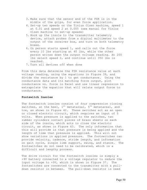
3. Make sure that the sensor end of the FSR is in the<br />
middle of the grips, for even force application.<br />
4. Set-up two speeds on the Tinius Olsen machine, speed 1<br />
at 0.01 and speed 2 at 0.005 (see manual for Tinius<br />
Olsen machine to set-up speeds)<br />
5. Hook up the insole to the transmitter telemetry<br />
device, attach probes from a digital multimeter to the<br />
output of the receiver box, and turn on both telemetry<br />
boxes.<br />
6. On person starts speed 1, and calls out the force<br />
every 10 lbs starting at 40 lbs, while the other<br />
person writes down the output voltage reading. At 200<br />
lbs select speed 2, and continue until 350 lbs is<br />
reached.<br />
7. Turn all devices off when done<br />
From this data determine the FSR resistance value at each<br />
voltage reading, using the equations in Figure 39, and<br />
divide the resistance by 1 to get conductance. Using the<br />
conductance data and its matching force output, plot<br />
conductance vs. force in Excel and use linear regression to<br />
extrapolate the equation that will relate output force to<br />
conductance.<br />
Footswitch Insoles<br />
The footswitch insoles consist of four compression closing<br />
switches, at the heel, 1 st metatarsal, 5 th metatarsal, and<br />
toe, as shown in Figure 42. These switches act as an open<br />
or closed electric circuit, which requires an input of 5<br />
volts. When pressure is applied to the switches, two<br />
rubber cylinders contact pieces of brass sheets on each<br />
side of the insole, which acts to close the electric<br />
circuit, as shown in Figure 43. The only information that<br />
this will provide is that pressure is being applied and the<br />
length of time that pressure is applied. This will not<br />
show variations in applied pressure. The footswitches can<br />
provide velocity, cadence, stride length, and information<br />
on gait cycle, single limb support, swing, and stance. The<br />
footswitches do not need to be calibrated, which is a<br />
difficult and lengthy process.<br />
The drive circuit for the footswitch insoles is simply a<br />
+9V battery connected to a voltage regulator to reduce the<br />
input voltage to +5V, which is shown in Figure 37. The<br />
footswitches are connected to the transmitter with a pulldown<br />
resistor in between. The pull-down resistor is need<br />
Page 50


