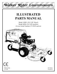
OPERATOR'S AND PARTS MANUAL - Walker Mowers
OPERATOR'S AND PARTS MANUAL - Walker Mowers
OPERATOR'S AND PARTS MANUAL - Walker Mowers

Create successful ePaper yourself
Turn your PDF publications into a flip-book with our unique Google optimized e-Paper software.
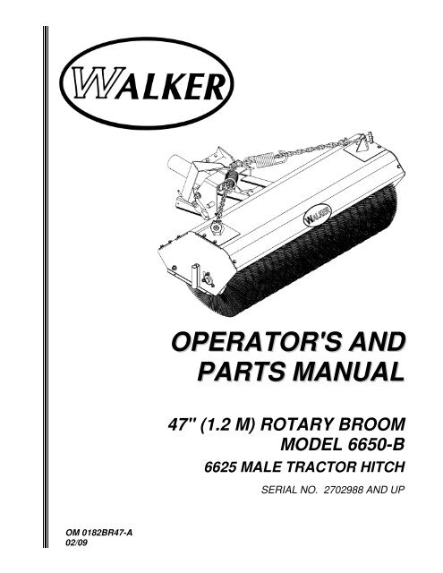
<strong>OPERATOR'S</strong> <strong>AND</strong><br />
<strong>PARTS</strong> <strong>MANUAL</strong><br />
47" (1.2 M) ROTARY BROOM<br />
MODEL 6650-B<br />
6625 MALE TRACTOR HITCH<br />
SERIAL NO. 2702988 <strong>AND</strong> UP<br />
OM 0182BR47-A<br />
02/09
Foreword<br />
Thank you...for purchasing a <strong>Walker</strong> rotary broom. Every effort has been made to provide you with<br />
the most reliable product on the market, and we are sure you will be among our many satisfied<br />
customers. It for any reason this product does not perform to you expectations, please contact us at<br />
(970) 221-5614. Every customer is important to us. Your satisfaction is our goal.<br />
Please... read this manual thoroughly! This manual is to be used in conjunction with this mower<br />
owner’s manual and the engine manufacturer’s manual for the specific engine on the mower model<br />
you are using. Before you operate your new rotary broom, please read this entire manual.<br />
Some of the information is crucial for proper operation and maintenance of this product – it will help<br />
protect your investment and ensure that the rotary broom performs to your satisfaction. Some of the<br />
information is important to your safety and must be read and understood to help prevent possible<br />
injury to your operator or others. If anything in this manual is confusing or hard to understand, please<br />
call your service department, at (970) 221-5614, for clarification before operating or servicing this<br />
product.<br />
This manual covers the Model 6650-B Rotary broom<br />
All shields and guards must be in place for the proper and safe operation of this rotary broom.<br />
Where they are shown removed in this manual, it is for illustration purposes only. Do not operate this<br />
product unless all shields and guards are in place.<br />
<strong>Walker</strong> Mfg. Co. is continually striving to improve the design and performance of its products. We<br />
reserve the right to make changes in specifications and design without thereby incurring any<br />
obligation relative to previously manufactured products.<br />
Sincerely<br />
WALKER MANUFACTURING COMPANY<br />
Bob <strong>Walker</strong>, President
TABLE OF CONTENT<br />
INTRODUCTION – TO THE PURCHASER ..........................................................................................3<br />
SAFETY PRECAUTIONS .....................................................................................................................4<br />
Before Operation..........................................................................................................................4<br />
Notice...........................................................................................................................................5<br />
Subframe & Rotary Broom ...........................................................................................................5<br />
Before Operation ...........................................................................................................5<br />
Rotary Broom & Subframe Operation ............................................................................6<br />
Maintenance ................................................................................................................................8<br />
DECALS ...............................................................................................................................................9<br />
ASSEMBLY ........................................................................................................................................10<br />
Hitch Installation – Tractor side..................................................................................................10<br />
Attaching Quick Hitch to Tractor.................................................................................10<br />
Adjustment.................................................................................................................10<br />
Wiring .......................................................................................................................11<br />
Rotary Broom Assembly ............................................................................................................12<br />
Parking Stand ..............................................................................................................12<br />
Attaching Rotary Broom to Tractor...............................................................................12<br />
Removing Rotary Broom from Tractor .........................................................................13<br />
Lawn Dethatching Wheel Kit – WAL0001 (Option).......................................................14<br />
OPERATION.......................................................................................................................................15<br />
General Preparation ..................................................................................................................15<br />
Operation ...................................................................................................................................15<br />
Rotary Brook Controls..................................................................................................15<br />
Manual Angling Adjustment .........................................................................................15<br />
Pivot Lock Pin..............................................................................................................15<br />
Ground Pressure Adjustment.......................................................................................16<br />
General Sweeping ......................................................................................................17<br />
Lawn Dethatching & Leaf Raking.................................................................................17<br />
Snow Removal ............................................................................................................17<br />
OM 0182BR47-A 1
TABLE OF CONTENT<br />
MAINTENANCE..................................................................................................................................18<br />
Maintenance ..............................................................................................................................18<br />
Hardware.....................................................................................................................18<br />
Troubleshooting .........................................................................................................................18<br />
Debris Accumulation in Front.......................................................................................18<br />
Uneven Wear of the Brush...........................................................................................18<br />
Premature Wear of the Driveline..................................................................................18<br />
Chain Replacement .....................................................................................................19<br />
Shearbolt Replacement ...............................................................................................19<br />
Brush Replacement .....................................................................................................20<br />
Lubrication .................................................................................................................................22<br />
Storage ......................................................................................................................................24<br />
<strong>PARTS</strong>................................................................................................................................................25<br />
Introduction................................................................................................................................25<br />
Male Quick Hitch Assembly – 6625............................................................................................26<br />
Male Quick Hitch System...........................................................................................................27<br />
Rotary Broom Assembly – 6650-B.............................................................................................28<br />
Pivot Bracket & Female Hitch Assembly ....................................................................................31<br />
Male Driveline - 6651.................................................................................................................32<br />
Gearbox -4500024.....................................................................................................................33<br />
Lawn Dethatching Wheel Kit – WAL0001 (Option).....................................................................34<br />
AVAILABLE OPTION..........................................................................................................................35<br />
AVAILABLE EQUIPMENT ..................................................................................................................36<br />
TORQUE SPECIFICATION TABLE....................................................................................................37<br />
OM 0182BR47-A 2
INTRODUCTION<br />
TO THE PURCHASER<br />
All products are designed to give safe,<br />
dependable service if they are operated and<br />
maintained according to instructions. Read<br />
and understand this manual before<br />
operation.<br />
This manual has been prepared to assist the<br />
owner and operators in the safe operation and<br />
suitable maintenance of the rotary broom. The<br />
information is applicable to products at the time<br />
of manufacture and does not include<br />
modifications made afterwards.<br />
Illustrations<br />
The illustrations may not necessarily reproduce<br />
the full detail and the exact shape of the parts<br />
or depict the actual models, but are intended<br />
for reference only.<br />
Direction Reference<br />
All references to right and left, forward or<br />
rearward, are from the operator's seat, facing<br />
the steering wheel.<br />
Read and understand this operator's manual<br />
before attempting to put equipment into<br />
service. Familiarize yourself with the operating<br />
instructions and all the safety<br />
recommendations contained in this manual and<br />
those labeled on the equipment and on the<br />
tractor. Follow the safety recommendations<br />
and make sure that those with whom you work<br />
follow them.<br />
To assist your dealer in handling your needs, please record hereafter the model number and serial<br />
number of your rotary broom and tractor. It is also advisable to supply them to your insurance<br />
company. It will be helpful in the event that rotary broom or tractor is lost or stolen.<br />
TRACTOR<br />
ROTARY BROOM<br />
MODEL:<br />
SERIAL NUMBER:<br />
DATE OF PURCHASE:<br />
DEALER NAME:<br />
OM 0182BR47-A 3
SAFETY PRECAUTIONS<br />
SAFETY FIRST<br />
This symbol, the industry's "Safety Alert Symbol", is used throughout this manual and on<br />
labels on the machine itself to warn of the possibility of personal injury. Read these<br />
instructions carefully. It is essential that you read the instructions and safety regulations<br />
before you attempt to assemble or use this rotary broom.<br />
DANGER :<br />
Indicates an immediate hazardous situation which, if not avoided, will<br />
result in death or serious injury.<br />
WARNING : Indicates a potentially hazardous situation which, if not avoided, could<br />
result in death or serious injury.<br />
CAUTION :<br />
Indicates a potentially hazardous situation which, if not avoided, may<br />
result in minor or moderate injury.<br />
IMPORTANT :<br />
Indicates that rotary broom or property damage could result if instructions<br />
are not followed.<br />
NOTE :<br />
Gives helpful information.<br />
All products are designed to give safe, dependable service if they are operated and maintained<br />
according to instructions. Read and understand this manual before operation. It is the owner's<br />
responsibility to be certain anyone operating this product reads this manual, and all other applicable<br />
manuals, to become familiar with this rotary broom and all safety precautions. Failure to do so could<br />
result in serious personal injury or rotary broom damage. If you have any questions, consult your<br />
dealer.<br />
BEFORE OPERATION<br />
Children<br />
Tragic accidents can occur if the operator is not<br />
alert to the presence of children. Children are<br />
generally attracted to machines and the work<br />
being done. Never assume children will remain<br />
where you last saw them.<br />
1. Keep children out of the operating area and<br />
under the watchful eye of another responsible<br />
adult.<br />
2. Be alert and turn machine off if children enter<br />
the work area.<br />
3. Before and when backing, look behind for<br />
small children.<br />
4. Never carry children while operating the<br />
machine. They may fall off and be seriously<br />
injured or interfere with the safe operation of<br />
the machine.<br />
5. Never allow children to play on the machine or<br />
rotary broom even when they are turned off.<br />
6. Never allow children to operate the machine<br />
even under adult supervision.<br />
7. Use extra care when approaching blind<br />
corners, shrubs, trees, or other obstructions<br />
that might hide children from sight.<br />
OM 0182BR47-A 4
NOTICE<br />
SAFETY PRECAUTIONS - continued<br />
A safe operator is the best assurance against accidents. All operators, no matter how experienced<br />
they may be, should read this operator's manual and all other related manuals before attempting to<br />
operate the rotary broom. Please read the following section and pay particular attention to all safety<br />
recommendations contained in this manual and those labeled on the rotary broom and on the tractor.<br />
SUBFRAME & ROTARY BROOM<br />
Before Operation<br />
1. Read and understand both the tractor and<br />
the rotary broom operator's manual before<br />
using the rotary broom. Know how to<br />
operate all controls and how to stop the<br />
unit and disengage the controls quickly.<br />
Lack of knowledge can lead to accidents.<br />
2. Never wear loose, torn, or bulky clothing<br />
around the tractor, the subframe and the<br />
rotary broom. It may catch on moving parts<br />
or controls, causing injury.<br />
3. Before and during seasons, thoroughly<br />
inspect the area where the rotary broom is<br />
to be used and remove all objects that may<br />
be thrown or cause damage to the rotary<br />
broom.<br />
4. Do not operate rotary broom in wintertime<br />
without wearing adequate winter garments.<br />
Always wear protective clothing.<br />
5. Never attempt to make any adjustments<br />
while engine is running. Read this manual<br />
carefully to acquaint yourself with the<br />
rotary broom as well as the tractor<br />
operator's manual. Working with unfamiliar<br />
rotary broom can lead to accidents. Be<br />
thoroughly familiar with the controls and<br />
proper use of the rotary broom.<br />
6. Keep all safety guards in place and verify<br />
hardware for proper tightening.<br />
7. Check for moving parts excessive wear<br />
regularly. Replace worn parts with genuine<br />
parts.<br />
8. Replace all missing, illegible, or damaged<br />
safety and warning decals. See list of<br />
decals in operator's manual.<br />
9. Do not modify or alter this rotary broom or<br />
any of its components, or any rotary broom<br />
function without first consulting your dealer.<br />
10. Keep safety decals clean of dirt and grime.<br />
11. Make sure the tractor is counterweighted<br />
as recommended by your dealer. Weights<br />
provide the necessary balance to improve<br />
stability, traction and steering.<br />
OM 0182BR47-A 5
SAFETY PRECAUTIONS - continued<br />
Rotary Broom & Subframe Operation<br />
1. Before leaving the tractor unattended, take<br />
all possible precautions. Park the<br />
tractor/rotary broom on level ground, place<br />
the transmission in neutral, set the parking<br />
brake, disengage the PTO, lower the rotary<br />
broom to the ground, place all levers<br />
including auxiliary control levers in neutral,<br />
shut off the engine and remove the ignition<br />
key.<br />
2. Before starting the tractor/ rotary broom,<br />
inspect and clean every rotating part.<br />
3. Prior to operation, clear work area of all<br />
objects that can be picked up and thrown.<br />
Mark all curbs, pipes, etc. that cannot be<br />
moved.<br />
4. Be sure the PTO switch/lever is in OFF<br />
position before starting engine.<br />
5. Exercise extreme caution when operating<br />
on or crossing a gravel drive, walks, or<br />
roads. Stay alert for hidden hazards or<br />
traffic.<br />
6. Do not carry passengers.<br />
7. Keep clear of all rotating parts. Do not put<br />
hands or feet under, or into rotary broom<br />
and subframe with engine running. Be<br />
especially observant of the rotary broom<br />
areas of discharge, intake or all other<br />
mechanical motions.<br />
8. Park the tractor/rotary broom on level<br />
ground, place the transmission in neutral,<br />
set the parking brake, disengage the PTO,<br />
lower the rotary broom to the ground, place<br />
all control levers in neutral, shut off the<br />
engine, remove the ignition key and allow<br />
the rotating parts to stop BEFORE making<br />
any repairs, adjustments or inspections.<br />
9. If the rotary broom starts to vibrate<br />
abnormally, disengage the PTO, stop the<br />
engine immediately and check for cause.<br />
Excessive vibration is generally a sign of<br />
trouble.<br />
10. Do not run the engine indoors except when<br />
starting engine and transporting attachment<br />
in or out of building. Carbon monoxide gas<br />
is colorless, odorless and deadly.<br />
11. Never operate rotary broom without<br />
guards, and other safety protective devices<br />
in place. All tractor and rotary broom<br />
shields and covers must be correctly<br />
installed at all times. When necessary to<br />
remove these, they must be reinstalled<br />
immediately.<br />
12. Never operate rotary broom near glass<br />
enclosures, automobiles, window wells,<br />
embankments, etc., without proper<br />
adjustment of snow discharge angle.<br />
13. Never operate rotary broom at high<br />
transport speeds on a slippery surface.<br />
14. Use extra caution when backing up.<br />
15. Disengage power to rotary broom when<br />
transporting or when not in use.<br />
16. Never operate the rotary broom without<br />
good visibility and lighting.<br />
17. Prolonged exposure to loud noise can<br />
cause impairment or loss of hearing. Wear<br />
a suitable hearing protective device such as<br />
earmuffs or earplugs to protect against<br />
objectionable or uncomfortable noises.<br />
18. Never allow anyone near the work area.<br />
19. Securely connect rotary broom drive shaft.<br />
Check that all tractor and rotary broom<br />
drivelines are in good working order.<br />
Rotary broom drive shaft coupler must<br />
securely lock to and be retained by annular<br />
groove on tractor drive shaft.<br />
OM 0182BR47-A 6
SAFETY PRECAUTIONS - continued<br />
20. Never allow anyone to operate the rotary<br />
broom until they have read the manual<br />
completely and are thoroughly familiar with<br />
basic tractor and rotary broom operation.<br />
21. Make sure the tractor is counterweighted<br />
as recommended by your dealer. Weights<br />
provide the necessary balance to improve<br />
stability, traction and steering.<br />
22. Always make sure all rotary broom<br />
components are properly installed and<br />
securely fastened BEFORE operation.<br />
23. Make sure nobody is in the working area of<br />
the rotary broom. The debris that can be<br />
thrown could cause serious personal<br />
injuries.<br />
24. Do not allow passengers on the<br />
tractor/rotary broom at any time. There is<br />
no safe place for passengers on this rotary<br />
broom. The operator MUST sit in the<br />
tractor seat.<br />
25. Eye and hearing protection is<br />
recommended when operating the rotary<br />
broom.<br />
26. Inspect the rotary broom after striking any<br />
foreign object to assure that all rotary<br />
broom parts are safe and secure and not<br />
damaged.<br />
27. Be especially observant of the operating<br />
area and terrain. Watch for holes, rocks, or<br />
other hidden hazards. ALWAYS inspect<br />
the area prior to operating rotary broom.<br />
28. DO NOT operate rotary broom near the<br />
edge of drop-offs or banks.<br />
29. DO NOT operate rotary broom on steep<br />
slopes as overturn may result.<br />
30. Operate up and down (not across)<br />
intermediate slopes. Avoid sudden starts<br />
and stops.<br />
31. Drive tractor backwards up steeper slopes<br />
with rotary broom off. Then operate as you<br />
travel down the slope.<br />
32. Slow down before you change directions<br />
on any slope.<br />
33. Make sure the tractor is counterweighted<br />
as recommended by your dealer. Weights<br />
provide the necessary balance to improve<br />
stability, traction and steering.<br />
34. Never stand alongside of the rotary broom<br />
while the engine is running.<br />
35. Always disengage rotary broom drive prior<br />
to transporting unit.<br />
OM 0182BR47-A 7
MAINTENANCE<br />
SAFETY PRECAUTIONS - continued<br />
ALWAYS USE GENUINE <strong>PARTS</strong> WHEN<br />
REPLACEMENT <strong>PARTS</strong> ARE REQUIRED<br />
1. Keep the tractor and rotary broom properly<br />
maintained.<br />
2. Park the tractor/rotary broom on level<br />
ground, place the transmission in neutral,<br />
set the parking brake, disengage the PTO,<br />
lower the rotary broom to the ground, place<br />
all control levers in neutral, shut off the<br />
engine and remove the ignition key and<br />
allow the rotating parts to stop BEFORE<br />
making any rotary broom adjustments.<br />
3. To avoid injury, do not adjust, unblock the<br />
driving system, or service the rotary broom<br />
with the tractor engine running. Make sure<br />
rotating components have completely<br />
stopped before leaving the operator’s seat.<br />
4. Keep the tractor/rotary broom clean. Snow<br />
, dirt or ice build-up can lead to malfunction<br />
or personal injury from thawing and<br />
refreezing in garage.<br />
5. Always wear eye protection when cleaning<br />
or servicing the rotary broom or subframe.<br />
6. DO NOT service the tractor while the<br />
engine is running or hot, or if the unit is in<br />
motion. Always lower rotary broom to the<br />
ground. If necessary to service rotary<br />
broom in raised position, securely support<br />
with stands or suitable blocking before<br />
working underneath. Do not rely on<br />
hydraulically supported devices for your<br />
safety. They can settle suddenly, leak<br />
down, or be accidentally lowered.<br />
7. Do not attempt to service machine, clear<br />
obstructions or unclog the rotary broom's<br />
driving system with the engine running.<br />
Always shut off engine and allow all motion<br />
to cease.<br />
8. The manufacturer will not claim<br />
responsibility for fitment of unapproved<br />
parts and/or accessories and any damages<br />
as a result of their use.<br />
9. Make sure all shields and guards are<br />
securely in place following all service,<br />
cleaning, or repair work.<br />
10.Do not modify or alter this rotary broom or<br />
any of its components or operating<br />
functions. If you have questions concerning<br />
modifications, consult with your dealer.<br />
11.Do not operate a rotary broom that is<br />
defective or has missing parts. Make sure<br />
that all recommended maintenance<br />
procedures are completed before operating<br />
the rotary broom.<br />
12.Check all controls regularly and adjust<br />
where necessary. Make sure that the<br />
brakes are evenly adjusted.<br />
13.Periodically check all nuts and bolts for<br />
tightness, especially wheel hub and rim<br />
nuts.<br />
14.To avoid serious personal injury: Escaping<br />
hydraulic/diesel fluid under pressure can<br />
penetrate the skin causing serious injury.<br />
Do not use your hands to check for leaks.<br />
Use a piece of cardboard or paper to<br />
search for leaks.<br />
15.Stop engine and relieve pressure before<br />
connecting or disconnecting hydraulic<br />
hoses. Tighten all connections before<br />
starting engine or pressurizing hoses.<br />
OM 0182BR47-A 8
DECALS<br />
Replace immediately if damaged<br />
661051<br />
2500584<br />
660328<br />
660988<br />
2500515<br />
658708<br />
9
ASSEMBLY<br />
HITCH INSTALLATION – TRACTOR SIDE<br />
Before installing this hitch make sure engine is off and parking brake is set.<br />
Attaching Quick Hitch to Tractor<br />
1. Lightly grease the deck support arm shaft<br />
(fig.1, item 1) on the tractor.<br />
2. Engage adaptor frame tube sockets (fig.1,<br />
item 2) onto the tractor support arms (fig.1,<br />
item 1) and slide on as shown in figure 2.<br />
Continue to slide on until you can install a<br />
hitch pin (fig.3, item 1) through the hole in<br />
each end of the support arm shafts.<br />
IMPORTANT: If tractor body needs to be<br />
raised, the PTO shield must be in closed or<br />
down position and the equipment must be<br />
in the lowered position. The only time the<br />
PTO shield needs to be open or raised is<br />
when connecting or disconnecting the<br />
driveline for the snowblower or the rotary<br />
broom.<br />
Adjustment<br />
Loosen the 3/4” jam nut (fig.4, item 1) or (fig.1,<br />
item 3). Adjust the 3/4” hexagon bolt (fig.4,<br />
item 2) until it contacts the cross-member of<br />
the tractor frame, and securely tighten the 3/4”<br />
nut to prevent the bolt from moving.<br />
IMPORTANT: This adjustment is<br />
needed only once if the same tractor and<br />
adaptor are used together. If you plan to mix<br />
tractors and adaptors, this adjustment will be<br />
required each time you mount an equipment<br />
adaptor. Wiring<br />
1<br />
Figure 2<br />
1<br />
Figure 3<br />
2<br />
1<br />
3<br />
2<br />
1 2<br />
Figure 1<br />
Figure 4<br />
OM 0182BR47-A 10
3. Figure 5: Drill five 13/64” (5 mm) dia. holes<br />
in the tractor: two in the forward speed<br />
control arm and three in the body as.<br />
4. Figure 6: Attach the toggle switch<br />
mounting bracket (item 1) on the forward<br />
speed control arm using two 10—24 x 1/2”<br />
bolts and kept nut. At this time, you need to<br />
connect the green ground wire from the<br />
wiring harness to a bolt of the switch<br />
mounting bracket.<br />
5. Figure 6: Install the wiring<br />
harness to the tractor body as<br />
shown using three wiring clamps<br />
(item 2), three 10— 24 x 3/8” bolts<br />
and kept nuts.<br />
6. Attach the toggle switch to the<br />
mounting bracket, placing the<br />
switch terminals toward the front<br />
of the tractor.<br />
ASSEMBLY<br />
1<br />
7. Connect the harness red wire to the free<br />
connector of the PTO clutch switch red<br />
wire.<br />
8. Complete the wiring by connecting the<br />
wiring harness to the toggle switch and to<br />
the actuator motor.<br />
9. Figure 7: Check wiring diagram and<br />
correct if necessary.<br />
2<br />
2<br />
2<br />
Figure 6<br />
Figure 5<br />
Figure 7<br />
OM 0182BR47-A 11
ROTARY BROOM ASSEMBLY<br />
ASSEMBLY<br />
The rotary broom is assembled at the factory, however, parts contained in the bag must be installed.<br />
Use the present manual and lay out all parts for assembly. Separate bolts and nuts into various sizes.<br />
After assembly, torque all the bolts according to the Torque Specification Table enclosed at the end of<br />
the manual.<br />
Parking Stand<br />
(Figure 8)<br />
1. Lift the broom until you can insert a parking<br />
stand (item 1) into each holder from the<br />
underside.<br />
2. Install a 5/32" x 1 1/4" cotter pin (item 2) in<br />
the upper hole of each parking stand.<br />
3. Set the parking stands in the position<br />
where they touch the ground and secure<br />
with 1/4" x 2" round wire lock pins (item 3).<br />
Figure 8<br />
Attaching Rotary Broom to Tractor<br />
(Figures 9-10)<br />
IMPORTANT: Make sure the pivot lock pin<br />
(fig 10, item A) is in the innermost position<br />
to prevent female hitch from bouncing and<br />
to facilitate hitching<br />
1. Support the broom female hitch (item 1) on<br />
a 2 1/2" (60 mm) thick piece of wood.<br />
2. Move quick hitch lever (item 8) rearward to<br />
unlock position.<br />
3. Connect the male driveline (item 2)<br />
supplied with the drive kit to broom female<br />
driveline (item 3) and support with the<br />
driveline support (item 5).<br />
4. Lower the nose of the male quick hitch as<br />
much as possible.<br />
5. Introduce the male quick hitch (item 4) in<br />
the broom female hitch (item 1) and move<br />
the engagement lever (item 8) forward to<br />
locked position. Secure latch (item 7) with<br />
linch pin (item 6).<br />
6. Connect male driveline (item 2) to subframe<br />
drive shaft by sliding back locking collar on<br />
driveline yoke and pushing yoke over shaft<br />
until locking collar snaps back and push<br />
driveline support down (item 5).<br />
WARNING:<br />
To avoid serious personal injuries:<br />
Before getting off the tractor: Park the<br />
tractor on level ground, place the<br />
transmission in neutral, set the<br />
parking brake, disengage the driving<br />
system, lower the nose of the male<br />
quick hitch as much as possible, place<br />
all levers including auxiliary control<br />
levers in neutral, shut off the engine<br />
and remove the ignition key.<br />
Figure 9<br />
OM 0182BR47-A 12
ASSEMBLY<br />
7. Put the pivot lock pin (fig. 10, item A) in the<br />
outermost position and secure with the<br />
hairpin.<br />
Figure 10<br />
WARNING:<br />
To avoid serious personal injuries: This<br />
shaft turns at up to 2000 RPM. If the collar<br />
is not locked to the shaft at tractor end, or if<br />
the yoke at the broom end is not secured<br />
properly (a "click" must be heard), the<br />
driveline can fly loose with great force<br />
capable of causing serious injury or death.<br />
Removing Rotary Broom from Tractor<br />
Set and secure the parking stands in the<br />
position where they touch the ground, lower the<br />
rotary broom on a flat and level surface, put<br />
pivot lock pin (fig. 10, item A) in the innermost<br />
position then reverse the installation procedure.<br />
OM 0182BR47-A 13
ASSEMBLY<br />
LAWN DETHATCHING WHEEL KIT - WAL0001 (OPTION)<br />
Installation<br />
(Figure 11)<br />
1. Remove the parking stands (item 9) from<br />
the supports (item 1) on each side of the<br />
broom. Remove the chain guard (item 11)<br />
by unscrewing the two bolts (item 10) to<br />
gain access to the inferior hole on the left<br />
side of the broom.<br />
2. Remove the lower 5/16" x 1/2" flange bolt<br />
(item 7) from the support. Loosen the upper<br />
5/16" x 1/2" flange bolt and then turn<br />
support counter clockwise to remove it.<br />
3. Attach the left wheel assembly on the<br />
broom left side as shown on figure with two<br />
5/16"NC x 1" serrated flange bolts (item 5),<br />
5/16"NC serrated flange nuts (item 6) and a<br />
5/16"NC x 1/2" serrated flange bolt (item 7).<br />
4. Attach the right wheel assembly on the<br />
broom right side with the two existing bolts<br />
(item 8), and as for the left side, with a<br />
5/16"NC x 1/2" serrated flange bolt (item 7).<br />
5. Insert the assembled wheel<br />
adjustments (item 3) into the<br />
left and right wheel supports<br />
(item 2) and secure in place to<br />
the maximum height with a<br />
round wire lock pin (item 4).<br />
6. Reinstall the parking stands<br />
(item 9) to the working<br />
position in the wheel supports<br />
as well as the chain guard<br />
(item 11).<br />
Figure 11<br />
Adjustment<br />
To adjust the height of the wheel -1/2" (13 mm)<br />
at a time, from 3" (76 mm) minimum to 7" (178<br />
mm) maximum - slide the inner tube upward or<br />
downward, as needed, and insert the round<br />
wire lock pin in the open hole.<br />
We recommend adjusting the wheel height to<br />
1" (25 mm) lower than the brush height to<br />
make a first try on the grass. Then raise or<br />
lower the wheels as required.<br />
(76 mm) (178 mm)<br />
OM 0182BR47-A 14
OPERATION<br />
GENERAL PREPARATION<br />
1. Check drive shaft tightening.<br />
2. Make sure that the broom operates freely.<br />
3. Adjust the lawn dethatching wheels (if<br />
installed).<br />
4. Secure the parking stands in the position<br />
where they do not touch the ground (up).<br />
WARNING: To avoid serious<br />
injuries:<br />
• Do not allow bystanders near working<br />
area.<br />
• Do not allow anyone to ride on rotary<br />
broom or quick hitch.<br />
• Before cleaning, adjusting or repairing<br />
the rotary broom : bring the tractor to a<br />
complete stop, wait for all movement to<br />
stop, apply parking brake, lower the<br />
implement to the ground, shut off the<br />
engine and remove the ignition key.<br />
• Never put any part of your body under<br />
the rotary broom while making<br />
adjustments.<br />
ATTENTION<br />
Always operate the broom from the<br />
operator's seat only. Never allow anyone to<br />
ride on the machine.<br />
ATTENTION<br />
Operate the broom at a speed that matches<br />
the working conditions. Be extremely<br />
careful when working on banks or uneven<br />
terrain.<br />
ATTENTION<br />
Always wear protective eyewear when<br />
operating the broom.<br />
OPERATION<br />
Rotary Broom Controls<br />
1. Use the tractor PTO to start and stop the<br />
brush. Start the engine and put the throttle<br />
lever at 1/3 speed. Engage the PTO. To<br />
stop, disengage the PTO.<br />
2. Raise and lower the broom using the<br />
hydraulic lift lever located on the left wing of<br />
the tractor. Pulling the lever backward<br />
raises the broom, pushing the lever forward<br />
lowers the broom and pushing the lever<br />
fully forward sets the broom in floating<br />
action.<br />
3. Control brush speed with the throttle.<br />
Under most conditions, if the brush speed<br />
is too fast, it results in debris coming over<br />
the hood onto the operator.<br />
Manual Angling Adjustment<br />
(Figure 12)<br />
1. This rotary broom is able to swivel to five<br />
positions: straight, two left and two right<br />
(12.5° and 25°).<br />
2. To adjust, raise the rotary broom off the<br />
ground, carefully lift the adjustment lever<br />
(item 1), select the desired angle position<br />
then release the lever. Make sure the<br />
rotary broom is locked in position at the<br />
desired angle.<br />
Pivot Lock Pin<br />
(Figure 12)<br />
The innermost position of the pivot lock pin<br />
(item 3) is used to prevent the female hitch<br />
from being pulled up by the action of the<br />
spring, to facilitate installation and removal<br />
of rotary broom. Do not work with the pivot<br />
lock pin in the innermost position or<br />
damage to the broom could occur.<br />
OM 0182BR47-A 15
Ground Pressure Adjustment<br />
(Figure 12)<br />
This adjustment must be made when the<br />
broom is attached to the tractor.<br />
IMPORTANT: The pivot lock pin (item 3)<br />
MUST BE in the outermost position.<br />
10. For the most efficient sweeping, the brush<br />
must have good ground contact without too<br />
much pressure being placed on the bristles<br />
in order to prevent them from bending<br />
which would result in premature wear of the<br />
brush.<br />
11. Check to make sure the tractor's tire<br />
pressure is right.<br />
12. Find a hard and dirty surface. Lower the<br />
brush to the ground, engage the broom and<br />
let the brush turn for 15 to 30 seconds while<br />
remaining in place. Disengage the broom<br />
with raising it and wait for the brush to stop<br />
turning.<br />
13. Raise the broom and back away. Once<br />
immobilized, turn the engine off.<br />
14. Measure the path cleaned. If the brush is<br />
adjusted properly, the path is between<br />
3 1/4" and 3 3/4" wide (83 and 95mm) and<br />
both sides of the path are parallel.<br />
OPERATION<br />
15. If not, adjust the spring tension with the<br />
adjustment knobs (item 2) until you obtain<br />
ground contact between 3 1/4" and 3 3/4"<br />
wide (83 and 95 mm) (fig. 5a). Turn the<br />
knobs clockwise to reduce ground pressure<br />
and counter clockwise to increase ground<br />
pressure. Make sure the weight is evenly<br />
distributed on both sides. An asymmetric<br />
adjustment may be necessary to<br />
counterbalance the weight of the broom<br />
and the ground pressure.<br />
NOTE: Further adjustment will be necessary<br />
to compensate for brush wear.<br />
NOTE: The two side bolts on top of the<br />
female hitch (Fig. 12, item 4) must not be<br />
tightened to allow the rotary broom to<br />
follow ground contours with ease.<br />
Figure 12a<br />
Figure 12<br />
(83 mm @ 95 mm)<br />
OM 0182BR47-A 16
General Sweeping<br />
OPERATION<br />
Snow Removal<br />
IMPORTANT: Always use the float position<br />
when working with the broom.<br />
1. Minimize dust by reducing brush speed<br />
and by sweeping on days with high<br />
moisture.<br />
2. For light material, angle broom 12.5° right<br />
or left rather than fully angled to obtain a<br />
wider sweeping path.<br />
3. For heavier material, reduce ground speed<br />
and angle the brush fully to the left or right<br />
to expel the accumulated debris from the<br />
sweeping path as quickly as possible thus<br />
preventing build up.<br />
4. Prevent damage to the broom by removing<br />
large foreign objects.<br />
Lawn Dethatching & Leaf Raking<br />
IMPORTANT: Optional lawn dethatching<br />
wheels must be installed to perform these<br />
tasks in order to avoid excessive ground<br />
contact.<br />
1. Bristles should barely touch the ground for<br />
lawn dethatching and leaf raking<br />
operations. (see adjustment in the section<br />
"Lawn Dethatching Wheel Kit")<br />
2. Slower brush speed and ground speed are<br />
more adequate for lawn dethatching. This<br />
will avoid bouncing which could damage<br />
the lawn due to excessive ground contact.<br />
3. Minimize dust by reducing brush speed<br />
and by sweeping when moisture is high<br />
(but not wet) whenever possible.<br />
WARNING:<br />
To avoid serious injuries: Foreign objects<br />
in snow may be thrown farther than the<br />
snow. Use the slowest brush speed that<br />
will perform the job. Stay aware of broom<br />
discharge direction.<br />
WARNING:<br />
To avoid serious injuries: Snow or ice<br />
build-up on the sweeper hood can cause a<br />
loss of tractor steering control. Regularly<br />
remove any snow or ice from the sweeper<br />
hood to prevent the excess weight from<br />
affecting steering.<br />
1. This broom's optimum performance is<br />
achieved when snow depth is 3" (76 mm)<br />
or less.<br />
2. To avoid the snow from being blown back<br />
on the tractor and operator, sweep with the<br />
wind blowing in the direction of broom<br />
discharge.<br />
3. Vary the brush speed and broom angle so<br />
the brush throws material on each side to<br />
prevent excessive accumulations.<br />
4. Brush speed must be at its maximum to<br />
obtain a better performance in wet, heavy<br />
snow or slush<br />
OM 0182BR47-A 17
MAINTENANCE<br />
MAINTENANCE<br />
ALWAYS USE GENUINE <strong>PARTS</strong> WHEN<br />
REPLACEMENT <strong>PARTS</strong> ARE REQUIRED.<br />
1. Avoid exposing broom bristles to direct<br />
sunlight for long periods to avoid damage.<br />
2. Because of the dust raised during<br />
sweeping, the tractor air cleaner should be<br />
checked daily and replaced when<br />
necessary.<br />
Hardware<br />
Check and tighten all hardware, including<br />
factory-installed hardware, before operating<br />
the rotary broom and every 8 hours of<br />
operation.<br />
TROUBLESHOOTING<br />
Debris Accumulation in Front<br />
• Reduce the travel speed.<br />
• Increase the engine rpm.<br />
• Make more than one pass.<br />
• Raise the brush to decrease the contact<br />
area.<br />
• Increase the broom angle.<br />
Uneven Wear of the Brush<br />
• Make sure there is no debris wrapped<br />
around the brush.<br />
• Check the ground pressure adjustment<br />
(see page 16)<br />
• Remove the accumulated debris under the<br />
hood.<br />
Premature Wear of the Driveline<br />
• Reduce travel speed.<br />
• Make more than one pass especially in<br />
deep, heavy debris.<br />
• Avoid ramming piles.<br />
• Lack of lubrication – lubricate more often.<br />
OM 0182BR47-A 18
MAINTENANCE<br />
Chain Replacement<br />
(Figure 13 & 13a)<br />
Replace the chain when the distance<br />
between the spans is reduced to 1 3/4"<br />
(45 mm) (see figure 13 a)<br />
1. Remove the broom from the tractor.<br />
2. Flip the broom over on some cardboard to<br />
protect the paint.<br />
3. Remove the chain guard (item 1) by<br />
removing the two bolts (item 2).<br />
4. Slide a long screwdriver (item 4) under the<br />
tensioner (item 3) to remove the tension<br />
from the chain (item 5).<br />
5. Remove the connecting link from the chain<br />
and remove the chain.<br />
6. Install the new chain making sure to<br />
position the connecting link's lock opening<br />
as shown on figure 7a.<br />
7. Reinstall the chain idler making sure to<br />
align it properly.<br />
8. Put the chain guard back in place.<br />
Shearbolt Replacement<br />
(Figure 14)<br />
1. Remove the broken shearbolt (item 1) by<br />
aligning the hole of the driveline yoke with<br />
the hole of the gearbox shaft.<br />
2. Use a drift punch to dislodge the broken<br />
bolt and replace with a 1/4"NC x 2 1/2" lg<br />
GR. 5 and 1/4" NC nylon insert locknut.<br />
Figure 14<br />
Figure 13a<br />
(45 mm)<br />
Figure 13<br />
OM 0182BR47-A 19
MAINTENANCE<br />
Brush Replacement (Figures 15 & 15a)<br />
When the brushes reach a diameter of 10"<br />
(254 mm), it is necessary to replace them in<br />
order to maximize the performance of your<br />
broom.<br />
1. Place the tractor/equipment on level<br />
ground, place transmission in neutral, wait<br />
for all movement to stop and apply parking<br />
brake.<br />
2. Raise the broom to its maximum and turn it<br />
completely to the left. Securely support<br />
with stands or suitable blocking. Do not rely<br />
on hydraulically supported devices for your<br />
safety. They can settle suddenly, leak down,<br />
or be accidentally lowered. Shut off the<br />
engine and remove the ignition key.<br />
3. Fig.15: Remove the two bolts (item 2) and<br />
withdraw the chain guard (item 1).<br />
4. Fig.15: Remove the right side of the broom<br />
(item 5) by unscrewing the three nuts<br />
(item 4), the nine bolts (item 3), the<br />
lockwasher and the nut (item 6).<br />
5. Fig.15: Remove the bearing and the<br />
flanges (item 13) by unscrewing the two<br />
setscrews from the bearing.<br />
6. Fig.15: Remove the retaining plate (item 7)<br />
by unscrewing the three bolts (item 8).<br />
7. Fig.15: Remove the brushes by sliding<br />
them towards the outside of the brush<br />
support (item 11).<br />
8. Begin installing the wafers on the brush<br />
support, ensuring the drive pins of each<br />
wafer section lock the wafer over one of<br />
the brush support’s drive bar.<br />
9. Fig.15: Insert the first brush on the brush<br />
support by aligning the guides (item 10) on<br />
each side of a brush support tube<br />
(item 11). Continue the same procedure<br />
with the remaining brushes by turning each<br />
brush 120° (12 o’clock, 4 o’clock and 8<br />
o’clock) so the guides are distributed<br />
evenly on each brush support tube.<br />
IMPORTANT: If you decide to install half<br />
steel / half polypropylene brushes, you<br />
must start and finish with a polypropylene<br />
brush.<br />
IMPORTANT: The guides (item 10) of the<br />
first brush must point toward the inside to<br />
prevent interference.<br />
Figure 15<br />
OM 0182BR47-A 20
MAINTENANCE<br />
10. SNUG FIT : To ensure a correct fit of the<br />
wafer assembly on the brush support,<br />
make sure to respect the following:<br />
• Fig.15a: The distance A from the last<br />
wafer to the end of the brush support is<br />
approximately 1/4".<br />
• Each wafer must present a small radial<br />
play after the retaining plate is<br />
reinstalled on the brush support<br />
11. QUANTITY OF WAFERS : Since wafer<br />
width can vary from 1 7/8" and 2 1/8", the<br />
quantity of wafers to install on the brush<br />
may vary from one installation to another.<br />
It is possible that some wafers included in<br />
the new wafer set will be left unused once<br />
the installation is complete.<br />
Fig.15a: If the distance A between the<br />
brush support end and the last wafer is<br />
more than 1/4", remove the last wafer,<br />
measure A and use procedure described<br />
in the following cases by rotating each<br />
wafer 120 degrees (12 o’clock, 4 o’clock<br />
and 8 o’clock) in each case:<br />
• Measure A = 3/8" to 1/2"<br />
Turn the last wafer in the same direction<br />
as the one preceding it and add 2 more<br />
wafers in the same direction. The result is<br />
four wafers in the same direction at the<br />
end of the brush.<br />
• Measure A = 5/8" to 1 1/8"<br />
Add 1 wafer in the same direction as the<br />
last one. The result is two wafers in the<br />
same direction at the end of the brush.<br />
• Measure A = 1 1/4" to 1 3/8"<br />
Turn the last wafer in the same direction<br />
as the one preceding it and add 3 more<br />
wafers in the same direction. The result is<br />
five wafers in the same direction at the<br />
end of the brush.<br />
• Measure A = 1 1/2" to 1 5/8"<br />
Add 2 wafers in the same direction as the<br />
last one. The result is three wafers in the<br />
same direction at the end of the brush.<br />
Figure 15a<br />
A<br />
A = 3/8" to 1/2" A = 5/8" to 1 1/8"<br />
A = 1 1/4" to 1 3/8" A = 1 1/2" to 1 5/8"<br />
12. Fig.15: Replace the retaining plate (item 7) by<br />
tightening the bolts (item 8) and lockwashers<br />
firmly.<br />
13. Fig.15: Install the bearing and the flanges<br />
(item 13) on the right side (item 5) and reinstall<br />
the right side of the broom. Tighten the bearing<br />
setscrews (item 13).<br />
14. Fig.15: Check the condition of the chain and<br />
realign the chain tensioner (item 12).<br />
15. Fig.15: Reinstall the chain guard (item 1).<br />
IMPORTANT: While installing the new brush,<br />
take care to tighten the bearing setscrews and<br />
to align the chain tensioner.<br />
OM 0182BR47-A 21
LUBRICATION<br />
Use a grease gun, grease and lubricate as follows:<br />
MAINTENANCE<br />
DESCRIPTION TIME INTERVAL LUBRICATION REQUIRED<br />
Driveline<br />
Drive Chain<br />
8 hours of operation<br />
20 hours of operation<br />
8 hours of operation<br />
Grease each universal joint<br />
(see decal #658708)<br />
Separate the sliding parts and cover each one<br />
of them with grease<br />
(see decal #658708)<br />
Lubricate with chain lubricant<br />
(Remove chain guard item 1)<br />
All pivot points 8 hours of operation Use a good quality multipurpose lubricant<br />
Gearbox<br />
Check oil level. If needed, add AGMA 5EP<br />
40 hours of operation extreme pressure oil, SAE 80W90 gear oil or<br />
equivalent<br />
100 hours of operation Replace oil.<br />
Bearing 8 hours of operation Grease each bearing<br />
658708<br />
OM 0182BR47-A 22
Lawn Dethatching Wheel Kit<br />
Use a grease gun, grease and lubricate as follows:<br />
MAINTENANCE<br />
DESCRIPTION TIME INTERVAL LUBRICATION REQUIRED<br />
Wheel bracket 8 hours of operation Use a good quality multipurpose lubricant<br />
Wheel support 8 hours of operation Use a good quality multipurpose lubricant<br />
Wheel 8 hours of operation Use a good quality multipurpose lubricant<br />
Male Quick Hitch<br />
Lubricate pivot shaft (item 1) and deck<br />
support arms (item 2) by the grease<br />
fittings every 50 hours of operation or<br />
monthly.<br />
1<br />
2<br />
OM 0182BR47-A 23
STORAGE<br />
Before storing the rotary broom, certain<br />
precautions should be taken to protect it from<br />
deterioration.<br />
1. Clean the rotary broom thoroughly.<br />
2. Make all the necessary repairs.<br />
3. Repaint all parts from which paint has worn<br />
or peeled.<br />
4. Lubricate the rotary broom as instructed<br />
under Lubrication.<br />
5. Replace all decals that are damaged, lost,<br />
or otherwise become illegible. If a part to<br />
be replaced has a sign on it, obtain a new<br />
decal from your dealer and install it in the<br />
same place as on the removed part.<br />
6. When the rotary broom is dry, oil all<br />
moving parts. Apply oil liberally to all<br />
surfaces to protect against rust.<br />
IMPORTANT: Do not allow oil or grease<br />
on broom bristles.<br />
7. Store broom on parking stands so that the<br />
bristles do not touch the ground.<br />
8. Store in a dry place.<br />
IMPORTANT: If broom bristles are<br />
exposed to direct sunlight, protect bristles<br />
with a tarp.<br />
MAINTENANCE<br />
OM 0182BR47-A 24
<strong>PARTS</strong><br />
INTRODUCTION<br />
All parts are illustrated in "exploded views" which show the individual parts in their normal relationship<br />
to each other. Reference numbers are used in the illustrations. These numbers correspond to those in<br />
the "Reference Number" (REF) column, and are followed by the description and quantity required.<br />
O/L - "Obtain Locally" in the part number column indicates common hardware that is available at your<br />
local hardware supply.<br />
All reference to right and left, forward or rearward from the operator's view standing behind the<br />
machine.<br />
Orders must give the complete description, correct part number, the total amount required, the serial<br />
number, the method of shipment and the shipping address.<br />
The manufacturer reserves the rights to change, modify, or eliminate from time to time, for technical or<br />
other reasons, certain or all data, specifications, or the product or products themselves, without any<br />
liability or obligation.<br />
The parts listed here are available through your local dealer.<br />
OM 0182BR47-A 25
<strong>PARTS</strong><br />
MALE QUICK HITCH ASSEMBLY - 6625<br />
REF. DESCRIPTION QTY PART NUMBER<br />
1 Male quick hitch 1 660980<br />
2 Quick hitch latch 1 657382<br />
3 Hex. bolt 3/8” NC x 1 1/2” 1 O/L<br />
4 Nylon lock nut 3/8” NC 1 O/L<br />
5 Pin 1/4” dia x 1 11/16” 1 657384<br />
6 Cotter pin 3/32" dia. x 3/4" 1 O/L<br />
7 Spring plate 1 657383<br />
8 Spring 1 657385<br />
9 Attaching lever 1 657381<br />
10 Plastic handle 1 656797<br />
11 Cotter pin 1/8” dia x 1” 2 O/L<br />
12 Flat washer 9/16” dia. hole 1 O/L<br />
13 Safety chain ass'y 1 657632<br />
OM 0182BR47-A 26
<strong>PARTS</strong><br />
MALE QUICK HITCH SYSTEM<br />
REF. DESCRIPTION QTY PART NUMBER<br />
1 Adaptor 1 6620-27<br />
2 Grease fitting 45°. 2 5830-3<br />
3 Hex. bolt 3/4” 1 F212<br />
4 Jam nut 3/4” 1 F213<br />
5 Clevis pin 2 6621-1<br />
6 Actuator motor 1 6621<br />
7 Pivot shaft 1 6620-17<br />
8 Hitch 1 6620-24<br />
9 Keps nut 10-24 1 F002<br />
10 Keps nut 1/4-20 2 F005<br />
11 Bolt 1/4-20 x 1/2" 2 F036<br />
12 Decal 1 6620-29<br />
13 PTO shield 1 6620-28<br />
14 Bushing 1 5588<br />
15 Actuator pivot 1 6620-16<br />
16 Grease fitting 1 5830<br />
17 Bolt 10-24 x 5/8" 1 F027<br />
18 Cotter pin 4 F068<br />
- Wiring harness (not illustrated) 1 6622<br />
- Toggle switch (not illustrated) 1 6623<br />
- Actuator boot (not illustrated) 1 6623-1<br />
- Bolt 10-24 x 3/8" (not illustrated) 3 F025<br />
- Bolt 10-24 x 1/2" (not illustrated) 2 F026<br />
- Harness clamp (not illustrated) 3 5832<br />
11<br />
OM 0182BR47-A 27
<strong>PARTS</strong><br />
ROTARY BROOM ASSEMBLY – 6650-B<br />
OM 0182BR47-A 28
<strong>PARTS</strong><br />
ROTARY BROOM ASSEMBLY – 6650-B<br />
REF. DESCRIPTION QTY. PART #<br />
1 Housing 1 -------<br />
2 Right side plate 1 667841<br />
3 Brush support 1 666640<br />
4 Retaining plate, brush 1 665650<br />
5 Chain guard 1 666845<br />
6 Round wire lock pin 1/4" x 2", PTD 2 1900006<br />
7 Cotter pin 1/8" x 1 3/4", PTD 1 O/L<br />
8 Cotter pin 5/32" x 1 1/4", PTD 2 O/L<br />
9 Key 1/4" x 1/4" x 1 1/4" lg 1 654643<br />
10 Pin 1/2" x 2 9/16" lg, PTD 1 658961<br />
11 Setscrew 3/8" NC x 1/2"<br />
12 Wear tube 2 666844<br />
13 Parking stand support bracket 2 659784<br />
14 Parking stand 2 666907<br />
15 Plastic handle 1 656797<br />
16 Chain 25 1/2" lg., PTD 2 666881<br />
17 Gearbox 1 4500024<br />
18 Hair pin 3mm x 65mm lg., PTD 3 1800004<br />
19 Set screw 5/16" NC x 1/4" 2 O/L<br />
20 Drive shaft 1 666631<br />
21 Key 1/4" X 1/4" X 1 1/4" 1 654643<br />
22 Key 1/4" X 1/4" X 1" 1 655379<br />
23 Sprocket 40B36 1 657405<br />
24 Chain #40 (inc. connecting link) 1 3300011<br />
25 Connecting link #40 1 656153<br />
26 Flat washer 3/8" dia. hole, PTD 3 O/L<br />
27 Wheel 4" x 2" wide 2 657991<br />
28 Flange, 3 holes with grease fitting 3 4300031<br />
29 Bearing, 1" dia. with locking screw, greasable 3 4300038<br />
30 Flange, 3 holes with groove 3 4300030<br />
31 Torsion spring 1 3800016<br />
32 Chain tensioner 1 665960<br />
33 Flat washer 9/16" dia. hole, PTD 2 O/L<br />
34 Tension spring 2 660220<br />
35 Shackle 1/4" x 7/16" pin, PTD 4 A-10368<br />
36 Circle cotter 1" x 1/16", PTD 4 1900009<br />
37 Eye bolt 5/16" NC x 6" with nut, PTD 2 663074<br />
38 Knob 5/16" NC 2 657309<br />
39 Brush set - 100% polypropylene 18" 1 BR0001<br />
Brush set - 50% polypropylene 50% steel 18" 1 BR0002<br />
Brush set - 100% steel 18" 1 BR0003<br />
Wafer brush - 100% polypropylene 18" 24 3800054<br />
Wafer brush – 100% steel; 18" 24 3800056<br />
OM 0182BR47-A 29
<strong>PARTS</strong><br />
ROTARY BROOM ASSEMBLY – 6650-B<br />
REF. DESCRIPTION QTY. PART #<br />
40 Nylon insert lock nut 1/4" NC, PTD 1 O/L<br />
41 Hex. bolt 1/2" NC x 1 3/4" lg., gr. 5, PTD 2 O/L<br />
42 Ball bearing 4 655537<br />
43 Pivot bushing 2 658532<br />
44 Flange nut 5/16" NC, PTD 9 0900036<br />
45 Flat washer 9/16" dia. hole, PTD 1 O/L<br />
46 Hex. bolt 5/16" NC X 1 1/4" lg., gr. 5, PTD 3 O/L<br />
47 Hex. bolt 3/8" NC X 5" lg., gr. 5, PTD 4 O/L<br />
48 Lockwasher 3/8", PTD 4 O/L<br />
49 Carriage bolt 5/16" x 3/4" lg., gr. 5, PTD 9 0300002<br />
50 Serrated flange bolt 5/16" x 1/2" lg., gr. 2, PTD 11 0200065<br />
51 Serrated flange bolt 5/16" x 1" lg., gr. 2, PTD 2 0200091<br />
52 Hex. bolt 1/4" NC x 2 1/2" lg., gr.5, PTD 1 O/L<br />
53 Lockwasher 5/16", PTD 3 O/L<br />
54 Nylon insert lock nut 1/2" NC, PTD 2 O/L<br />
55 Hex. nut 3/8" NC, PTD 4 O/L<br />
56 Wheel bushing 4 658536<br />
57 Wheel cup 4 658531<br />
58 Nylon insert lock nut 5/16" NC, PTD 1 O/L<br />
OM 0182BR47-A 30
<strong>PARTS</strong><br />
PIVOT BRACKET & FEMALE HITCH ASSEMBLY<br />
REF. DESCRIPTION QTY. PART #<br />
1 Broom pivot 1 667605<br />
2 Female hitch 1 667129<br />
3 Upper coupler 1 661009<br />
4 Upper bushing 1 658528<br />
5 Angling plate 1 659641<br />
6 Handle 1 663640<br />
7 Driveline support 1 666979<br />
8 Wheel bracket - LH 1 658534<br />
9 Wheel bracket - RH 1 658533<br />
10 Grease fitting 1/4" NF 2 654106<br />
11 Nylon ring 0.630" hole 4 658578<br />
12 Tension spring Ø9/16" x 1 1/2" 1 657989<br />
13 Hex. bolt 7/16" NC x 1 3/4" lg. Gr. 5, PTD 1 O/L<br />
14 Hex. bolt 7/16" NC x 1 1/4" lg. Gr. 5, PTD 1 O/L<br />
15 Hex. bolt 5/16" NC x 1" lg. Gr. 5, PTD 2 O/L<br />
16 Stover nut 5/8" NC PTD 1 1100007<br />
17 Nylon insert lock nut 7/16" NC, PTD 1 O/L<br />
18 Hex. nut 7/16" NC, PTD 1 O/L<br />
19 Nylon insert lock nut 5/16" NC, PTD 2 O/L<br />
20 Lockwasher 7/16", PTD 1 O/L<br />
21 Flat washer 1/2" hole, PTD 1 O/L<br />
22 Flat washer 3/8" hole, PTD 2 O/L<br />
23 Cotter pin 3/16 x 1 1/2" lg, PTD 2 O/L<br />
24 Cotter pin 3/32 x 3/4" lg, PTD 2 O/L<br />
25 Spring pin 3/16" x 1" lg, PTD 1 O/L<br />
OM 0182BR47-A 31
<strong>PARTS</strong><br />
DRIVELINE ASSEMBLY MALE PORTION 6651<br />
REF. DESCRIPTION QTY. PART #<br />
1 Outer shield 1 6651-1<br />
2 Nylon bearing 1 6651-2<br />
3 Bearing retainer 1 6651-3<br />
4 Male shaft and yoke assembly 1 6651-4<br />
OM 0182BR47-A 32
GEAR BOX - 4500024<br />
<strong>PARTS</strong><br />
REF. DESCRIPTION QTY. PART #<br />
1 Casing 1 664659<br />
2 Bolt M8 x 45 8 0200098<br />
3 Hex. nut M8 8 0900029<br />
4 Plug 3/8" 1 661739<br />
5 O-ring 1 664656<br />
6 Oil seal 2 661730<br />
7 Bearing 2 661728<br />
8 Snap ring 3 661734<br />
9 Gear Z25 M3,5 1 661738<br />
10 Parallel key A8 x 7 x 25 1 660063<br />
11 Shaft 1 664657<br />
12 Shim 25.6 x 0.8 1 661737<br />
13 Shim 25.6 x 1.0 1 661736<br />
14 Shim 25.6 x 0.7 1 661731<br />
15 Pinion 29 M3.5 1 4500023<br />
16 Bearing 1 661732<br />
17 Shim 25.6 x 0.6 1 661733<br />
18 Oil filler plug 1 661741<br />
19 Plug 1/4 gas 1 664658<br />
20 Bearing 1 663916<br />
21 Spring Washer 2 664655<br />
OM 0182BR47-A 33
<strong>PARTS</strong><br />
LAWN DETHATCHING WHEEL KIT – WAL0001 (OPTION)<br />
REF. DESCRIPTION QTY PART #<br />
1 Wheel support LH 1 666941<br />
2 Wheel support RH 1 666942<br />
3 Wheel adjustment 2 666943<br />
4 Wheel bracket 2 666944<br />
5 Wheel bushing 2 666945<br />
6 Wheel assembly 2 3800055<br />
7 Serrated flange bolt 5/16" NC x 1/2" gr. 2 PTD 2 0200065<br />
8 Serrated flange bolt 5/16" NC x 1" gr. 2, PTD 2 0200091<br />
9 Flat washer Ø13/16" hole, PTD 8 O/L<br />
10 Hex bolt 1/2" NC x 5" lg, gr.5 PTD 2 O/L<br />
11 Serrated flange nut 1/2" NC, PTD 2 0900046<br />
12 Serrated flange nut 5/16" NC, PTD 2 0900036<br />
13 Round wire lock pin 1/4", PTD 2 1900006<br />
14 Cotter pin Ø5/32" x 1 1/2. PTD 2 O/L<br />
15 Grease fitting 1/4" 2 654106<br />
OM 0182BR47-A 34
AVAILABLE OPTION<br />
LAWN DETHATCHING WHEEL KIT<br />
WAL0001<br />
OM 0182BR47-A 35
AVAILABLE EQUIPMENT<br />
42" (1.07 m)TWO STAGE<br />
SNOWBLOWER<br />
36" (.91 m) ONE STAGE<br />
SNOWBLOWER<br />
6670-1<br />
5600-20<br />
47" (1.2 m) ROTARY BROOM<br />
6650-B<br />
46" (1.17 m) BLADE<br />
DEBRIS BLOWER<br />
6660<br />
6680-21<br />
OM 0182BR47-A 36
TORQUE SPECIFICATION TABLE<br />
GENERAL SPECIFICATION TABLE<br />
Use the following torques when special torques are not given. Note: These values apply to fasteners<br />
as received from supplier, when dry. These values do not apply if lubricants are used.<br />
BOLT SIZES (SAE)<br />
TORQUE<br />
INCHES Pounds-Foot Newton-Meters<br />
1/4 5 7<br />
5/16 10 14<br />
3/8 20 27<br />
7/16 25 41<br />
1/2 88 119<br />
5/8 165 224<br />
3/4 297 403<br />
9/16 121 164<br />
7/8 440 597<br />
1 638 865<br />
1 1/8 840 1139<br />
1 1/4 1180 1600<br />
1 3/8 1570 2129<br />
1 1/2 2070 2807<br />
BOLT SIZES (METRIC)<br />
TORQUE<br />
MILLIMETERS Pounds-Foot Newton-Meters<br />
M6 10 13<br />
M8 22 30<br />
M10 40 54<br />
M12 59 80<br />
M14 93 126<br />
M16 130 176<br />
M18 168 228<br />
M20 205 278<br />
OM 0182BR47-A 37
WALKER MANUFACTURING CO.<br />
5925 E. Harmony Road<br />
Fort Collins, CO 80528<br />
USA<br />
Printed in Canada