OPERATOR'S AND PARTS MANUAL - Walker Mowers
OPERATOR'S AND PARTS MANUAL - Walker Mowers
OPERATOR'S AND PARTS MANUAL - Walker Mowers

Create successful ePaper yourself
Turn your PDF publications into a flip-book with our unique Google optimized e-Paper software.
MAINTENANCE<br />
Brush Replacement (Figures 15 & 15a)<br />
When the brushes reach a diameter of 10"<br />
(254 mm), it is necessary to replace them in<br />
order to maximize the performance of your<br />
broom.<br />
1. Place the tractor/equipment on level<br />
ground, place transmission in neutral, wait<br />
for all movement to stop and apply parking<br />
brake.<br />
2. Raise the broom to its maximum and turn it<br />
completely to the left. Securely support<br />
with stands or suitable blocking. Do not rely<br />
on hydraulically supported devices for your<br />
safety. They can settle suddenly, leak down,<br />
or be accidentally lowered. Shut off the<br />
engine and remove the ignition key.<br />
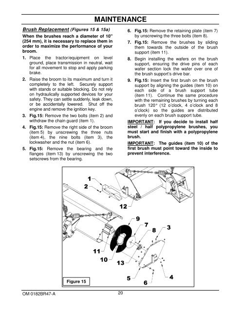
3. Fig.15: Remove the two bolts (item 2) and<br />
withdraw the chain guard (item 1).<br />
4. Fig.15: Remove the right side of the broom<br />
(item 5) by unscrewing the three nuts<br />
(item 4), the nine bolts (item 3), the<br />
lockwasher and the nut (item 6).<br />
5. Fig.15: Remove the bearing and the<br />
flanges (item 13) by unscrewing the two<br />
setscrews from the bearing.<br />
6. Fig.15: Remove the retaining plate (item 7)<br />
by unscrewing the three bolts (item 8).<br />
7. Fig.15: Remove the brushes by sliding<br />
them towards the outside of the brush<br />
support (item 11).<br />
8. Begin installing the wafers on the brush<br />
support, ensuring the drive pins of each<br />
wafer section lock the wafer over one of<br />
the brush support’s drive bar.<br />
9. Fig.15: Insert the first brush on the brush<br />
support by aligning the guides (item 10) on<br />
each side of a brush support tube<br />
(item 11). Continue the same procedure<br />
with the remaining brushes by turning each<br />
brush 120° (12 o’clock, 4 o’clock and 8<br />
o’clock) so the guides are distributed<br />
evenly on each brush support tube.<br />
IMPORTANT: If you decide to install half<br />
steel / half polypropylene brushes, you<br />
must start and finish with a polypropylene<br />
brush.<br />
IMPORTANT: The guides (item 10) of the<br />
first brush must point toward the inside to<br />
prevent interference.<br />
Figure 15<br />
OM 0182BR47-A 20