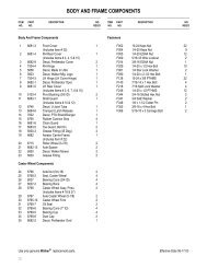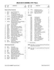
OPERATOR'S AND PARTS MANUAL - Walker Mowers
OPERATOR'S AND PARTS MANUAL - Walker Mowers
OPERATOR'S AND PARTS MANUAL - Walker Mowers

You also want an ePaper? Increase the reach of your titles
YUMPU automatically turns print PDFs into web optimized ePapers that Google loves.
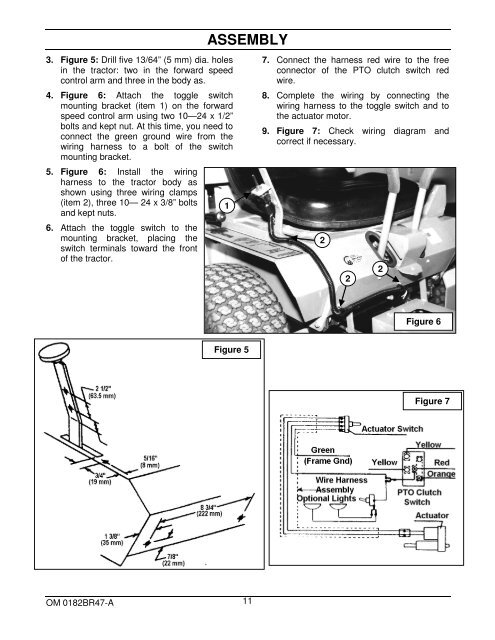
3. Figure 5: Drill five 13/64” (5 mm) dia. holes<br />
in the tractor: two in the forward speed<br />
control arm and three in the body as.<br />
4. Figure 6: Attach the toggle switch<br />
mounting bracket (item 1) on the forward<br />
speed control arm using two 10—24 x 1/2”<br />
bolts and kept nut. At this time, you need to<br />
connect the green ground wire from the<br />
wiring harness to a bolt of the switch<br />
mounting bracket.<br />
5. Figure 6: Install the wiring<br />
harness to the tractor body as<br />
shown using three wiring clamps<br />
(item 2), three 10— 24 x 3/8” bolts<br />
and kept nuts.<br />
6. Attach the toggle switch to the<br />
mounting bracket, placing the<br />
switch terminals toward the front<br />
of the tractor.<br />
ASSEMBLY<br />
1<br />
7. Connect the harness red wire to the free<br />
connector of the PTO clutch switch red<br />
wire.<br />
8. Complete the wiring by connecting the<br />
wiring harness to the toggle switch and to<br />
the actuator motor.<br />
9. Figure 7: Check wiring diagram and<br />
correct if necessary.<br />
2<br />
2<br />
2<br />
Figure 6<br />
Figure 5<br />
Figure 7<br />
OM 0182BR47-A 11