OPERATOR'S AND PARTS MANUAL - Walker Mowers
OPERATOR'S AND PARTS MANUAL - Walker Mowers
OPERATOR'S AND PARTS MANUAL - Walker Mowers

You also want an ePaper? Increase the reach of your titles
YUMPU automatically turns print PDFs into web optimized ePapers that Google loves.
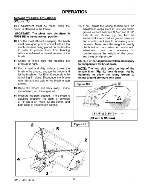
Ground Pressure Adjustment<br />
(Figure 12)<br />
This adjustment must be made when the<br />
broom is attached to the tractor.<br />
IMPORTANT: The pivot lock pin (item 3)<br />
MUST BE in the outermost position.<br />
10. For the most efficient sweeping, the brush<br />
must have good ground contact without too<br />
much pressure being placed on the bristles<br />
in order to prevent them from bending<br />
which would result in premature wear of the<br />
brush.<br />
11. Check to make sure the tractor's tire<br />
pressure is right.<br />
12. Find a hard and dirty surface. Lower the<br />
brush to the ground, engage the broom and<br />
let the brush turn for 15 to 30 seconds while<br />
remaining in place. Disengage the broom<br />
with raising it and wait for the brush to stop<br />
turning.<br />
13. Raise the broom and back away. Once<br />
immobilized, turn the engine off.<br />
14. Measure the path cleaned. If the brush is<br />
adjusted properly, the path is between<br />
3 1/4" and 3 3/4" wide (83 and 95mm) and<br />
both sides of the path are parallel.<br />
OPERATION<br />
15. If not, adjust the spring tension with the<br />
adjustment knobs (item 2) until you obtain<br />
ground contact between 3 1/4" and 3 3/4"<br />
wide (83 and 95 mm) (fig. 5a). Turn the<br />
knobs clockwise to reduce ground pressure<br />
and counter clockwise to increase ground<br />
pressure. Make sure the weight is evenly<br />
distributed on both sides. An asymmetric<br />
adjustment may be necessary to<br />
counterbalance the weight of the broom<br />
and the ground pressure.<br />
NOTE: Further adjustment will be necessary<br />
to compensate for brush wear.<br />
NOTE: The two side bolts on top of the<br />
female hitch (Fig. 12, item 4) must not be<br />
tightened to allow the rotary broom to<br />
follow ground contours with ease.<br />
Figure 12a<br />
Figure 12<br />
(83 mm @ 95 mm)<br />
OM 0182BR47-A 16