1 - FlowVision GmbH
1 - FlowVision GmbH
1 - FlowVision GmbH

Create successful ePaper yourself
Turn your PDF publications into a flip-book with our unique Google optimized e-Paper software.
8<br />
8<br />
8<br />
8<br />
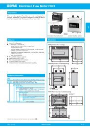
Electronic Flow Meter FC01-Ex-CA (compressed air/gas)<br />
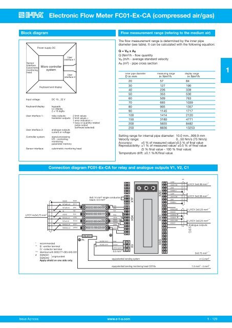
Block diagram<br />
Flow measurement range (refering to the medium air)<br />
Sensor<br />
interface<br />
Calorimetric<br />
monitoring<br />
head<br />
Input voltage:<br />
Keyboard/display:<br />
User interface 1:<br />
User interface 2:<br />
Controller system:<br />
Sensor interface:<br />
Power supply DC<br />
Micro controller<br />
system<br />
Keyboard and display<br />
DC 19…32 V<br />
User<br />
interface 1<br />
User<br />
interface 2<br />
keypads<br />
LC display<br />
2 x 16 digits<br />
relay outputs: 2 limit values<br />
transistor outputs: 2 limit values +<br />
1 error indication +<br />
1 busy or quantity-related<br />
pulse output<br />
(software selected)<br />
analogue outputs<br />
current or voltage<br />
signal processing<br />
I/O - controlling<br />
monitoring<br />
parameter memory<br />
calorimetric monitoring head<br />
The flow measurement range is determined by the inner pipe<br />
diameter (see table). It can be calculated with the following equation:<br />
Q = V N x A R<br />
Q (Nm 3 /h - flow quantity<br />
V N (m/h - average standard velocity<br />
A R (m 2 ) - pipe cross section<br />
inner pipe diameter measuring range display range<br />
D in mm in Nm 3 /h in Nm 3 /h<br />
20 57 84<br />
30 127 190<br />
40 226 339<br />
50 353 530<br />
60 509 763<br />
70 693 1039<br />
80 905 1357<br />
90 1145 1717<br />
100 1414 2120<br />
150 3180 4771<br />
200 5655 8482<br />
250 8836 13253<br />
Setting range for internal pipe diameter: 10.0 mm...999.9 mm<br />
Velocity range:<br />
0...50 Nm/s (75 Nm/s)<br />
Accuracy: ±5 % of measured value/±0.5 % of final value<br />
Reproducibility: ±1 % of measured value/ ±0.5 % of final value<br />
(5 % final value - 100 % final value)<br />
Temperature drift: ±0.1 %/K/final value<br />
1<br />
Connection diagram FC01-Ex-CA for relay and analogue outputs V1, V2, C1<br />
LiYCY 4x2x0,75 mm 2<br />
SGND<br />
R(Tdiff)-LO<br />
R(Tdiff)-HI<br />
IS<br />
AGND<br />
R(Tref)-LO<br />
R(Tref)-HI<br />
R(HEIZ)-HI<br />
R(HEIZ)-LO<br />
black<br />
pin k<br />
gray<br />
red<br />
blue<br />
white<br />
brown<br />
green<br />
yellow<br />
* recommended<br />
** E/ -emitter terminal<br />
C/ -collector terminal<br />
*** identical with 9002/77-093-040-001<br />
# SGNDA1<br />
SGNDA2 }ungrounded<br />
Apply shield on one side only.<br />
3<br />
4<br />
9002/22-032-300-111<br />
4 3<br />
2 1<br />
3<br />
4<br />
/PA<br />
USLKG 5<br />
8x0.14 mm 2 single conductor<br />
black: 0.5 mm 2<br />
9002/22-093-040-001 ***<br />
9002/22-093-040-001 ***<br />
1<br />
2<br />
1<br />
2<br />
9002/13-199-225-001<br />
4 3<br />
2 1<br />
AC/DC 24 V<br />
AC/DC 24 V<br />
pink<br />
grey<br />
red<br />
blue<br />
white<br />
black<br />
brown<br />
green<br />
yellow<br />
blue<br />
brown<br />
yellow/green<br />
0.5 mm 2<br />
1 2 3 4 5 6 7 9 10 1 2 3 1 2 3 4<br />
3<br />
2<br />
1<br />
XV XSK XTF<br />
M<br />
equipotential bonding system<br />
XAS XAO XAH<br />
1 2 3 4 5 6 7<br />
1 2 3 4 5 6 7<br />
1 2 3 4 5 6 7<br />
/LIM2<br />
LIM2COM<br />
LIM2<br />
SGNDL2<br />
/LIM1<br />
LIM1COM<br />
LIM1<br />
SGNDL1<br />
ANA2GND<br />
ANAO2<br />
SGNDA2 #<br />
SGNDA1 #<br />
ANA1GND<br />
ANAO1<br />
**<br />
LiYCY 3x0.38 mm 2 *<br />
LiYCY 3x0.38 mm 2 *<br />
LiYCY 2x0.25 mm 2 *<br />
LiYCY 2x0.25 mm 2 *<br />
Analogue outputs:<br />
V1<br />
V2<br />
C1<br />
2x0.75 mm 2 *<br />
≥1.5 mm 2<br />
equipotential bonding monitoring head CST-Ex<br />
1.5 mm 2 - 4 mm 2<br />
Issue A(270308) www.e-t-a.com<br />
1 - 129