36e Operator's Manual 2012.pdf - Marlow-Hunter, LLC
36e Operator's Manual 2012.pdf - Marlow-Hunter, LLC
36e Operator's Manual 2012.pdf - Marlow-Hunter, LLC

You also want an ePaper? Increase the reach of your titles
YUMPU automatically turns print PDFs into web optimized ePapers that Google loves.
DC Electric<br />
7.2.3 Battery Charging System<br />
Refer to the DC Wiring Diagram drawing at the end of<br />
this section for the location of the battery charger. The<br />
charger is protected by a fuse on the positive and ground<br />
side at the charger.<br />
To operate the charger, ensure that it is operating:<br />
1. Connect the shore power dockside supply shore<br />
power inlet on the stern of the boat on the port side.<br />
2. Turn on AC Main breaker.<br />
3. Turn on the Battery Charger breaker.<br />
7.2.4 12 Volt DC Panel<br />
All electrical systems aboard your boat are provided with<br />
over-current protection in the form of breakers or fuses.<br />
Examples of breakers are the system or component controls<br />
at the 12 Volt Panel, or in the battery selector switch<br />
panel. Systems that would normally require you to energize<br />
them for use are provided with switches.<br />
7.2.6 Inverter (Option)<br />
Inverter converts DC power to AC.<br />
7.2.6.1 Inverter Basic Operation<br />
1. Turn the house battery switch to either the “1, 2 or<br />
Both” positions<br />
2. Turn on inverter remote panel at the Navigation<br />
Station.<br />
OFF<br />
12V DC<br />
RUNNING LIGHTS<br />
ANCHOR LT<br />
3. Turn on the appropriate appliance breaker on AC<br />
Panel. Note: only Outlets and microwave operating using<br />
the inverter.<br />
STEAMING LT<br />
OFF<br />
OFF<br />
WATER PUMP<br />
BLOWER<br />
VOLTS<br />
See Inverter manual for technical data, troubleshooting,<br />
etc. operatiing/programming instructions.<br />
OFF<br />
OFF<br />
MACERATOR<br />
GPS<br />
PANEL<br />
LTS<br />
7.2.7 Generator (Option)<br />
OFF<br />
CABIN LIGHTS<br />
INSTRUMENTS<br />
TV/DVD<br />
BILGE<br />
PUMP<br />
Although, technically, the generator is part of the AC<br />
System, because it supplies AC power, however the starting<br />
of the generator requires DC power. The generator<br />
starting receives power from the start battery bank.<br />
LPG<br />
STEREO<br />
REFRIGERATOR<br />
SUMP PUMP<br />
HEAD<br />
12V OUTLETS<br />
TANK INDICATOR<br />
SPARE<br />
The generator supplies 120 volt 60 hz AC power for<br />
operating devices and equipment controlled through the<br />
AC Control Panel.<br />
Figure 7.2<br />
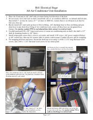
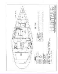
You can view the DC components controlled by the DC<br />
control panel here (Fig. 7.2). Notice when the battery<br />
selector switch is switched on the respective voltage of<br />
the battery is shown on the right by the digital volt meter.<br />
Indicator lights are built into most switches and alert you<br />
that the selected system is powered.<br />
7.2.5 Breakers, Switches, and Fuses<br />
When the generator indicating light is on and the generator<br />
breakers are on, AC power is supplied to AC control<br />
panel devices and equipment.<br />
Refer to the “Operation and Procedures” part of the AC<br />
Electric section for information on starting the generator.<br />
You can find the location of the generator on the DC<br />
Wiring Diagram drawing at the end of this chapter.<br />
7.2.8 Water Systems<br />
The water systems are outlined in the Water Systems<br />
chapter in this manual. However, the monitor for this system<br />
are powered by the DC Electrical system.<br />
7.4