

Nicoll Highway Collapse: Evaluation of Geotechnical ... - Plaxis
Nicoll Highway Collapse: Evaluation of Geotechnical ... - Plaxis
Nicoll Highway Collapse: Evaluation of Geotechnical ... - Plaxis

You also want an ePaper? Increase the reach of your titles
YUMPU automatically turns print PDFs into web optimized ePapers that Google loves.
<strong>Nicoll</strong> <strong>Highway</strong> <strong>Collapse</strong>: <strong>Evaluation</strong> <strong>of</strong> <strong>Geotechnical</strong><br />
Factors Affecting Design <strong>of</strong> Excavation Support System<br />
A.J. Whittle, Massachusetts Institute <strong>of</strong> Technology, Cambridge, MA, USA,<br />
R.V. Davies, Benaim (UK), Bath, UK,<br />
International Conference on Deep Excavations<br />
28-30 June 2006, Singapore<br />
ABSTRACT: This paper summarizes the site characterization, selection <strong>of</strong> soil parameters and analyses<br />
<strong>of</strong> soil-structure interaction that affected the design <strong>of</strong> the support system for the Circle Line Stage<br />
1 excavations at contract C824, adjacent to the <strong>Nicoll</strong> <strong>Highway</strong>. Features <strong>of</strong> the local stratigraphy included<br />
a buried channel in the underlying Old Alluvium which affected directly the installation <strong>of</strong> perimeter<br />
diaphragm wall panels. Surface settlements and pore pressures measured prior to construction<br />
strongly suggest on-going consolidation <strong>of</strong> the Marine Clay due to land reclamation in the 1970’s.<br />
From the evidence available, the Authors concluded that the lower Marine Clay unit was underconsolidated<br />
resulting in a relatively low undrained shear strength <strong>of</strong> the clay in relation to the total overburden<br />
pressure. Uncertainties existed in drainage conditions in the Old Alluvium and despite extensive<br />
post-failure investigations, the installed locations, behavior and mass properties <strong>of</strong> jet grout pilerafts<br />
remain highly uncertain. The original analysis <strong>of</strong> soil-structure interaction was carried out using<br />
nonlinear finite element methods with linearly-elastic, Mohr-Coulomb (MC) models to represent the<br />
soil behavior. The use <strong>of</strong> this soil model together with drained effective stress strength parameters (c’,<br />
φ’), in an undrained setting, greatly overestimated the undrained shear strength <strong>of</strong> the Marine Clay in<br />
the original design leading to a serious underestimation <strong>of</strong> computed wall deflections, bending moments<br />
and the mobilization <strong>of</strong> forces in the JGP pile-rafts.<br />
1 INTRODUCTION<br />
The government <strong>of</strong> Singapore has acted quickly to investigate the causes and contributory factors<br />
leading to the collapse <strong>of</strong> the <strong>Nicoll</strong> <strong>Highway</strong> on April 20 th 2004. The Committee <strong>of</strong> Inquiry report<br />
(COI, 2005) identified two key errors in the design <strong>of</strong> the temporary lateral earth support system for<br />
the adjacent excavation <strong>of</strong> the Circle Line, contract C824: 1) under-design <strong>of</strong> the diaphragm wall due<br />
to the method <strong>of</strong> analyzing soil-structure interaction; and 2) under-design <strong>of</strong> the waler connections in<br />
the strutting system. The Authors contributed to the Committee <strong>of</strong> Inquiry as experts appointed by<br />
LTA. This paper reviews the geotechnical factors leading to the under-design <strong>of</strong> the diaphragm wall.<br />
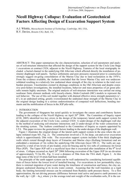
Figure 1 illustrates the original design <strong>of</strong> the lateral earth support system in the area where the collapse<br />
initiated (type M3, Fig. 2). The construction involved a 33.3m deep, cut-and-cover excavation<br />
which is approximately 20m wide. The excavation support system includes 0.8m thick diaphragm<br />
walls which extend through deep layers <strong>of</strong> Estuarine and Marine clays (Kallang formation) and are<br />
embedded a minimum <strong>of</strong> 3m within the underlying Old Alluvium (layer SW-2). The walls are supported<br />
by a total <strong>of</strong> ten levels <strong>of</strong> pre-loaded, cross-lot bracing and by two rafts <strong>of</strong> continuous Jet Grout<br />
Piles (JGP). The Upper JGP raft is a sacrificial layer that is excavated after installation <strong>of</strong> the 9 th level<br />
<strong>of</strong> struts. <strong>Collapse</strong> occurred on April 20 th 2004 following excavation <strong>of</strong> the Upper JGP (to an elevation<br />
<strong>of</strong> approximately 72.3m RL, Fig. 1) over a distance <strong>of</strong> 30m from the TSA shaft, Figure 2. At this<br />
stage none <strong>of</strong> the level 10 struts had been installed.<br />
The principle <strong>of</strong> the earth support system can be well understood by considering horizontal equilibrium<br />
<strong>of</strong> forces below the lowest level <strong>of</strong> installed bracing: For excavations in low permeability clays,<br />
there is minimal migration <strong>of</strong> pore water during the timeframe <strong>of</strong> construction and hence, the clay undergoes<br />
undrained shearing at its in-situ water content. Assuming that the wall translates as a rigid<br />
body, the limiting horizontal stresses can be estimated from Rankine earth pressure theory. To a first<br />
approximation, the net driving pressure (difference between total active and passive earth pressure) on<br />
the wall, Δp ≈ (γH – 4s u ), where γ is the average total unit weight <strong>of</strong> the overburden soils, H is the cur-
ent excavation depth and s u the undrained shear strength <strong>of</strong> the clay (below the excavated grade). For<br />
cases where Δp > 0 (i.e., γH > 4s u – which commonly occurs for deep excavations in s<strong>of</strong>t-medium<br />
clays), the wall must transfer the net earth pressure forces to the overlying bracing system and/or span<br />
between the bracing system and an underlying bearing layer (such as the Old Alluvium, Fig. 1). For<br />
the cut-and-cover sections <strong>of</strong> the Circle Line contract C824, the JGP rafts have been included to increase<br />
the shear strength <strong>of</strong> the materials below the excavated grade and hence, increase the available<br />
passive resistance. The actual design <strong>of</strong> the earth support system was based on non-linear finite element<br />
methods which simulate the mobilization and redistribution <strong>of</strong> the earth pressures, flexure <strong>of</strong> the<br />
wall and strutting system at each stage <strong>of</strong> the excavation.<br />
Figure 1. Cross-section <strong>of</strong> excavation support system, Type M3<br />
(soil pr<strong>of</strong>ile is based on borehole ABH-32)<br />
2 SITE CHARACTERIZATION AND SOIL PROPERTIES<br />
Figure 2 shows the locations <strong>of</strong> the pre- and post-tender boreholes (M and ABH series, respectively),<br />
that were used to establish the site stratigraphy for the cut-and-cover tunnel sections adjacent to the<br />
TSA shaft. The site is located on the west bank <strong>of</strong> the Kallang River south <strong>of</strong> <strong>Nicoll</strong> <strong>Highway</strong> in an<br />
area <strong>of</strong> reclaimed land. The Merdeka bridge, Figure 3, was constructed in 1956 (Hollis-Bee, 1956)<br />
following reclamation <strong>of</strong> the area between Beach Road and <strong>Nicoll</strong> <strong>Highway</strong> in the 1930’s and 1940’s.<br />
Further reclamation south <strong>of</strong> <strong>Nicoll</strong> <strong>Highway</strong> was not completed until 1976. The aerial photo from<br />
1969 confirms that the TSA shaft and adjacent sections <strong>of</strong> the cut-and-cover tunnels (Type M3) are<br />
located beneath the land that was reclaimed during the 1970’s. The characteristic soil pr<strong>of</strong>ile includes<br />
4.5–5.0m <strong>of</strong> fill underlain by 30–35m <strong>of</strong> Kallang formation soil deposits and the Old Alluvium. The<br />
engineering geology <strong>of</strong> these main soil units has been extensively documented by Pitts (1983, 1984).<br />
The underlying Old Alluvium is generally assumed to date from the early Pleistocene and was formed<br />
principally as terrace deposits from a large braided river system that covered much <strong>of</strong> South East Asia
(Gupta et al., 1987). Erosion <strong>of</strong> these deposits produced a network <strong>of</strong> deep paleo-channels within the<br />
Old Alluvium beneath Singapore (Pitts, 1983; Davies, 1984).<br />
The paleo-channels are infilled with more recent units <strong>of</strong> the Kallang formation. Bird et al. (2003)<br />
have recently reviewed the age and origins <strong>of</strong> the Kallang soil deposits based on the history <strong>of</strong> sea<br />
level changes that have occurred during the quaternary period. The formation includes two main units<br />
<strong>of</strong> Marine clay that were formed when the Straits <strong>of</strong> Singapore were inundated, while transitional units<br />
(estuarine, E; and fluvial, F) were formed during periods when the sea level was more than 25m below<br />
its present level. According to Bird et al., 2003), the Lower Marine Clay (LMC) dates from the last<br />
interglacial period (approximately 120,000 years ago), while the Upper Marine Clay (UMC) is a holocene<br />
deposit (formed less than 10,000 years ago).<br />
Figure 2 Plan showing location <strong>of</strong> diaphragm wall panels, 9 th level strutting system and site investigation<br />
Figure 3. Aerial photo <strong>of</strong> project site in 1969<br />
For practical purposes (e.g., estimation <strong>of</strong> undrained shear strength) there is little to distinguish the<br />
lower Estuarine and Marine clay units <strong>of</strong> the Kallang formation (both have plasticity indices, I p = 35-<br />
55%, while the Estuarine has a slightly higher liquid limit, w L = 70-100% than LMC, w L = 65-80%).<br />
However, it is more difficult to define the interface between the lower Kallang units (which include<br />
transitional fluvial units <strong>of</strong> sands and clays, F1 and F2) and the more weathered Old Alluvium. At the<br />
C824 site, most <strong>of</strong> the Old Alluvium is classified as very dense silty sands transitioning with depth to
very stiff to hard, silty clay. The SPT blowcount increases markedly with depth in the Old Alluvium,<br />
ranging from N = 10-20blows/300mm (i.e., blows/foot, bpf) near the upper surface to N > 100bpf<br />
typically over a depth <strong>of</strong> 6m – 10m. In order to simplify the interpretation <strong>of</strong> the local geology it is<br />
convenient to define the top <strong>of</strong> the Old Alluvium based on measured SPT blowcount, N > 30bpf corresponding<br />
to material which can provide adequate toe resistance for the diaphragm wall. Figures 4a<br />
and b show elevation contours <strong>of</strong> the base <strong>of</strong> the Lower Marine Clay (or Estuarine) unit and top <strong>of</strong> the<br />
Old Alluvium at the C824 site (the ground surface is level at 102.9m RL across the site). There is a<br />
well defined channel in the Old Alluvium (Fig. 4b) which extends in a North-South direction across<br />
the line <strong>of</strong> the cut-and-cover tunnels and reaches a maximum depth <strong>of</strong> 42m close to the TSA shaft. At<br />
this same location the Lower Marine Clay extends to a depth <strong>of</strong> approximately 40m. The Old Alluvium<br />
rises progressively moving westwards along the tunnel alignment (types M3 and M2), while the<br />
Marine Clay remains deeper along the southern side <strong>of</strong> the tunnels. More detailed observations <strong>of</strong> the<br />
borings indicate transitional fluvial sand units (F1) between the Old Alluvium and Marine Clay on the<br />
North side <strong>of</strong> the tunnels, and fluvial clay units (F2) on the South side.<br />
a) Contours <strong>of</strong> base <strong>of</strong> Lower Marine Clay (m RL)<br />
b) Contours showing top <strong>of</strong> Old Alluvium (N > 30bpf)<br />
Figure 4. Elevation contours derived from pre- and post-tender borehole data<br />
The elevation contours affect the construction <strong>of</strong> the lateral earth support in two key respects: i) The<br />
installation depth <strong>of</strong> diaphragm wall panels should ensure adequate embedment in the Old Alluvium to<br />
achieve toe fixity. The original intent <strong>of</strong> the design was to achieve 3m embedment within the Old Alluvium<br />
(Fig. 1). However, construction records show that the individual panels <strong>of</strong> the diaphragm wall<br />
were actually installed to specified design elevations rather than embedment requirements, Figure 5.<br />
Indeed, several panels have embedment depths less than 1m within the Old Alluvium (with N ><br />
30bpf). ii) Continuity <strong>of</strong> the JGP raft depends on achieving a specified diameter for each the individ-
ual jet grout piles. Field tests in the Upper Marine Clay were used to select the jetting parameters to<br />
achieve 2m diameter jet grout columns. The columns will be much smaller if jetting is carried out<br />
within stronger layers such as the fluvial deposits and weathered Old Alluvium below the Marine<br />
Clay. There were no systematic records <strong>of</strong> the installed elevations <strong>of</strong> the JGP layers at the site. According<br />
to the design elevations, the lower JGP is installed below the Marine Clay units on the North<br />
Wall west <strong>of</strong> panel M303 and is likely to be discontinuous for sections at the boundary between design<br />
sections M2 and M3 (Fig. 2).<br />
Elevation (m RL)<br />
78 M212 M306 M307 M308 M309 M310 M313<br />
76<br />
74<br />
Base <strong>of</strong> Marine Clay<br />
72<br />
70<br />
68<br />
66<br />
64<br />
62<br />
60<br />
58<br />
56<br />
54<br />
52<br />
50<br />
66kV crossing<br />
Top <strong>of</strong> OA<br />
(N>30bpf)<br />
69.4mRL<br />
s<strong>of</strong>t grey<br />
marine clay<br />
inclinometer (I104)<br />
Lower JGP<br />
35 30 25 20 15 10 5 0<br />
Distance Along Diaphragm Wall from TSA Shaft<br />
3m<br />
M301 M302 M303 M304 M305 M312<br />
Top <strong>of</strong> OA (N>30bpf)<br />
Inclinometer (I65)<br />
a) South diaphragm wall<br />
b) North diaphragm wall<br />
Figure 5. Summary <strong>of</strong> as-built diaphragm wall panel embedment in M3 area<br />
Elevation (m RL)<br />
80<br />
78<br />
76<br />
74<br />
72<br />
70<br />
68<br />
66<br />
64<br />
62<br />
60<br />
58<br />
56<br />
54<br />
52<br />
50<br />
66kV cable crossing<br />
Base <strong>of</strong> Marine Clay<br />
Lower JGP<br />
35 30 25 20 15 10 5 0<br />
Distance Along Diaphragm Wall from TSA Shaft<br />
3m<br />
A series <strong>of</strong> piezometer installations provided limited data for interpreting the pore pressures within<br />
the Marine Clay and Old Alluvium units prior to the start <strong>of</strong> construction. The groundwater table in<br />
the Fill ranges from 100.0mRL – 100.5mRL, while data from boreholes MC3010 and M2064 (Figs. 2,<br />
3) indicate a small excess piezometric head, H = 102m – 103mRL below the Marine Clay. Ground<br />
surface settlements were also monitored along the alignment (SM, Fig. 3) over a period <strong>of</strong> about 15<br />
months (June 2000 – October 2001). The majority <strong>of</strong> these markers are located close to the 1969<br />
shoreline and measure settlements less than 10mm over the monitoring period, Figure 6. However,<br />
settlements <strong>of</strong> more than 50mm have been measured at points located below the more recent fill (notably<br />
SM13). These data suggest the possibility <strong>of</strong> on-going consolidation within the Marine Clay almost<br />
30 years after land reclamation. The reference in situ vertical effective stress pr<strong>of</strong>ile, σ’ v0 , used<br />
throughout this paper is based on the assumption <strong>of</strong> a constant piezometric H = 103m throughout the<br />
LMC and OA units.<br />
10<br />
Reference Time: June 12, 2000<br />
0<br />
-10<br />
Settlement (mm)<br />
-20<br />
-30<br />
-40<br />
-50<br />
Line<br />
Point<br />
SM1<br />
SM2<br />
SM3<br />
SM4<br />
SM5<br />
SM6<br />
SM7<br />
SM8<br />
SM9<br />
SM10<br />
SM11<br />
SM12<br />
SM13<br />
-60<br />
1-Jun 1-Aug 1-Oct 1-Dec 1-Feb 1-Apr 1-Jun 1-Aug 1-Oct<br />
Monitoring Dates (2000 - 2001)<br />
Figure 6. Ground surface settlements measured prior to construction<br />
The design <strong>of</strong> the temporary lateral earth support system was based on a table <strong>of</strong> geotechnical design<br />
parameters (GIM, August 2001). This table includes the unit weights, K 0 coefficients, hydraulic<br />
conductivities, k, elastic moduli, E, and both the Mohr-Coulomb (drained) effective stress strength pa-
ameters (c’, φ’) and undrained shear strength pr<strong>of</strong>iles, s u (z) (for all except the F1 unit) for all <strong>of</strong> the<br />
main soil units and JGP layers. Many <strong>of</strong> these parameters were based on prior experience (e.g., Bo et<br />
al., 2003; Tan et al., 2003; Chiam et al., 2003; Li & Wong, 2001). For example, the design elastic<br />
moduli, E [kPa] = 400s u and 2000N in the low permeability Kallang and Old Alluvium units, respectively.<br />
The critical parameters for design purposes are the undrained shear strength pr<strong>of</strong>ile <strong>of</strong> the Marine<br />
Clay, strength parameters and drainage conditions in the Old Alluvium. There are also significant<br />
uncertainties in evaluating the properties <strong>of</strong> the JGP rafts. Although UCS tests on core samples measure<br />
strengths much higher than those assumed in design, the mass performance <strong>of</strong> the raft depends on<br />
the continuity between individual jet grouted piles.<br />
2.1 Marine Clay<br />
There were three main sources <strong>of</strong> undrained shear strength data for the Marine Clays; 1) undrained<br />
triaxial shear tests (CIU type, with K 0 = 1.0), 2) in situ field vane shear tests, and 3) continuous piezocone<br />
penetration resistance data (these data were apparently not considered in GIM, 2001). Although<br />
the CIU tests were used to define the drained effective stress strength parameters (c’ = 0kPa and φ’ =<br />
22° and 24° for the Upper and Lower Marine Clay, respectively), they are not a reliable source <strong>of</strong> information<br />
on the in situ undrained strength ratio, s u /σ’ v (which is affected significantly by the in situ<br />
K 0 condition). There was a large scatter in the field vane data, s uFV , which included some very low<br />
measurements <strong>of</strong> undrained shear strengths in the LMC unit. The interpretation <strong>of</strong> these data is further<br />
complicated by the practice <strong>of</strong> selecting correction factors in estimating design strengths (i.e., the design<br />
strength, s u = µs uFV , where the correction factor µ[I P ] was first proposed by Bjerrum, 1973).<br />
Piezocone penetration records provide a more reliable source <strong>of</strong> information on the undrained shear<br />
strength pr<strong>of</strong>ile in the low permeability clay units. The undrained strength can be correlated to the net<br />
tip resistance, (q T -σ v0 ), through an empirical cone factor, N kT :<br />
s u = (q T – σ v0 )/N kT (1)<br />
where q T is the measured cone resistance (corrected to account for differential pore pressures acting<br />
around the surface <strong>of</strong> the conical tip), and σ v0 is the total overburden pressure.<br />
The cone factor is best estimated through empirical correlations with reference measurements <strong>of</strong><br />
undrained shear strength from (high quality) laboratory laboratory tests measured in different modes <strong>of</strong><br />
shearing (triaxial compression, triaxial extension and direct simple shear). Tan et al. (2003) proposed<br />
N kT = 12 for the Marine Clay based on correlations with laboratory tests at two other sites in Singapore,<br />
while the various experts contributing to the COI assumed N kT = 12 – 14. These values are well<br />
within the range <strong>of</strong> empirical correlations presented by Lunne et al. (1997). Figure 7 compares the<br />
undrained strength pr<strong>of</strong>iles interpreted from 4 piezocone tests in the M3 area assuming N kT = 14. The<br />
tests show very consistent agreement in both the Upper and Lower Marine Clay units, while AC-3<br />
gives substantially high shear strengths than the other three for the UMC layer.<br />
The undrained shear strength ratio <strong>of</strong> the normally consolidated Marine Clay is usually assumed to<br />
be; s u /σ’ v0 = 0.21 (for the direct simple shear mode <strong>of</strong> shearing; Tan et al., 2003). Figure 7 shows that<br />
this strength ratio is consistent with the interpreted piezocone strengths at elevations 86 - 94mRL and<br />
75 - 80mRL, based on the estimated pr<strong>of</strong>ile <strong>of</strong> the current vertical effective stress (Fig. 7b). However,<br />
the data also suggest that the Lower Marine Clay below 75mRL is weaker than this expected strength<br />
pr<strong>of</strong>ile. The interpreted strength at the base <strong>of</strong> the LMC unit (at 63mRL), s u = 47kPa, is more than<br />
10kPa less than the undrained shear strength expected for the normally consolidated clay. This behavior<br />
can be attributed to one or more <strong>of</strong> the following factors: i) the Lower Marine Clay should be<br />
described has a lower undrained strength ratio than the overlying units. There is no direct experimental<br />
basis for this assumption. ii) The Lower Marine Clay is underconsolidated locally (i.e., has not fully<br />
consolidated under the 5m fill placed in the 1970’s). This implies that the piezometric pressures in the<br />
Lower Marine Clay are higher than 103mRL and could explain the surface settlements shown in Figure<br />
6. It also implies that there is no seepage into the underlying Old Alluvium (i.e., there is one way<br />
upward drainage within the LMC). iii) Undrained shear strength in the LMC is underestimated using<br />
N kT =14. There is no direct basis for refining the selection <strong>of</strong> N kT , the current choice produces consistent<br />
interpretation <strong>of</strong> the design s u pr<strong>of</strong>ile above 75mRL. The GIM (2001) design table assumes that<br />
the Marine Clay is normally consolidated below a depth <strong>of</strong> 15m and hence, potentially overestimates<br />
the undrained shear strength by up to 10-15kPa. There were no reliable stress history data obtained<br />
from the pre- and post-tender site investigations. However, data from the post-collapse investigations<br />
(at boreholes outside the zone <strong>of</strong> the collapse), Fig. 7b, confirm that the Marine Clay is normally con-
solidated below a depth <strong>of</strong> 10m, and the transition fluvial unit (F2) is lightly overconsolidated. Figure<br />
7 shows the Authors‘ best estimate <strong>of</strong> the undrained strength pr<strong>of</strong>ile in the M3 area.<br />
Figure 7. Undrained shear strength <strong>of</strong> Marine Clay, Section M3<br />
2.2 Old Alluvium<br />
The drainage properties <strong>of</strong> the Old Alluvium have important practical implications in the design <strong>of</strong><br />
the lateral earth support system. The upper 5-10m <strong>of</strong> the Old Alluvium are weathered (zones W, SW-2<br />
and SW-1) and generally classified as silty sands or silty clays (although there are locations which include<br />
hard clays layers). These materials are generally more permeable than the underlying intact<br />
material (cemented zone, CZ), or the overlying Marine Clay (k = 10 -9 m/sec; GIM, 2001). The original<br />
table <strong>of</strong> design parameters quoted values <strong>of</strong> permeability, k = 5x10 -7 and 5x10 -8 m/sec for the weathered<br />
OA layers and intact CZ layer, respectively. In comparison, Li and Wong (2001) report k = 10 -9 –<br />
10 -10 m/sec for intact Old Alluvium. Overall, these data suggest that recharge <strong>of</strong> pore pressures below<br />
the base <strong>of</strong> the excavation depends on lateral seepage and hence, depends on the extent and continuity<br />
<strong>of</strong> the weathered more permeable OA deposits (and overlying fluvial sands, F1).<br />
The original design assumed that the weathered OA layers were free draining materials with pore<br />
pressures (below the base <strong>of</strong> the excavation) controlled by the excavated grade elevation. This condition<br />
can only be achieved in practice if the diaphragm walls form a hydraulic cut-<strong>of</strong>f (i.e., extend into<br />
the intact OA material) and relief wells are installed through the JGP to reduce uplift pressures in the<br />
weathered OA. In practice, the embedment <strong>of</strong> the diaphragm walls is not sufficient to ensure hydraulic<br />
isolation below the base <strong>of</strong> the excavation (cf. Fig. 5). However, the assumption <strong>of</strong> free draining conditions<br />
is highly unrealistic and would imply no reduction in the pore pressures below the base <strong>of</strong> the<br />
excavation (i.e., there is full recharge). This condition would lead to premature basal failure through<br />
hydraulic uplift.<br />
Our own investigations suggest that very little migration <strong>of</strong> pore water is likely to occur within the<br />
time frame <strong>of</strong> the excavation and hence, it is more reasonable to assume undrained shearing conditions<br />
within the weathered OA (the undrained shear strength <strong>of</strong> the Old Alluvium can then be estimated using<br />
empirical correlations, s u (kPa) = 5N(bpf) as proposed by GIM, 2001). According to this scenario,
significant reductions in pore pressures should occur in the Old Alluvium. The magnitude <strong>of</strong> pore<br />
pressure change can be estimated using the well known Skempton pore pressure parameters, A and B:<br />
Δu = BΔσ 3 + AB(Δσ 1 -Δσ 3 ) (2)<br />
where Δσ 1 and Δσ 3 are the changes in (major and minor principal) total stresses due to the excavation<br />
(the ratio Δσ 3 / Δσ 1 will depend on the depth to width <strong>of</strong> the excavation, for a very wide excavation 1-<br />
D generate Δσ 3 = 0 and Δσ 1 = Δσ v ). For saturated soils, it is generally assumed that B = 1.0 while the<br />
parameter A depends on soil shear properties. For elastic unloading, A = 0.5, hence the change in pore<br />
pressure expected beneath the center <strong>of</strong> the excavation Δu ≤ 0.5Δσ v .<br />
Partial drainage within the Old Alluvium can be evaluated directly by monitoring pore pressures<br />
within the Old Alluvium. Unfortunately, there was only one piezometer installed beneath the excavation<br />
within the weathered OA material in the M3 area (GWV-24 located close to the north diaphragm<br />
wall at 64mRL). This device measured Δu = 0.25 – 0.30Δσ v (where Δσ v is the 1-D vertical stress relief)<br />
for excavation to 82 mRL (i.e, to strut level 6, Fig. 1), but was ineffective thereafter. Finite element<br />
simulations <strong>of</strong> these data are consistent with the assumption <strong>of</strong> undrained conditions.<br />
3 ANALYSIS OF SOIL-STRUCTURE INTERACTION<br />
3.1 Method and Assumptions<br />
The design <strong>of</strong> the lateral earth support system for Contract 824 was based directly on results <strong>of</strong> nonlinear<br />
Finite Element (FE) analyses using the <strong>Plaxis</strong> program (v7.2). This program is capable <strong>of</strong> modeling<br />
response <strong>of</strong> the continuous ground mass (deformations and groundwater seepage) and interactions<br />
with the structural support elements (perimeter wall, preloaded cross-lot struts) in two dimensions.<br />
At each stage <strong>of</strong> a simulated construction schedule, the numerical analyses generate information<br />
on the bending moments and deflections <strong>of</strong> the perimeter diaphragm wall, axial strut forces, ground<br />
deformations and pore pressures. By representing the complex stress changes within the soil mass<br />
during an excavation (arching mechanisms etc.), 2-D FE programs such as <strong>Plaxis</strong> represent a major in<br />
advance in analysis capabilities compared to conventional 1-D (FE) models <strong>of</strong> support systems (e.g.,<br />
Wallap, Geosolve, 2002; Kasetsu-5x, CRCRI, 1999). However, effective utilization <strong>of</strong> these capabilities<br />
requires: a) careful specification <strong>of</strong> boundary and initial conditions (in situ soil stresses and<br />
groundwater conditions), b) selection <strong>of</strong> soil models with appropriate input parameters to represent engineering<br />
properties <strong>of</strong> the pertinent soil layers (shear strength, stiffness parameters and permeability);<br />
and c) methods for interpreting and evaluating predictions <strong>of</strong> the analyses. There also remains a major<br />
question regarding the appropriate use <strong>of</strong> finite element methods in the design <strong>of</strong> excavation support<br />
systems particularly in the definition <strong>of</strong> ‘worst credible’ or ‘moderately conservative’ ground (soil and<br />
groundwater properties) and loading conditions (as discussed by Simpson & Yazdchi, 2003).<br />
The default mode <strong>of</strong> calculation used by <strong>Plaxis</strong> treats soil as a two phase medium comprising the<br />
soil skeleton and interstitial pore water (it is also possible to model single phase, ‘non-porous’ materials).<br />
The <strong>Plaxis</strong> program follows conventional geotechnical design calculations which assume simplified<br />
drainage conditions (i.e., flow <strong>of</strong> groundwater) within soil layers. Low permeability clays are<br />
treated as undrained materials (i.e., there is no migration <strong>of</strong> pore water within the skeleton over the<br />
time frame <strong>of</strong> interest), while more permeable sands are considered fully drained (i.e, pore pressures<br />
are always in a steady state condition - as groundwater flow can occur rapidly relative to the timeframe<br />
<strong>of</strong> interest). Time dependent deformations due to consolidation (or creep) can also be simulated in<br />
<strong>Plaxis</strong>. Although consolidation can contribute significantly to the interpretation <strong>of</strong> ground settlements<br />
around a braced excavation in s<strong>of</strong>t clay (i.e., in the interpretation <strong>of</strong> field performance), the current design<br />
appropriately ignores consolidation in the design <strong>of</strong> the excavation support system.<br />
<strong>Plaxis</strong> <strong>of</strong>fers a range <strong>of</strong> constitutive models <strong>of</strong> varying complexity to characterize the deformation<br />
and shear strength properties <strong>of</strong> soil layers. The default model is referred to as a linearly Elastic-<br />
Perfectly Plastic model (EPP) – which has four basic input parameters: The pre-failure stiffness <strong>of</strong> the<br />
soil is characterized by two elastic properties (E’ , Young’s modulus; and ν’, Poisson’s ratio) while the<br />
shear strength is described by the conventional Mohr-Coulomb criterion. The undrained shear strength<br />
<strong>of</strong> the clay can be represented either using A) effective stress, strength parameters (c’, apparent cohesion;<br />
and φ’, internal friction angle); or B) undrained shear strengths (c’ → s u ; φ’ = 0°). These ap-
proaches are referred to as Methods A and B in the COI report (COI, 2005) and the subsequent discussions.<br />
The EPP model is almost universally accepted as the base level representation <strong>of</strong> soil behavior suitable<br />
for design. More advanced models (notably ‘Hardening Soil’, Schantz et al., 2000) are also available<br />
within <strong>Plaxis</strong> and can describe more realistically the non-linear stress-strain properties <strong>of</strong> real<br />
soils. Although these models can improve the predictive capability <strong>of</strong> FE analyses (this is especially<br />
helpful in interpreting field performance measurements), they introduce additional material parameters<br />
and require more extensive calibration <strong>of</strong> soil properties. Although the use <strong>of</strong> such models would certainly<br />
have been justified based on the size and importance <strong>of</strong> this project, it is clearly beyond the<br />
scope <strong>of</strong> soil data available from the (pre- and post-tender) site investigation that was actually carried<br />
out.<br />
According to the EPP model, there is no change in mean effective stress during undrained shearing<br />
(i.e,. there are no shear-induced pore pressures and hence, Δu = Δσ oct where σ oct = 1/3[Δσ 1 + Δσ 2 + Δσ 3 ]<br />
is the mean total stress). For undrained triaxial compression tests with Δσ 3 = 0, A = 0.33 (eqn. 2),<br />
while all undrained plane strain, shear modes are characterized by A = 0.5. Figure 8 illustrates the effective<br />
stress path (A’-B’) for undrained plane strain shearing. It is clear that the undrained shear<br />
strengths according to Methods A and B are interrelated as follows:<br />
s u = c’cosφ’ +1/2(σ’ 1 +σ’ 3 )sinφ’<br />
Assuming that the initial state <strong>of</strong> stress is defined by K 0 conditions in the ground, then Method A implies<br />
that the undrained strength ratio is given by:<br />
s u / σ’ v0 = (c’/σ’ v0 )cosφ’ +1/2(1+K 0 )sinφ’<br />
where σ’ v0 is the initial vertical effective stress at a given depth in the ground.<br />
(3a)<br />
(3b)<br />
Figure 8. Effective stress path for undrained plane strain shearing using EPP (Mohr-Coulomb) soil model<br />
There is extensive empirical information relating the undrained shear strength to the stress history <strong>of</strong><br />
sedimentary clays. The most widely used correlations (e.g., SHANSEP; Ladd and Foott, 1974) relate<br />
the undrained strength ratio s u /σ’ v to the overconsolidation ratio, OCR = σ’ p /σ’ v , where σ’ p is the vertical<br />
pre-consolidation pressure. For example, Figure 9 shows an expected correlation for the Singapore<br />
Marine Clay based on S = s u /σ’ v = 0.21 for the normally consolidated case (OCR = 1.0; Fig. 7). The<br />
Figure also shows the undrained shear strength obtained in plane strain analyses using Method A with<br />
the effective stress strength parameters that were used in the original design (i.e., c’ = 0kPa and φ’ =<br />
22°, 24° for UMC and LMC, respectively), together with well known empirical correlations for K 0 . It<br />
is clear that Method A overestimates the undrained shear strength for normally and lightly overconsolidated<br />
clay (OCR < 2), but is generally conservative at higher OCR.<br />
The practical consequence <strong>of</strong> using the EPP with Method A is most clearly seen in Figure 7 which<br />
shows the undrained shear strength pr<strong>of</strong>ile that was implicitly used in the finite element design analyses.<br />
The undrained shear strength is much larger than the original design line (GIM, 2001), particularly<br />
in the Lower Marine Clay. In contrast, Method B uses the undrained strength pr<strong>of</strong>ile directly in<br />
the finite element analyses and is certainly the most reliable way to use the EPP model for simulating<br />
undrained behavior <strong>of</strong> clays for Contract 824. The potential disadvantage <strong>of</strong> Method B is that the<br />
shear strength is no longer a function <strong>of</strong> effective stress and hence, changes in shear strength due to<br />
consolidation (partial drainage) are no longer represented. This limitation is mute for design calculations<br />
that assume undrained conditions (through the timeframe <strong>of</strong> an excavation), but can be a serious<br />
limitation when modeling problems where consolidation deformations are significant.
Figure 9. Comparison <strong>of</strong> the undrained strength ratio for the Marine Clay using Method A with empirical correlations<br />
based on SHANSEP<br />
3.2 Effect <strong>of</strong> Analysis Method and Undrained Strength Pr<strong>of</strong>ile on Design<br />
A series <strong>of</strong> finite element simulations have been carried out (using <strong>Plaxis</strong> v8.2) to investigate the role<br />
<strong>of</strong> the analysis method (A vs B) and selection <strong>of</strong> undrained strength pr<strong>of</strong>ile on the type M3 design <strong>of</strong><br />
the temporary lateral earth support system. This section illustrates results from 4 <strong>of</strong> these calculations<br />
with characteristic properties as follows:<br />
• A[NLC] is a calculation that reproduces the original design assumptions. The undrained shear<br />
strength <strong>of</strong> the Marine and Estuarine Clay units are based on the use <strong>of</strong> effective stress<br />
strength parameters (c’, φ’) provided by GIM (2001) according to Method A. The corresponding<br />
undrained shear strength pr<strong>of</strong>ile is shown in Figure 10. The weathered Old Alluvium<br />
(SW-2) is assumed to be free draining with pore pressures defined by the current excavation<br />
grade elevation (as per the original design). The analyses also uses the initial K 0 , soil<br />
stiffness and JGP properties prescribed by GIM (2001).<br />
• B[GIM] uses Method B (s u , φ’ = 0°) to represent the undrained strength pr<strong>of</strong>ile for the Marine<br />
and Estuarine clay layers.<br />
• GIM* also uses Method B, but makes three amendments that are consistent with our interpretation<br />
<strong>of</strong> local ground conditions: i) the lower Estuarine unit has the same undrained strength<br />
pr<strong>of</strong>ile as the Lower Marine Clay (s u /σ’ v = 0.21); ii) the weathered Old Alluvium (SW-2) is<br />
undrained with strength properties related to the SPT data according to GIM (2001); and iii)<br />
the lower JGP was constructed to a design thickness <strong>of</strong> 2.6m (as compared to 3.0 assumed in<br />
the design analyses).<br />
• EBC makes one further modification to the previous case (GIM*), by introducing an improved<br />
estimate <strong>of</strong> the undrained strength pr<strong>of</strong>ile in the Lower Marine Clay (EBC; Fig. 10) based on<br />
the interpretation <strong>of</strong> piezocone data presented in Figure 7.
Figure 10. Undrained strength pr<strong>of</strong>iles used in FE simulations for Type M3 excavation support system<br />
Figure 11. Effect <strong>of</strong> undrained shear strength pr<strong>of</strong>ile on wall deflections for Type M3 excavation support system<br />
Figures 11a and b compare predictions <strong>of</strong> the lateral wall deflections from these analyses for excavation<br />
to the 7 th level struts (81.6 mRL) and final formation level (69.6 mRL), respectively. The results<br />
show the following:<br />
Wall deflections computed by Method B are approximately a factor <strong>of</strong> 2 larger than those computed<br />
using Method A. There is a similar difference in the magnitude <strong>of</strong> the bending moments computed<br />
from the two analyses. The two Methods predict very similar deflection mode shapes at level 7 (Fig.<br />
11a) with maximum deflections occurring at 81m RL. However, quite different mode shapes develop
as the excavation proceeds to level 10 (Fig. 11b). Both analyses predict minimal change in the maximum<br />
wall deflection (100mm and 210mm for A and B, respectively) for excavations below level 7.<br />
This behavior can be understood through further comparison <strong>of</strong> results from B[GIM] and GIM*.<br />
These two cases show very similar wall deflections at level 7. However, GIM* predict a significant<br />
increment in wall deflection below 81mRL for excavation to the final formation. This behavior reflects<br />
the refinement in the selection <strong>of</strong> undrained strength properties in the lower Estuarine and Old<br />
Alluvium (SW-2) layers and the full mobilization <strong>of</strong> the resistance <strong>of</strong> the lower JGP.<br />
The EBC case can be interpreted as a worst credible interpretation <strong>of</strong> the undrained shear strength<br />
pr<strong>of</strong>ile as it implies underconsolidation <strong>of</strong> the Lower Marine Clay. Figure 11a shows that the EBC<br />
pr<strong>of</strong>ile generates an additional 50mm <strong>of</strong> wall deflection at level 7 and up to 90mm additional deflection<br />
at the final formation elevation. These results confirm that small variations in the undrained shear<br />
strength within the LMC (and lower E) layers can produce significant changes in computed wall deflections.<br />
The same set <strong>of</strong> analyses have been used to investigate the mobilization <strong>of</strong> the passive resistance<br />
within the JGP layers. Figure 12a compares the predicted axial force (F x ) in the upper and lower JGP<br />
layers with the design load capacities using Methods A and B as functions <strong>of</strong> the excavation depth.<br />
(with formation elevation for levels 2-9). The computed loads are compared with the design capacity<br />
based on the theoretical passive earth pressures stresses (JGP has design s u = 300kPa). The Figure<br />
presents results for analysis case A (2.6m thick lower JGP) and B[GIM*]. The results show very<br />
clearly that Method B mobilizes the passive resistance <strong>of</strong> the JGP layers at much higher formation elevations<br />
than Method A. For the lower JGP, Method B predicts that the design capacity becomes fully<br />
mobilized for excavation below level 6, while Method A calculations show this condition only occurs<br />
below level 9.<br />
Formation Elevation, RL (m)<br />
100<br />
95<br />
90<br />
85<br />
80<br />
Upper<br />
JGP<br />
(1.5m)<br />
Theoretical Design<br />
Capacity<br />
Lower<br />
JGP (2.6m)<br />
M3-Design Analyses<br />
A<br />
B[GIM*]<br />
M3-Design Analyses<br />
A Upper<br />
Lower<br />
B[GIM*] Upper<br />
Lower<br />
75<br />
0 1000 2000 3000 4000<br />
Horizontal Force in JGP, F x<br />
(kN/m)<br />
0 50 100 150 200 250<br />
Axial Compression <strong>of</strong> JGP (mm)<br />
Notes: The theoretical horizontal passive earth pressure, σ h = σ v + xs u , where x= 2.0 – 2.3 depending on the wall<br />
adhesion.<br />
Figure 12. Effect <strong>of</strong> analysis method on mobilization <strong>of</strong> passive capacity <strong>of</strong> JGP layers<br />
Mobilization <strong>of</strong> the passive resistance <strong>of</strong> the JGP layers is correlated with the axial compression and<br />
hence, can be conveniently compared to measurements <strong>of</strong> wall deflection. Figure 12b presents the corresponding<br />
axial compression <strong>of</strong> the upper and lower JGP layers computed using Methods A and<br />
B[GIM*]. Method B shows significant deviation from Method A predictions <strong>of</strong> axial compression<br />
below level 3 for the Upper JGP and below level 6 for the lower JGP layers, respectively.<br />
Figure 13 summarizes the maximum computed loads in strut levels 6, 7 and 9 during the excavation<br />
for the four analysis cases described above (level 8 was not included as the strut was designed for<br />
maximum loads occurring during subsequent tunnel construction). These calculations incorporated the<br />
theoretical axial load and bending moment capacities <strong>of</strong> the struts and diaphragm wall used in the
Type M3 design. Method B predicts higher loads in strut levels 6 and 7 than Method A, due to differences<br />
in the undrained shear strength <strong>of</strong> the Marine Clay units. However, ironically the level 9 load is<br />
slightly higher for Method A than for Method B. This result is apparently due to compensating errors<br />
in the undrained hear strength assumed in the lower Estuarine unit (see su pr<strong>of</strong>iles for A[NLC] and<br />
B[GIM] in Fig. 10). The computed loads in level 9 (as well as levels 6 and 7) struts increase significantly<br />
for the GIM* and EBC analysis cases. The Method B calculations (GIM, GIM*, EBC) all predict<br />
yielding <strong>of</strong> the diaphragm wall for excavation below 81mRL. The calculations for the worst case<br />
soil pr<strong>of</strong>ile (EBC) generate struts loads very close to the design capacity <strong>of</strong> both level 6 and level 9<br />
struts. The strut load in the level 9 struts is expected to exceed 2000kN/m from all four analysis cases<br />
and hence, exceeds the installed capacity <strong>of</strong> the strut-waler connection.<br />
Strut Load (kN/m)<br />
3000<br />
2500<br />
2000<br />
1500<br />
1000<br />
500<br />
Level 6<br />
Level 7<br />
Level 9<br />
Ultimate Capacity<br />
Level 7, 9<br />
Peak Capacity<br />
Level 9<br />
Strut-Waler<br />
Ultimate Capacity<br />
Level 6<br />
0<br />
A[NLC] B[GIM] GIM* EBC<br />
Undrained Strength Pr<strong>of</strong>ile<br />
Figure 13. Effect <strong>of</strong> the analysis method and undrained shear strength pr<strong>of</strong>ile on computed strut loads<br />
The overall stability <strong>of</strong> the excavation can be evaluated in <strong>Plaxis</strong> using the c-φ reduction technique<br />
(Brinkgreve & Bakker, 1991). This method obtains directly the partial factor <strong>of</strong> safety on soil shear<br />
strength (‘mobilization factor’):<br />
FS = tanφ’/tanφ’ red = c’/c’ red = s u /s ured (4)<br />
where φ’, c’ and s u are the input shear strength parameters, and the subscript ‘red’ refers to reduced<br />
values <strong>of</strong> these parameters necessary to generate a failure mechanism in the FE model.<br />
According to BS8002, the partial factors on the shear strength parameters, FS = 1.2 for parameters<br />
c’ and tanφ’, while FS = 1.5 for s u . The results for Method A show FS = 1.14 for excavation to the final<br />
formation level, while all method B analyses generate FS < 1.3 for excavation to the level 9 struts<br />
(the worst case EBC pr<strong>of</strong>ile produces FS = 1.12). No overall stability calculations were presented for<br />
the original design.<br />
None <strong>of</strong> the preceding calculations have included the actual/installed capacity <strong>of</strong> the strut-waler<br />
connection at level 9. Our investigations found that collapse <strong>of</strong> the <strong>Nicoll</strong> <strong>Highway</strong> occurred due to<br />
the inability <strong>of</strong> the excavation support system to redistribute loads after failure <strong>of</strong> the 9 th level strutwaler<br />
connection. Figure 14 illustrates the role <strong>of</strong> the analysis method on the ability <strong>of</strong> the support<br />
system to redistribute loads after failure <strong>of</strong> the 9 th level <strong>of</strong> struts. The analyses simulate excavation<br />
down to the depth reached on April 20 th 2004 (72.3 mRL) and then evaluate the stability if the 9 th level<br />
<strong>of</strong> struts is removed (i.e., full s<strong>of</strong>tening <strong>of</strong> the strut-waler connection). Figure 14a shows the wall deflections<br />
and strut loads from Methods A and B[GIM], while Figure 14b shows the bending moment<br />
envelope prior to failure <strong>of</strong> the 9 th level waler and the subsequent bending moment diagrams. It should<br />
be noted that Method B generates larger bending moments in the preceding stages <strong>of</strong> excavation than<br />
Method A, exceeding the design wall capacity and enabling potential hinge formation (between 8
8mRL and 78 mRL on the excavated side and at RL 68 mRL on the retained side). Removal <strong>of</strong> the 9 th<br />
level strut causes the following events:<br />
1. Both Methods A and B predict formation <strong>of</strong> two plastic hinges (RL 73m and RL 79m) with<br />
large wall toe rotation.<br />
2. Method B predicts failure <strong>of</strong> the 8 th level strut (capacity 3220kN/m) and initiates collapse<br />
within the soil mass. All three <strong>of</strong> the Method B analyses (GIM, GIM* and EBC) show that it<br />
is not possible to re-distribute loads after removal <strong>of</strong> the 9 th levels struts.<br />
3. In contrast, Method A computes loads below the theoretical capacity <strong>of</strong> strut 8 and predicts a<br />
mobilization factor, FS = 1.16 within the soil mass. Therefore, Method A would predict successful<br />
redistribution following failure <strong>of</strong> the 9 th level strut-waler connection.<br />
100<br />
90<br />
Stage<br />
Exc. Level 9 (RL 72.3m)<br />
Removal <strong>of</strong> Strut 9<br />
Method A<br />
Method B<br />
M max<br />
= 2320 kN-m/m<br />
M max<br />
= 2320 kN-m/m<br />
100<br />
90<br />
Elevation, RL (m)<br />
80<br />
Strut Loads<br />
(kN/m)<br />
634<br />
619<br />
677<br />
2157<br />
501<br />
239<br />
3133<br />
804 596<br />
705<br />
704<br />
2097<br />
526<br />
3220<br />
80<br />
70<br />
60<br />
Level<br />
6<br />
7<br />
8<br />
9<br />
Capacity<br />
(kN/m)<br />
1616<br />
2615<br />
3220<br />
2664<br />
Moment<br />
Envelopes<br />
70<br />
60<br />
0.00 0.05 0.10 0.15 0.20 0.25 0.30<br />
Wall Deflection, δ w<br />
(m)<br />
-2000 -1000 0 1000 2000<br />
Bending Moment, M (kN-m/m)<br />
Figure 14. Effect <strong>of</strong> analysis method on load re-distribution following failure <strong>of</strong> the 9 th level strut-waler<br />
connection<br />
4 CONCLUSIONS<br />
The construction <strong>of</strong> the Circle Line Stage 1 in Contract 824 adjacent to the <strong>Nicoll</strong> <strong>Highway</strong> involved<br />
the deepest cut-and-cover excavations in s<strong>of</strong>t marine clay attempted to date in Singapore. In the M3<br />
failure area, the excavation support design included ten levels <strong>of</strong> preloaded cross-lot bracing together<br />
with two rafts <strong>of</strong> jet grouted piles (JGP). The latter constitutes a specialized ground improvement<br />
technology used successfully in prior deep excavation projects in Singapore. Use <strong>of</strong> relatively thin<br />
JGP layers (less than 3m thick) and the specification <strong>of</strong> a sacrificial upper JGP layer were novel aspects<br />
<strong>of</strong> the excavation support system.<br />
The collapse occurred in an area where land was reclaimed in the 1970’s with approximately 5m <strong>of</strong><br />
fill. The site includes deep deposits <strong>of</strong> Marine clays that extend to a depth <strong>of</strong> 40m, infilling a buried<br />
channel in the underlying Old Alluvium which bisects the tunnel alignment in the M3 area. The<br />
undrained shear strength pr<strong>of</strong>ile in the Marine Clay is best interpreted from piezocone records. These<br />
data confirm that the upper units <strong>of</strong> Marine Clay are normally consolidated and can be described by<br />
the design undrained strength ratio, s u /σ’ v = 0.21. The undrained shear strength <strong>of</strong> the Lower Marine<br />
Clay (and lower Estuarine) appear to be lower than this normally consolidated strength line. It is<br />
likely that these units are still underconsolidated due to reclamation. This result is consistent with local<br />
measurements <strong>of</strong> surface settlements prior to construction and implies that the underlying Old Alluvium<br />
is effectively impermeable.<br />
A detailed re-evaluation <strong>of</strong> the local stratigraphy shows that some <strong>of</strong> the diaphragm wall panels installed<br />
the M3 area had toe embedment depths substantially less than the 3m intended in the design.
The design <strong>of</strong> the excavation support system was based on results <strong>of</strong> relatively sophisticated 2-D,<br />
non-linear finite element analyses, using linearly elastic-perfectly plastic soil models (EPP or Mohr-<br />
Coulomb) to represent the sear behavior <strong>of</strong> the soils and JGP layers. The original design calculations<br />
assumed effective stress strength parameters (c’, φ’) to represent the behavior <strong>of</strong> low permeability clay<br />
units. This approach, referred to as Method A, grossly overestimated the undrained shear strength pr<strong>of</strong>ile<br />
for the normally (or underconsolidated) Marine Clays (Fig. 7). The shear behavior <strong>of</strong> low permeability,<br />
normally or lightly overconsolidated clays should be analyzed by inputting directly the design<br />
undrained shear strength pr<strong>of</strong>ile, s u (z) (assuming φ’ = 0°), Method B. The original design also made<br />
erroneous assumptions concerning the interpretation <strong>of</strong> pore pressures and drainage conditions in the<br />
underlying Old Alluvium. The use <strong>of</strong> Method A in the analyses <strong>of</strong> soil-structure interaction led to underestimation<br />
<strong>of</strong> the computed diaphragm wall deflections and bending moments (both by a factor <strong>of</strong><br />
2). The analyses also underestimated the mobilization <strong>of</strong> the passive shear resistance in the JGP layers.<br />
Further analyses using Method B show that refinement <strong>of</strong> the undrained strength pr<strong>of</strong>ile in the<br />
Lower Marine and Estuarine clay (GIM* or EBC pr<strong>of</strong>iles) will lead to even higher wall deflections,<br />
bending moments and strut forces than expected using the original design parameters. They also imply<br />
that failure <strong>of</strong> the 9 th level strut-waler connection would initiate complete collapse <strong>of</strong> the excavation<br />
support system in contrast to Method A, where there is sufficient reserve capacity to enable full load<br />
redistribution.<br />
Uncertainties and risks associated with recharge and hydraulic uplift conditions could be mitigated<br />
through more widespread monitoring <strong>of</strong> pore pressures within the Old Alluvium. The mass properties<br />
<strong>of</strong> the JGP layers remain highly uncertain in design, but the in situ performance is readily interpreted<br />
through measurements <strong>of</strong> axial compression that were available in the M3 area.<br />
ACKNOWLEDGMENTS<br />
The Authors are very grateful to their colleagues Brian Bell and Dr Chiew Sing-Ping for elucidating<br />
the structural performance <strong>of</strong> the excavation support system. They are especially grateful to Alison<br />
Norrish for her invaluable contributions to this work.<br />
REFERENCES<br />
Bird, M.I., Chang, C.H., Shirlaw, J.N., Tan, T.S. & Teh, T.S. (2003) “The age and origin <strong>of</strong> the quaternary sediments<br />
<strong>of</strong> Singapore with emphasis on the Marine Clay,” Proc. Underground Singapore, 2003, 428-440.<br />
Bjerrum , L. (1973) “Problems <strong>of</strong> soil mechanics and construction on s<strong>of</strong>t clays and structurally unstable soils,”<br />
Proc. 8 th Intl. Conf. Soil Mechanics and Foundation Engineering, Moscow, 3, 111-159.<br />
Bo, M.W., Choa, V. & Hong, K.H. (2003) “Material characterization <strong>of</strong> Singapore Marine Clay at Changi,”<br />
Quarterly Journal <strong>of</strong> Engineering Geology and Hydrogeology, 36, 305-319.<br />
Brinkgreve, R.B.J. & Bakker, H.L. (1991) “Non-linear finite element analysis <strong>of</strong> safety factors.” Proc. 7 th Intl.<br />
Conf on Comp. Methods & Advances in Geomechanics, Cairns, Balkema, 2, 1117-1122.<br />
Chiam, S.L., Wong, K.S., Tan, T.S., Ni, Q., Khoo, K.S. & Chu, J. (2003) “The Old Alluvium,” Proc. Underground<br />
Singapore, 2003, 408-427.<br />
COI (2005) “Report <strong>of</strong> the Committee <strong>of</strong> Inquiry into the incident at the MRT Circle Line worksite that led to<br />
collapse <strong>of</strong> <strong>Nicoll</strong> <strong>Highway</strong> on 2o0 April 2004,” Ministry <strong>of</strong> Manpower, Singapore.<br />
CRCCI (1999) www.civil-eye.com/s<strong>of</strong>tware/jiban/kasetsu5x/index.htm<br />
Davies, R.V. (1984) “Some geotechnical problems with foundations and basements in Singapore,” Proc. Conf.<br />
On Tall Buildings, Inst. Engineers, Singapore, 643-650.<br />
Geosolve (2002) http://www.geosolve.co.uk/wallap1.htm<br />
GIM (2001) <strong>Geotechnical</strong> Interpretative Memorandum C824/DES/DM/002A, Project Document.<br />
Gupta, G.A., Rahman, A., Wong, P.P. & Pitts, J. (1987) “The Old Alluvium <strong>of</strong> Singapore and the extinct drainage<br />
system to the South China Sea,” Earth Surface Processes and Landforms, 12, 259-275.<br />
Hollis-Bee, R.J. (1956) “Construction <strong>of</strong> the bridge,” in Opening ceremony: Merdeka Bridge and <strong>Nicoll</strong> <strong>Highway</strong>,<br />
August 17, 1956, Singapore Government Printing Office.<br />
Ladd, C.C. & Foott, R. (1974) “New design procedure for stability <strong>of</strong> s<strong>of</strong>t clays,” ASCE Journal <strong>of</strong> <strong>Geotechnical</strong><br />
Engineering, 100(GT7), 763-786.<br />
Li, W.W. & Wong, K.S. (2001) “<strong>Geotechnical</strong> properties <strong>of</strong> Old Alluvium in Singapore,” Proc. Journal <strong>of</strong> the<br />
Institution <strong>of</strong> Engineers, Singapore, 41(3), 10-20.
Lunne T., Robertson, P.K. & Powell, J.J.M. (1997) Cone penetration testing in geotechnical practice, Blackie<br />
Academic & Pr<strong>of</strong>essional, London, UK.<br />
Pitts, J. (1983) “The origin, nature and extent <strong>of</strong> recent deposits in Singapore,” Proc. Intl. Seminar on Construction<br />
Problems in S<strong>of</strong>t Soils, Singapore, 1-18.<br />
Pitts. J. (1984) “A review <strong>of</strong> geology and engineering geology in Singapore,” Quarterly Journal <strong>of</strong> Engineering<br />
Geology and Hydrogeology, 17: 93-101.<br />
<strong>Plaxis</strong> (2003) http://www.plaxis.nl/<br />
Schantz, T., Vermeer, P.A. & Bonnier, P.G. (1999) “The hardening soil model: Formulation and verification,”<br />
Beyond 2000 in Computational Geotechnics, Balkema, Rotterdam, 281-296.<br />
Simpson, B. & Yazdchi, M. (2003) “Use <strong>of</strong> finite elements in geotechnical limit state design,” Proc. Intl. Workshop<br />
on Limit State Design in <strong>Geotechnical</strong> Engineering Practice, Eds. Phoon, Honjo & Gilbert, World Scientific<br />
Publishing, 25p.<br />
Tan, T.S., Phoon, K.K., Lee, F.H., Tanaka, H., Locat, J. & Chong, P.T. (2003) “A characterization study <strong>of</strong> Singapore<br />
Lower Marine Clay,” Proc. Conf. On Characterization and Engineering Properties <strong>of</strong> Natural Soils,<br />
Eds. Tan et al., Swets & Zeitlinger, 1, 429-454.


