Ventilation Sizing Tables
Ventilation Sizing Tables
Ventilation Sizing Tables

Create successful ePaper yourself
Turn your PDF publications into a flip-book with our unique Google optimized e-Paper software.
I<br />
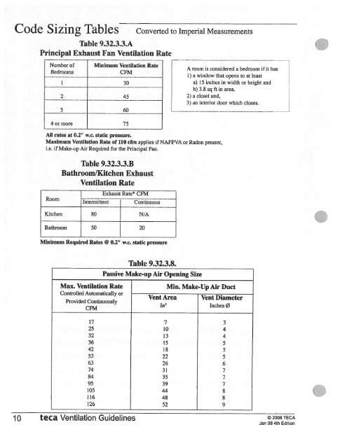
Code <strong>Sizing</strong> <strong>Tables</strong><br />
Table 9.32.3.3.A<br />
Principal Exhaust Fan <strong>Ventilation</strong> Rate<br />
Converted to Imperial Measurements<br />
Number of Minimum <strong>Ventilation</strong> Rate .<br />
A room is considered a bedroom II it has<br />
Bedrooms<br />
CFM<br />
1) a window that opens to at least<br />
30 a) 15 inches in width or height and<br />
b) 3.8 sq ft in area.<br />
2) a closet and,<br />
3) an interior door which closes.<br />
3 60<br />
4or more 75<br />
All rates at 0.2” w.c. static pressure.<br />
Maximum <strong>Ventilation</strong> Rate of 110 cfin applies if NAFFVA or Radon present,<br />
i.e. if Make-up Air Required for the Principal Fan.<br />
Table 9.32.3.3.B<br />
Bathroom/Kitchen Exhaust<br />
<strong>Ventilation</strong> Rate<br />
1 Exhaust Rate CFM<br />
Room<br />
I Intermittent Continuous<br />
1<br />
Kitchen 80 N/A<br />
.<br />
L00mJ__<br />
Minimum Required Rates @ 0.2” w.c. static pressure<br />
Max. <strong>Ventilation</strong> Rate<br />
Controlled Automatically or<br />
Provided Continuously<br />
CFM<br />
Table 9.32.3.8.<br />
Passive Make-up Air Opening Size<br />
Vent Area<br />
In2<br />
Mm. Make-Up Air Duct<br />
Vent Diameter<br />
Inches 0<br />
10<br />
teca<br />
17 7 3<br />
25 10 4<br />
32 13 4<br />
36 15 5<br />
42 18 5<br />
53 —-<br />
2) 5<br />
63 26 6<br />
74 31 7<br />
84 35 7<br />
95 39 7<br />
105 44 8<br />
116 48 8<br />
126 52 9<br />
<strong>Ventilation</strong> Guidelines<br />
© 2008 TECA<br />
Jan 08 4th Edition
capacity. This problem is noted on Checklists with the ftllowing footnote: For fan capacities exceeding Table<br />
Some fan manufacturer’s provide complete installation instructions with their equipment including<br />
• Following manufacturer’s instructions is the preferred way to size ducts for larger fans.<br />
Contractors need a reference to size duct for both exhaust and make-up air fans which exceed this rather low cfrn<br />
9.32.3.9, follow manufacturer’s installation instructions or use good engineering practice to size duct.”<br />
Code Table 9.323.9. (used to size ducts for exhaust fans) shows a maximum [an rating of only 147 cfm.<br />
Jr 08 5th Edit’on<br />
See Examp C, pg 33-A, Step 10 forcaIcLatioft<br />
--<br />
24-A teca <strong>Ventilation</strong> GuideHnes<br />
© 2008 TECA<br />
54°F— (—10°F) = 64°F 34°F —_(—6°F) = 40°F<br />
Remember when subtracting negative numbers: two negatives make a positive!<br />
Duct 1-leater (kw)<br />
= 1.1 x(54°F—°F WmterDesignfempyourlocatton)<br />
3) Make-up air delivered directly to occupied area and tempered to 54°F:<br />
3413 BTUH/kw<br />
2) Make-up air previously tempered to 34°F , delivered to occupied area through a transfer grille and<br />
Duct Heater (kw) =<br />
further tempered to 54°F: See Example B, pg 29-A,<br />
(Make-up Fan cfm) x 1 .1 x (54° F —<br />
801-1100 140 J<br />
291—380 80<br />
381—430 90<br />
561—700 110<br />
701—800 120<br />
1) the type of duct and its installed length<br />
34°<br />
F)<br />
Step 8 for calculations.<br />
3413 BTUHIkw<br />
Duct Heater (kw) =<br />
1) Make-up air delivered to unoccupied areas and tempered to 34°F:<br />
PRocEDuRE: Use Design Temp Chart (pg 20) to find °F winter design temperatures for BC location.<br />
Use the following formulae to calculate duct heater sizes depending on application:<br />
• make-up air delivered to unoccupied areas must be tempered to 34°F (1°C) in ll BC locations.<br />
• make-up air delivered to occupied areas must be tempered to 54°F (12°C) in iii! BC locations.<br />
The 2006 Code has two tempering requirements for active make-up air fans:<br />
Duct Heater <strong>Sizing</strong><br />
3) all fittings—including elbows, grills, and<br />
148—290 7”ø<br />
up air system components including:<br />
velocities of 1000 to 1100 fpm—well within the<br />
good practice recommendations.<br />
When selecting a make-up air fan, remember to<br />
account for all static pressure losses from make<br />
outskle exhaust hood.<br />
This means transfer grilles will seldom be used as they require two temperings, the second of which is not<br />
particularly practical to achieve.<br />
is 1200 fpm. This chart is based on maximum<br />
CFM Range Smooth Duct Size<br />
--<br />
velocity in main ducts (for proper fan operation)<br />
DUCT SIZING CHART The good practice maximum recomniended duct<br />
2) installed duct heater for air tempering<br />
LARGE MAKE-up ATR/ExFIAusTF DESIGN CONSIDERATIONS:<br />
• If the fans you purchase do not have duct sizing tables in the manufacturer’s literature, use the table<br />
duct sizing charts. (Dacor and Thermador are examples of manufacturer’s who supply such charts.)<br />
Check with your supplier regarding literature available for fans they stock.<br />
below for sizing smooth duct. If using flex duct, go one size larger.<br />
Duct <strong>Sizing</strong> for Larger Fans Good Practice Guidelines<br />
Appendix<br />
.<br />
.