Download - Westek
Download - Westek
Download - Westek

Create successful ePaper yourself
Turn your PDF publications into a flip-book with our unique Google optimized e-Paper software.
Considerations When Specifying a<br />
DC Power Supply<br />
Volts<br />
0.75%<br />
+/- 2%<br />
T r<br />
< 1ms<br />
Current<br />
Pre-load<br />
DUT<br />
Time<br />
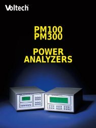
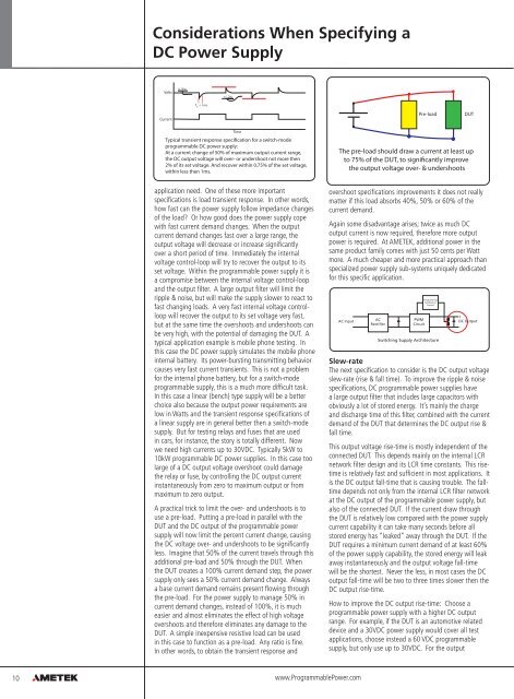
Typical transient response specification for a switch-mode<br />
programmable DC power supply:<br />
At a current change of 50% of maximum output current range,<br />
the DC output voltage will over- or undershoot not more then<br />
2% of its set voltage. And recover within 0.75% of the set voltage,<br />
within less then 1ms.<br />
The pre-load should draw a current at least up<br />
to 75% of the DUT, to significantly improve<br />
the output voltage over- & undershoots<br />
application need. One of these more important<br />
specifications is load transient response. In other words,<br />
how fast can the power supply follow impedance changes<br />
of the load? Or how good does the power supply cope<br />
with fast current demand changes. When the output<br />
current demand changes fast over a large range, the<br />
output voltage will decrease or increase significantly<br />
over a short period of time. Immediately the internal<br />
voltage control-loop will try to recover the output to its<br />
set voltage. Within the programmable power supply it is<br />
a compromise between the internal voltage control-loop<br />
and the output filter. A large output filter will limit the<br />
ripple & noise, but will make the supply slower to react to<br />
fast changing loads. A very fast internal voltage controlloop<br />
will recover the output to its set voltage very fast,<br />
but at the same time the overshoots and undershoots can<br />
be very high, with the potential of damaging the DUT. A<br />
typical application example is mobile phone testing. In<br />
this case the DC power supply simulates the mobile phone<br />
internal battery. Its power-bursting transmitting behavior<br />
causes very fast current transients. This is not a problem<br />
for the internal phone battery, but for a switch-mode<br />
programmable supply, this is a much more difficult task.<br />
In this case a linear (bench) type supply will be a better<br />
choice also because the output power requirements are<br />
low in Watts and the transient response specifications of<br />
a linear supply are in general better then a switch-mode<br />
supply. But for testing relays and fuses that are used<br />
in cars, for instance, the story is totally different. Now<br />
we need high currents up to 30VDC. Typically 5kW to<br />
10kW programmable DC power supplies. In this case too<br />
large of a DC output voltage overshoot could damage<br />
the relay or fuse, by controlling the DC output current<br />
instantaneously from zero to maximum output or from<br />
maximum to zero output.<br />
A practical trick to limit the over- and undershoots is to<br />
use a pre-load. Putting a pre-load in parallel with the<br />
DUT and the DC output of the programmable power<br />
supply will now limit the percent current change, causing<br />
the DC voltage over- and undershoots to be significantly<br />
less. Imagine that 50% of the current travels through this<br />
additional pre-load and 50% through the DUT. When<br />
the DUT creates a 100% current demand step, the power<br />
supply only sees a 50% current demand change. Always<br />
a base current demand remains present flowing through<br />
the pre-load. For the power supply to manage 50% in<br />
current demand changes, instead of 100%, it is much<br />
easier and almost eliminates the effect of high voltage<br />
overshoots and therefore eliminates any damage to the<br />
DUT. A simple inexpensive resistive load can be used<br />
in this case to function as a pre-load. Any ratio is fine.<br />
In other words, to obtain the transient response and<br />
overshoot specifications improvements it does not really<br />
matter if this load absorbs 40%, 50% or 60% of the<br />
current demand.<br />
Again some disadvantage arises; twice as much DC<br />
output current is now required, therefore more output<br />
power is required. At AMETEK, additional power in the<br />
same product family comes with just 50 cents per Watt<br />
more. A much cheaper and more practical approach than<br />
specialized power supply sub-systems uniquely dedicated<br />
for this specific application.<br />
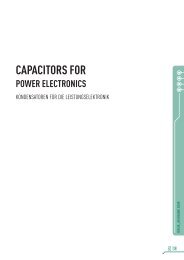
AC Input<br />
AC<br />
Rectifier<br />
PWM<br />
Circuit<br />
Programming<br />
Feedback &<br />
Control<br />
Switching Supply Architecture<br />
+<br />
DC Output<br />
-<br />
Slew-rate<br />
The next specification to consider is the DC output voltage<br />
slew-rate (rise & fall time). To improve the ripple & noise<br />
specifications, DC programmable power supplies have<br />
a large output filter that includes large capacitors with<br />
obviously a lot of stored energy. It’s mainly the charge<br />
and discharge time of this filter, combined with the current<br />
demand of the DUT that determines the DC output rise &<br />
fall time.<br />
This output voltage rise-time is mostly independent of the<br />
connected DUT. This depends mainly on the internal LCR<br />
network filter design and its LCR time constants. This risetime<br />
is relatively fast and sufficient in most applications. It<br />
is the DC output fall-time that is causing trouble. The falltime<br />
depends not only from the internal LCR filter network<br />
at the DC output of the programmable power supply, but<br />
also of the connected DUT. If the current draw through<br />
the DUT is relatively low compared with the power supply<br />
current capability it can take many seconds before all<br />
stored energy has “leaked” away through the DUT. If the<br />
DUT requires a minimum current demand of at least 60%<br />
of the power supply capability, the stored energy will leak<br />
away instantaneously and the output voltage fall-time<br />
will be the shortest. Never the less, in most cases the DC<br />
output fall-time will be two to three times slower then the<br />
DC output rise-time.<br />
How to improve the DC output rise-time: Choose a<br />
programmable power supply with a higher DC output<br />
range. For example, if the DUT is an automotive related<br />
device and a 30VDC power supply would cover all test<br />
applications, choose instead a 60 VDC programmable<br />
supply, but only use up to 30VDC. For the output<br />
10<br />
www.ProgrammablePower.com