Download - Westek
Download - Westek
Download - Westek

Create successful ePaper yourself
Turn your PDF publications into a flip-book with our unique Google optimized e-Paper software.
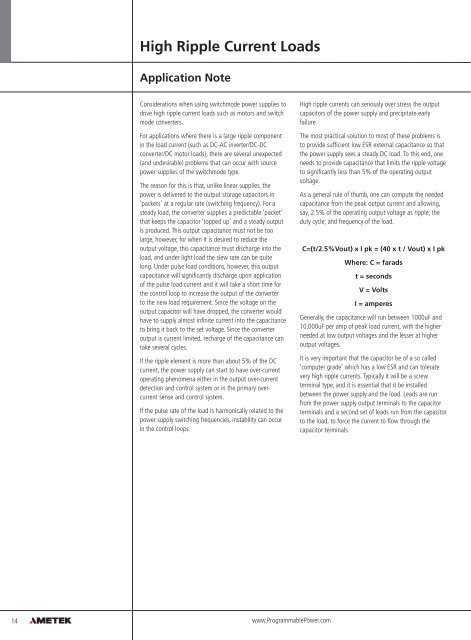
High Ripple Current Loads<br />
Application Note<br />
Considerations when using switchmode power supplies to<br />
drive high ripple current loads such as motors and switch<br />
mode converters.<br />
For applications where there is a large ripple component<br />
in the load current (such as DC-AC inverter/DC-DC<br />
converter/DC motor loads), there are several unexpected<br />
(and undesirable) problems that can occur with source<br />
power supplies of the switchmode type.<br />
The reason for this is that, unlike linear supplies, the<br />
power is delivered to the output storage capacitors in<br />
‘packets’ at a regular rate (switching frequency). For a<br />
steady load, the converter supplies a predictable ‘packet’<br />
that keeps the capacitor ‘topped up’ and a steady output<br />
is produced. This output capacitance must not be too<br />
large, however, for when it is desired to reduce the<br />
output voltage, this capacitance must discharge into the<br />
load, and under light load the slew rate can be quite<br />
long. Under pulse load conditions, however, this output<br />
capacitance will significantly discharge upon application<br />
of the pulse load current and it will take a short time for<br />
the control loop to increase the output of the converter<br />
to the new load requirement. Since the voltage on the<br />
output capacitor will have dropped, the converter would<br />
have to supply almost infinite current into the capacitance<br />
to bring it back to the set voltage. Since the converter<br />
output is current limited, recharge of the capacitance can<br />
take several cycles.<br />
If the ripple element is more than about 5% of the DC<br />
current, the power supply can start to have over-current<br />
operating phenomena either in the output over-current<br />
detection and control system or in the primary overcurrent<br />
sense and control system.<br />
If the pulse rate of the load is harmonically related to the<br />
power supply switching frequencies, instability can occur<br />
in the control loops.<br />
High ripple currents can seriously over stress the output<br />
capacitors of the power supply and precipitate early<br />
failure.<br />
The most practical solution to most of these problems is<br />
to provide sufficient low ESR external capacitance so that<br />
the power supply sees a steady DC load. To this end, one<br />
needs to provide capacitance that limits the ripple voltage<br />
to significantly less than 5% of the operating output<br />
voltage.<br />
As a general rule of thumb, one can compute the needed<br />
capacitance from the peak output current and allowing,<br />
say, 2.5% of the operating output voltage as ripple; the<br />
duty cycle; and frequency of the load.<br />
C=(t/2.5%Vout) x I pk = (40 x t / Vout) x I pk<br />
Where: C = farads<br />
t = seconds<br />
V = Volts<br />
I = amperes<br />
Generally, the capacitance will run between 1000uF and<br />
10,000uF per amp of peak load current, with the higher<br />
needed at low output voltages and the lesser at higher<br />
output voltages.<br />
It is very important that the capacitor be of a so called<br />
‘computer grade’ which has a low ESR and can tolerate<br />
very high ripple currents. Typically it will be a screw<br />
terminal type, and it is essential that it be installed<br />
between the power supply and the load. Leads are run<br />
from the power supply output terminals to the capacitor<br />
terminals and a second set of leads run from the capacitor<br />
to the load, to force the current to flow through the<br />
capacitor terminals.<br />
14<br />
www.ProgrammablePower.com