Download - Westek
Download - Westek
Download - Westek

You also want an ePaper? Increase the reach of your titles
YUMPU automatically turns print PDFs into web optimized ePapers that Google loves.
Advanced Electronic Power Simulation<br />
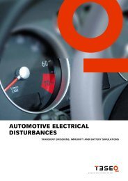
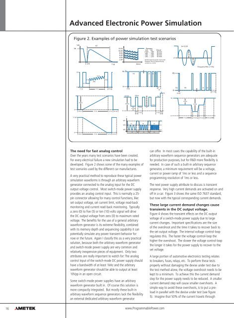
Figure 2. Examples of power simulation test scenarios<br />
Vb<br />
Vdc<br />
t6<br />
td<br />
T (s)<br />
13.5V Rampen<br />
10.0V<br />
von bis Dauer<br />
+10V ... +8V 10 min<br />
8.0V<br />
6.0V<br />
4.0V<br />
+4V ... +2V<br />
+8V ... +6V<br />
+6V ... +4V<br />
10 min<br />
10 min<br />
10 min<br />
2.0V<br />
Batteriespannung Ub nach jeder<br />
Rampen ohne Unterbrechung<br />
zurück zu +13.5V.<br />
10min<br />
+7.5V<br />
U=13.5V<br />
1V<br />
1V<br />
Frequenz 4Hz +/-1Hz<br />
12V<br />
1s<br />
Vb<br />
10t 3t 2t t<br />
Vb<br />
Vp [V]<br />
VI [V]<br />
V2 [V]<br />
[Hz]<br />
V3 [V]<br />
0<br />
t1 [s]<br />
t2 [s]<br />
t3 [s]<br />
0<br />
t<br />
[rns]<br />
t1<br />
[s]<br />
10s<br />
0<br />
t<br />
[rns]<br />
10t 3t 2t t<br />
t1 [s]<br />
9V/18V<br />
250ms<br />
5s<br />
Vb<br />
0<br />
V2[V]<br />
t0 [s] t1 [s] t2 [s] Int [s]<br />
0<br />
Vh [V]<br />
750ms<br />
VI [V]<br />
th<br />
tI [s]<br />
[s]<br />
5/10V<br />
t1 [s]<br />
t2<br />
[s]<br />
2s Vb<br />
t1 [s] t2 [s]<br />
VI [V]<br />
VI [V]<br />
V1[V]<br />
v<br />
0<br />
t3 [s]<br />
Int [s]<br />
VB1<br />
VB3<br />
f1 f2 fn<br />
0<br />
t0 [s] t1 [s] t2 [s] Int [s]<br />
VB2<br />
t1 t2 t1 t2 t1<br />
t<br />
The need for fast analog control<br />
Over the years many test scenarios have been created.<br />
For every electrical failure a new simulation had to be<br />
developed. Figure 2 shows some of the many examples of<br />
test scenarios used by the different car manufactures.<br />
A very practical method to reproduce these typical power<br />
simulation waveforms is through an arbitrary waveform<br />
generator connected to the analog input for the DC<br />
output voltage control. Most switch-mode power supply<br />
provides an analog control input. This is normally a 25-<br />
pin connector allowing for many control functions, like:<br />
set output voltage, set current limit, voltage read-back<br />
monitoring and current read-back monitoring. Typically<br />
a zero (0) to five (5) or ten (10) volts signal will drive<br />
the DC output voltage from zero (0) to maximum rated<br />
voltage. The benefits for the use of a general arbitrary<br />
waveform generator is its extreme flexibility, combined<br />
with its memory depth and sequencing capability it can<br />
potentially simulate any power transient behavior for<br />
now or the future. Again I classify this as a very practical<br />
solution, because both the arbitrary waveform generator<br />
and switch-mode power supply are very common and<br />
relatively inexpensive pieces of equipment. Only two<br />
attributes are really important to watch for: The analog<br />
control input of the switch-mode DC power supply should<br />
have a bandwidth of at least 1kHz and the arbitrary<br />
waveform generator should be able to output at least<br />
10Vpp in an open circuit.<br />
Some switch-mode power supplies have an arbitrary<br />
waveform generator built in. Of course this solution is<br />
more compactly integrated. But mostly these built-in<br />
arbitrary waveform sequence generators lack the flexibility<br />
an external dedicated arbitrary waveform generator<br />
can offer. In most cases the capability of the built-in<br />
arbitrary waveform sequence generators are adequate<br />
for production purposes, but for R&D more flexibility is<br />
needed. In case of such a built-in arbitrary sequence<br />
generator, a minimum requirement will be a voltage,<br />
current or power ramp of 1ms or less and a sequence<br />
programming resolution of 1ms or less.<br />
The next power supply attribute to discuss is transient<br />
response. Very high current demands are activated on and<br />
off in a car. Figure 3 shows the same ISO 7637 standard,<br />
but now with the typical corresponding current demands.<br />
These large current demand changes cause<br />
transients in the DC output voltage.<br />
Figure 4 shows the transient effects on the DC output<br />
voltage of a switch-mode power supply due to large<br />
current changes. Important specifications are the size<br />
of the overshoot and the time it takes to recover back to<br />
the set output voltage. The internal voltage control-loop<br />
regulates this. The faster the voltage control-loop the<br />
higher the overshoot. The slower the voltage control-loop<br />
the longer it takes for the power supply to recover to the<br />
set voltage.<br />
A large portion of automotive electronics testing relates<br />
to breakers, fuses, relays, etc. To perform these tests<br />
properly without damaging the devise under test due to<br />
the test method alone, the voltage overshoot needs to be<br />
kept to a minimum. To achieve this the current demand<br />
step for the power supply needs to be reduced. A smaller<br />
current demand step will cause smaller overshoots. A<br />
simple way to avoid these overshoots, is to put a preload<br />
in parallel with the devise under test (see figure<br />
5). Imagine that 50% of the current travels through<br />
16<br />
www.ProgrammablePower.com