FILLING AND CHECK VALVE
FILLING AND CHECK VALVE
FILLING AND CHECK VALVE

You also want an ePaper? Increase the reach of your titles
YUMPU automatically turns print PDFs into web optimized ePapers that Google loves.
<strong>FILLING</strong> <strong>AND</strong> <strong>CHECK</strong> <strong>VALVE</strong><br />
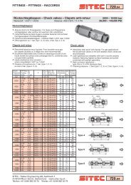
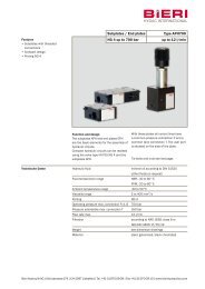
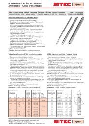
Filling valves characteristics<br />
TYPE<br />
Size<br />
Max.<br />
Flow<br />
Max.<br />
Press.<br />
Opening<br />
ratio<br />
Decompr.<br />
ratio<br />
Max pilot<br />
pressure<br />
Opening<br />
pressure<br />
Weight<br />
(Kg)<br />
R-114 DN-32 160 l/min. 3.6:1 1.2<br />
R-112 DN-40 250 l/min. 3.9:1 0.12 bar 1.7<br />
R-200 DN-50 400 l/min.<br />
2.5<br />
4.2:1<br />
R-212 DN-63 600 l/min.<br />
3.5<br />
400 bar<br />
R-300 DN-80 1000 l/min. 4.5:1 1:5 100 bar<br />
5.2<br />
0.13 bar<br />
R-400 DN-100 1600 l/min. 12<br />
R-500 DN-125 2500 l/min.<br />
4.3:1<br />
20<br />
R-600 DN-160 4000 l/min.<br />
42<br />
0.15 bar<br />
R-800 DN-200 7000 l/min. 350 bar 4.0:1<br />
116<br />
Description<br />
These valves allow the quick pre-filling and<br />
discharging of cylinders in compression presses.<br />
They are available with or without pre-opening<br />
device.<br />
The conical seat of the obturator allows the perfect<br />
sealing.<br />
PP Pilot port<br />
P Auxiliary pressure<br />
port<br />
IN Tank side<br />
OUT Cylinder side<br />
Check valves characteristics<br />
TYPE Size Max. flow<br />
Max.<br />
Pressure<br />
Opening<br />
pressure<br />
Weight<br />
(Kg)<br />
RR-114 DN-32 160 l/min. 1<br />
RR-112 DN-40 250 l/min. 0.12 bar<br />
1.5<br />
RR-200 DN-50 400 l/min.<br />
2<br />
RR-212 DN-63 600 l/min. 3<br />
400 bar<br />
RR-300 DN-80 1000 l/min. 4.5<br />
0.13 bar<br />
RR-400 DN-100 1600 l/min. 10<br />
RR-500 DN-125 2500 l/min.<br />
16<br />
RR-600 DN-160 4000 l/min.<br />
33.5<br />
0.15 bar<br />
RR-800 DN-200 7000 l/min. 350 bar<br />
Description<br />
The check valves allow the flow in one direction<br />
and prevent it in the opposite one.<br />
The mounting is in line by means of suitable<br />
flanges according to DIN norms.<br />
IN Tank side<br />
OUT Cylinder side<br />
1/6 F01 01/10
<strong>FILLING</strong> <strong>AND</strong> <strong>CHECK</strong> <strong>VALVE</strong><br />
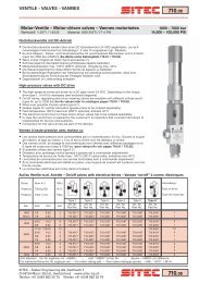
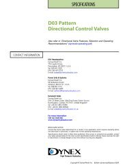
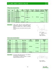
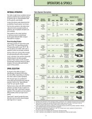
<strong>FILLING</strong> <strong>VALVE</strong>S<br />
POS<br />
DENOMINATION<br />
1 BODY ( steel)<br />
2 PILOT PISTON BODY<br />
3 OBTURATOR<br />
4 PISTON PILOT<br />
5 SPRING LOCKING CAP<br />
6 OBTURATOR RETURN SPRING<br />
7 PILOT PISTON RETURN SPRING<br />
8 LOCKING RING<br />
9 BRAKING GRUB SCREW<br />
10 SEAL (see table)<br />
11 SEAL<br />
12 SCREWS<br />
TYPE A B C D E F G H I P (Bsp)<br />
R-114 93 43 43 32 55 27 8.2 32 60° 1/4<br />
R-112 108 58 58 39 60 28 8.9 41.5 45° 1/4<br />
R-200 128 73 73 45 72 29 12.9 53 45° 1/4<br />
R-212 143 87 87 50 83 34 13.4 63 45° 1/4<br />
R-300 169 107 107 56 98 38.5 17.8 80 45° 1/4<br />
R-400 212 130 130 70 118 44 23.4 100 45° 3/8<br />
R-500 248 168 151 88 154 51 27.4 127 - 3/8<br />
R-600 310 215 215 108 220 70 38.9 160 - -<br />
R-800 420 310 260 140 300 120 40.4 200 - -<br />
2/6 F01 01/10
<strong>FILLING</strong> <strong>AND</strong> <strong>CHECK</strong> <strong>VALVE</strong><br />
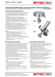
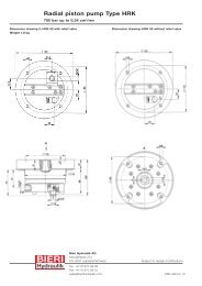
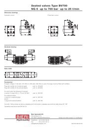
<strong>CHECK</strong> <strong>VALVE</strong><br />
POS<br />
DENOMINATION<br />
1 BODY ( steel)<br />
2 OBTURATOR<br />
3 SPRING LOCKING CAP<br />
4 OBTURATOR RETURN SPRING<br />
5 LOCKING RING<br />
6 BRAKING GRUB SCREW<br />
7 SEAL (see table)<br />
8 ¼ “ BSP PLUG<br />
TYPE A B C F G H<br />
RR-114 93 43 43 27 8.2 32<br />
RR-112 108 58 58 28 8.9 41.5<br />
RR-200 128 73 73 29 12.9 53<br />
RR-212 143 87 87 34 13.4 63<br />
RR-300 169 107 107 38.5 17.8 88<br />
RR-400 212 130 130 44 23.4 100<br />
RR-500 248 168 151 51 27.4 127<br />
RR-600 310 215 215 70 38.9 160<br />
RR-800 420 310 260 120 40.4 200<br />
3/6 F01 01/10
<strong>FILLING</strong> <strong>AND</strong> <strong>CHECK</strong> <strong>VALVE</strong><br />
Flanges dimensions<br />
TYPE UNI DIN DN a b c d e f g h<br />
FL-R114 2284 2635 40 43.5 88 110 150 43 18 2.5 15<br />
FL-R112 2285 2636 50 54.5 95 135 180 62 22 2.5 23<br />
FL-R200 2285 2636 65 70 120 160 205 68 22 2.5 23<br />
FL-R212 2285 2636 80 83 130 170 215 72 22 2.5 25<br />
FL-R300 2285 2636 100 107.5 160 200 250 78 25 2.5 27<br />
FL-R400 2286 2637 125 127.4 185 250 315 105 33 2.5 37<br />
FL-R500 2286 2637 150 147 215 290 355 115 33 3 41<br />
LOCKING TORQUE<br />
TYPE A Screw N°of screws ø d ø D h<br />
(kgm)<br />
R-114/FL 117 M16 x 80 - - - 21<br />
4<br />
R-112/FL 152 M20 x 110<br />
27 27.5 30<br />
R-200/FL 165 M20 x 110 20.5 34 28.5 38<br />
R-212/FL 178 M20 x 120<br />
29 34 41<br />
8<br />
R-300/FL 195 M24x 130 24.5 32 38 70<br />
R-400/FL 254 M30 x 160<br />
38 43.5 110<br />
30.5<br />
R-500/FL 281 M30 x 160 12<br />
41.5 56 130<br />
4/6 F01 01/10
<strong>FILLING</strong> <strong>AND</strong> <strong>CHECK</strong> <strong>VALVE</strong><br />
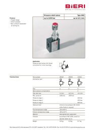
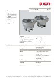
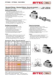
Differential pressure in suction and filling in relation to the flow<br />
Nominal sizes 32, 40, 50<br />
0,4<br />
R-114(DN-32)<br />
R-112(DN-40)<br />
R-200(DN-50)<br />
Pressure differential (bar)<br />
0,3<br />
0,2<br />
0,1<br />
0<br />
0 100 200 300 400 500<br />
Flow (L/min)<br />
0,4<br />
Nominal sizes 63, 80, 100<br />
R212(DN-63)<br />
R-300(DN-80)<br />
R-400(DN-100)<br />
Pressure differential (bar)<br />
0,3<br />
0,2<br />
0,1<br />
0<br />
0 200 400 600 800 1000 1200 1400 1600 1800 2000<br />
Flow (L/min)<br />
0,4<br />
Nominal sizes 125, 160, 200<br />
R-500(DN-125)<br />
R-600(DN-160)<br />
R-800(DN-200)<br />
Pressure differential (bar)<br />
0,3<br />
0,2<br />
0,1<br />
0<br />
0 1000 2000 3000 4000 5000 6000 7000<br />
Flow (L/min)<br />
5/6 F01 01/10
<strong>FILLING</strong> <strong>AND</strong> <strong>CHECK</strong> <strong>VALVE</strong><br />
Seal<br />
SEAL x R***<br />
Model (copper-made ) O-Rings (90Shore) Square Ring SR- 400<br />
R-114 R52x45x2<br />
R-112 R68x60x2<br />
R-200 R85x75,5x2<br />
R-212 OR-6375 (2-343)<br />
R-300 OR-6450 (2-349)<br />
R-400 OR-8550 (2-433)<br />
R-500 7-442<br />
R-600 7-447<br />
R-800 7-455<br />
Installation rules<br />
• For sizes up to 212, the assembly can be made either vertical or horizontal. For bigger sizes the horizontal<br />
assembly is compulsory.<br />
• Fluid to be used: hydraulic oil in compliance with DIN 51524 rules, viscosity between 30 and 100 mm 2 /s (cSt)<br />
at 40°C<br />
• Recommended filtration of 25µ.<br />
• Hydraulic fluid temperature: from -20° to +75°C<br />
Ordering code<br />
** - *** / PA - FL<br />
Equipped with 2 flanges (on request)<br />
Equipped with pre-opening device (on request, only for sizes from 114 to 400)<br />
Size 114 + 800<br />
R = Quick filling and discharging valve RR = Check valve<br />
6/6 F01 01/10