Installation and Wiring Instructions - Sargent and Greenleaf
Installation and Wiring Instructions - Sargent and Greenleaf
Installation and Wiring Instructions - Sargent and Greenleaf

Create successful ePaper yourself
Turn your PDF publications into a flip-book with our unique Google optimized e-Paper software.
<strong>Sargent</strong> & <strong>Greenleaf</strong>, Inc.<br />
Model 6102-090 Duress Module <strong>and</strong><br />
Model 6102-100 Remote Enable with Duress<br />
Module for 6124, 6125, 6126, 6127, 6128, 6129, Titan 2006, <strong>and</strong> Titan 2007 Electronic Locks<br />
Mounting Considerations<br />
<strong>Installation</strong> <strong>and</strong> Operating <strong>Instructions</strong><br />
• The module is mounted with one screw per Figure 7.<br />
• The duress (silent alarm) feature of the modules can be used with the S&G 6124, 6125, 6126, 6127,<br />
6128, 6129, <strong>and</strong> Titan (models 2006, 2007) series electronic locks.<br />
• The remote enable feature of the 6102-100 module can be used with S&G electronic locks in the<br />
6120, 6123, 6124, 6125, 6126, 6127, 6128, 6129, Z 02 (models 2002, 2004) <strong>and</strong> Titan (models 2006,<br />
2007) series.<br />
• Both modules can readily be added to new or existing installations.<br />
• Unless the module is installed within 10” (25 cm) of the lock, S&G lock extension cables will be<br />
required.<br />
• Care must be taken to protect wiring from being damaged or broken during installation <strong>and</strong> when the<br />
safe is in service. Avoid routing the wires near moving parts of the safe <strong>and</strong> boltwork. Use wire tie<br />
devices to secure all wires that must be routed near moving parts.<br />
• The modules have very low power consumption <strong>and</strong> are powered by the 9V alkaline battery (or<br />
batteries) in the keypad with very little effect on battery life.<br />
<strong>Installation</strong> . . .<br />
Step 1<br />
Locate a smooth flat area on the inside of the safe door<br />
to mount the module. It should be located within 10” (25<br />
cm) of the lock. Drill <strong>and</strong> tap (1) - #8-32 (or M4) hole for<br />
mounting per the “Outline” drawing, Figure 7. The<br />
orientation of the module does not affect operation.<br />
Step 2<br />
Figure 1<br />
Clean the mounting surface for the module with alcohol if<br />
any dirt or oil is on the safe door. Remove the paper<br />
cover from the adhesive strips on the bottom of the module. Position the module base over the<br />
mounting hole <strong>and</strong> press firmly in place.<br />
Step 3<br />
Position the module cover over the base <strong>and</strong> mount with screw provided - (1) #8-32 (silver<br />
colored) or (1) M4 (red colored).<br />
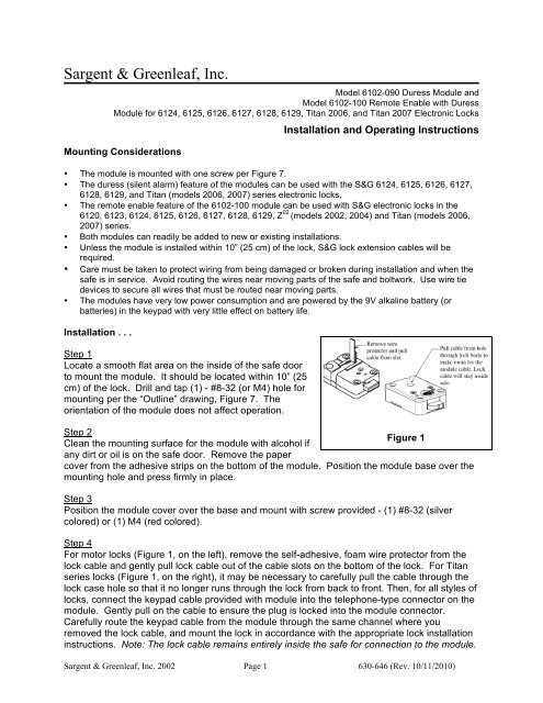
Step 4<br />
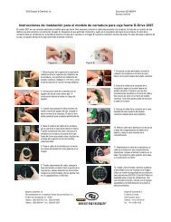
For motor locks (Figure 1, on the left), remove the self-adhesive, foam wire protector from the<br />
lock cable <strong>and</strong> gently pull lock cable out of the cable slots on the bottom of the lock. For Titan<br />
series locks (Figure 1, on the right), it may be necessary to carefully pull the cable through the<br />
lock case hole so that it no longer runs through the lock from back to front. Then, for all styles of<br />
locks, connect the keypad cable provided with module into the telephone-type connector on the<br />
module. Gently pull on the cable to ensure the plug is locked into the module connector.<br />
Carefully route the keypad cable from the module through the same channel where you<br />
removed the lock cable, <strong>and</strong> mount the lock in accordance with the appropriate lock installation<br />
instructions. Note: The lock cable remains entirely inside the safe for connection to the module.<br />
<strong>Sargent</strong> & <strong>Greenleaf</strong>, Inc. 2002 Page 1 630-646 (Rev. 10/11/2010)
Model 6102-090 Duress Module <strong>and</strong><br />
Model 6102-100 Remote Enable with Duress<br />
Module <strong>Installation</strong> <strong>and</strong> Operating <strong>Instructions</strong><br />
Step 5<br />
Plug the lock cable into the module 4-pin connector <strong>and</strong> use one of the wire ties to secure the<br />
lock cable to the wire tie mount provided (see Figure 3 to locate wire tie mount on safe panel).<br />
Step 6<br />
Complete the installation of the lock keypad in accordance<br />
with the lock installation instructions.<br />
Step 7<br />
Verify proper operation of the lock/module installation a<br />
minimum of three times prior to closing the safe door.<br />
Note: On the 6102-100 Remote Enable with Duress<br />
module (Figures 2 <strong>and</strong> 5), if the Enable/Disable switch<br />
is in the “Enable” position, the lock will not operate<br />
unless the remote voltage signal is applied to terminals<br />
4 <strong>and</strong> 5.<br />
6102-100<br />
Remote Enable with Duress<br />
Module<br />
Figure 2<br />
Note for Special 6102-C Module:<br />
The special module marked “6102-C” on its label has an internal battery lead for connection of a 9V battery to power<br />
the lock <strong>and</strong> module. When this internal battery option is used, no batteries are required in the keypad to operate the<br />
lock <strong>and</strong> module. However, a battery can be installed in the keypad to open the lock if the internal battery is too low to<br />
open the lock.<br />
<strong>Wiring</strong> Guidelines . . .<br />
For external wiring to module terminal block:<br />
• For strain relief, route wires to utilize wire tie points<br />
indicated in Figure 3.<br />
• Wire size range for wiring terminals: 16 to 30 AWG<br />
(solid or str<strong>and</strong>ed wire)<br />
• Suggested wire strip length is .20” (5 mm).<br />
• Maximum terminal screw torque is 5 in-lb (0.5 Nm).<br />
• The normally open <strong>and</strong> normally closed Duress<br />
(silent alarm) contact connections are indicated on<br />
the module label.<br />
• For the 6102-100 ‘E’ Remote Enable with Duress<br />
module, the remote signal connections are indicated<br />
on the module label.<br />
6102-090 Duress Module<br />
Figure 3<br />
<strong>Sargent</strong> & <strong>Greenleaf</strong>, Inc. 2002 Page 2 630-646 (Rev. 10/11/2010)
Model 6102-090 Duress Module <strong>and</strong><br />
Model 6102-100 Remote Enable with Duress<br />
Module <strong>Installation</strong> <strong>and</strong> Operating <strong>Instructions</strong><br />
Connection Diagram . . .<br />
5 – 12Vdc (6mA typical)<br />
Enable/Disable Signal<br />
Silent Alarm Contacts<br />
(activated for 2 seconds)<br />
Silent Alarm Contacts (activated for 2 seconds)<br />
6102-100 Duress with<br />
Remote Enable/Disable Module<br />
Figure 4<br />
6102-090 Duress (only) Module<br />
Figure 5<br />
Module Operation . . .<br />
After installation of the Duress (6102-090) or Remote Enable with Duress (6102-100) module,<br />
the lock must be programmed to enable the Duress function (see lock programming instruction<br />
document). The lock should only be programmed for duress function if connected to an<br />
active, monitored central alarm system via the duress module.<br />
The remote enable feature of the Remote Enable with Duress module comes from the factory in<br />
the remote disable mode, (i.e. the lock will operate until a disable voltage signal is applied to<br />
module terminals 4 <strong>and</strong> 5). The module may be changed to the<br />
remote enable function, (i.e. the lock will not operate until an<br />
enable voltage signal is applied to module terminals 4 <strong>and</strong> 5), by<br />
changing the enable/disable switch from “Disable” to “Enable.”<br />
Step 1<br />
Remove power from the lock/module <strong>and</strong> use the tip of a ballpoint<br />
pen to push down on the Enable/Disable rocker switch to change<br />
from the factory set “Disable” to the “Enable” position as indicated<br />
on the Module label (see Figure 6).<br />
Step 2<br />
Verify proper operation of the lock/module installation a minimum<br />
of three times prior to closing the safe door. The lock must operate<br />
properly when the enable voltage signal is present on module<br />
terminals 4 <strong>and</strong> 5.<br />
Enable/Disable Switch<br />
6102-100 ‘E’ Duress with<br />
Remote Enable/Disable Module<br />
Figure 6<br />
<strong>Sargent</strong> & <strong>Greenleaf</strong>, Inc. 2002 Page 3 630-646 (Rev. 10/11/2010)
Model 6102-090 Duress Module <strong>and</strong><br />
Model 6102-100 Remote Enable with Duress<br />
Module <strong>Installation</strong> <strong>and</strong> Operating <strong>Instructions</strong><br />
Specifications . . .<br />
Duress contact operation:<br />
The duress (silent alarm) relay operation is a momentary contact change of state. One<br />
contact is normally open <strong>and</strong> one is normally closed with a common terminal provided<br />
(Form C). The relay contacts change state one second after input of a duress code into<br />
the lock <strong>and</strong> will change back to their original state after two seconds.<br />
Duress contact ratings:<br />
Contact Rating: 1A @ 24VDC (resistive)<br />
Expected Life: >>100,000 cycles at rated load<br />
Maximum Switching Voltage: 150VDC or 125VAC<br />
Minimum Switching Capability: Dry circuit<br />
Remote Enable signal requirements (for 6102-100 ‘E’):<br />
Input Signal Voltage Rating: 5VDC - 15% to 12VDC + 15%<br />
Current Requirements: 2.5mA typical @ 5VDC<br />
6mA typical @ 12VDC<br />
Figure 7 - Outline Drawing<br />
<strong>Sargent</strong> & <strong>Greenleaf</strong>, Inc. 2002 Page 4 630-646 (Rev. 10/11/2010)