Installation and Wiring Instructions - Sargent and Greenleaf
Installation and Wiring Instructions - Sargent and Greenleaf
Installation and Wiring Instructions - Sargent and Greenleaf

You also want an ePaper? Increase the reach of your titles
YUMPU automatically turns print PDFs into web optimized ePapers that Google loves.
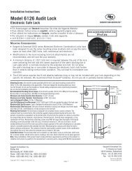
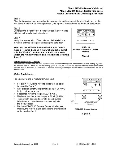
Model 6102-090 Duress Module <strong>and</strong><br />
Model 6102-100 Remote Enable with Duress<br />
Module <strong>Installation</strong> <strong>and</strong> Operating <strong>Instructions</strong><br />
Step 5<br />
Plug the lock cable into the module 4-pin connector <strong>and</strong> use one of the wire ties to secure the<br />
lock cable to the wire tie mount provided (see Figure 3 to locate wire tie mount on safe panel).<br />
Step 6<br />
Complete the installation of the lock keypad in accordance<br />
with the lock installation instructions.<br />
Step 7<br />
Verify proper operation of the lock/module installation a<br />
minimum of three times prior to closing the safe door.<br />
Note: On the 6102-100 Remote Enable with Duress<br />
module (Figures 2 <strong>and</strong> 5), if the Enable/Disable switch<br />
is in the “Enable” position, the lock will not operate<br />
unless the remote voltage signal is applied to terminals<br />
4 <strong>and</strong> 5.<br />
6102-100<br />
Remote Enable with Duress<br />
Module<br />
Figure 2<br />
Note for Special 6102-C Module:<br />
The special module marked “6102-C” on its label has an internal battery lead for connection of a 9V battery to power<br />
the lock <strong>and</strong> module. When this internal battery option is used, no batteries are required in the keypad to operate the<br />
lock <strong>and</strong> module. However, a battery can be installed in the keypad to open the lock if the internal battery is too low to<br />
open the lock.<br />
<strong>Wiring</strong> Guidelines . . .<br />
For external wiring to module terminal block:<br />
• For strain relief, route wires to utilize wire tie points<br />
indicated in Figure 3.<br />
• Wire size range for wiring terminals: 16 to 30 AWG<br />
(solid or str<strong>and</strong>ed wire)<br />
• Suggested wire strip length is .20” (5 mm).<br />
• Maximum terminal screw torque is 5 in-lb (0.5 Nm).<br />
• The normally open <strong>and</strong> normally closed Duress<br />
(silent alarm) contact connections are indicated on<br />
the module label.<br />
• For the 6102-100 ‘E’ Remote Enable with Duress<br />
module, the remote signal connections are indicated<br />
on the module label.<br />
6102-090 Duress Module<br />
Figure 3<br />
<strong>Sargent</strong> & <strong>Greenleaf</strong>, Inc. 2002 Page 2 630-646 (Rev. 10/11/2010)