Installation and Wiring Instructions - Sargent and Greenleaf
Installation and Wiring Instructions - Sargent and Greenleaf
Installation and Wiring Instructions - Sargent and Greenleaf

Create successful ePaper yourself
Turn your PDF publications into a flip-book with our unique Google optimized e-Paper software.
Model 6102-090 Duress Module <strong>and</strong><br />
Model 6102-100 Remote Enable with Duress<br />
Module <strong>Installation</strong> <strong>and</strong> Operating <strong>Instructions</strong><br />
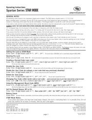
Connection Diagram . . .<br />
5 – 12Vdc (6mA typical)<br />
Enable/Disable Signal<br />
Silent Alarm Contacts<br />
(activated for 2 seconds)<br />
Silent Alarm Contacts (activated for 2 seconds)<br />
6102-100 Duress with<br />
Remote Enable/Disable Module<br />
Figure 4<br />
6102-090 Duress (only) Module<br />
Figure 5<br />
Module Operation . . .<br />
After installation of the Duress (6102-090) or Remote Enable with Duress (6102-100) module,<br />
the lock must be programmed to enable the Duress function (see lock programming instruction<br />
document). The lock should only be programmed for duress function if connected to an<br />
active, monitored central alarm system via the duress module.<br />
The remote enable feature of the Remote Enable with Duress module comes from the factory in<br />
the remote disable mode, (i.e. the lock will operate until a disable voltage signal is applied to<br />
module terminals 4 <strong>and</strong> 5). The module may be changed to the<br />
remote enable function, (i.e. the lock will not operate until an<br />
enable voltage signal is applied to module terminals 4 <strong>and</strong> 5), by<br />
changing the enable/disable switch from “Disable” to “Enable.”<br />
Step 1<br />
Remove power from the lock/module <strong>and</strong> use the tip of a ballpoint<br />
pen to push down on the Enable/Disable rocker switch to change<br />
from the factory set “Disable” to the “Enable” position as indicated<br />
on the Module label (see Figure 6).<br />
Step 2<br />
Verify proper operation of the lock/module installation a minimum<br />
of three times prior to closing the safe door. The lock must operate<br />
properly when the enable voltage signal is present on module<br />
terminals 4 <strong>and</strong> 5.<br />
Enable/Disable Switch<br />
6102-100 ‘E’ Duress with<br />
Remote Enable/Disable Module<br />
Figure 6<br />
<strong>Sargent</strong> & <strong>Greenleaf</strong>, Inc. 2002 Page 3 630-646 (Rev. 10/11/2010)