


You also want an ePaper? Increase the reach of your titles
YUMPU automatically turns print PDFs into web optimized ePapers that Google loves.
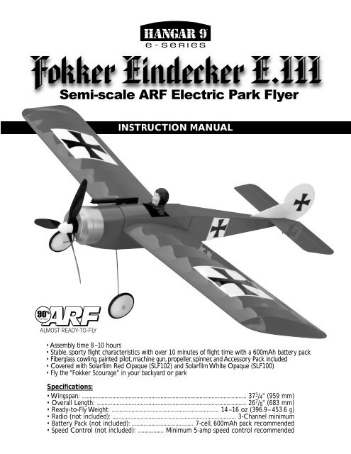
INSTRUCTION MANUAL<br />
• Assembly time 8–10 hours<br />
• Stable, sporty flight characteristics with over 10 minutes of flight time with a 600mAh battery pack<br />
• Fiberglass cowling, painted pilot, machine gun, propeller, spinner, and Accessory Pack included<br />
• Covered with Solarfilm Red Opaque (SLF102) and Solarfilm White Opaque (SLF100)<br />
• Fly the “<strong>Fokker</strong> Scourage” in your backyard or park<br />
Specifications:<br />
• Wingspan: ............................................................................................................. 37 3 / 4 " (959 mm)<br />
• Overall Length: ................................................................................................... 26 7 / 8 " (683 mm)<br />
• Ready-to-Fly Weight: ....................................................................... 14–16 oz (396.9–453.6 g)<br />
• Radio (not included): .................................................................................. 3-Channel minimum<br />
• Battery Pack (not included): ......................................... 7-cell, 600mAh pack recommended<br />
• Speed Control (not included): ................. Minimum 5-amp speed control recommended
Table of Contents<br />
Introduction . . . . . . . . . . . . . . . . . . . . . . . . . . . . . . . . . . . . . . 3<br />
Assembly Tips . . . . . . . . . . . . . . . . . . . . . . . . . . . . . . . . . . . . 3<br />
Kit Contents . . . . . . . . . . . . . . . . . . . . . . . . . . . . . . . . . . . . . . 4<br />
Tools and Supplies Needed for Assembly . . . . . . . . . . . . . . . . 4<br />
Recommended Radio and Electronic Equipment . . . . . . . . . . . 4<br />
Applying the Decals . . . . . . . . . . . . . . . . . . . . . . . . . . . . . . . . 5<br />
Assembling the Wing . . . . . . . . . . . . . . . . . . . . . . . . . . . . . . . 6<br />
Fuselage Preparation . . . . . . . . . . . . . . . . . . . . . . . . . . . . . . . 7<br />
Preparing the Tail Surfaces . . . . . . . . . . . . . . . . . . . . . . . . . . . 8<br />
Pushrod Installation . . . . . . . . . . . . . . . . . . . . . . . . . . . . . . . 10<br />
Attaching the Tail Surfaces . . . . . . . . . . . . . . . . . . . . . . . . . . 11<br />
Finishing the Cockpit Section . . . . . . . . . . . . . . . . . . . . . . . . 11<br />
Servo Installation . . . . . . . . . . . . . . . . . . . . . . . . . . . . . . . . . 12<br />
Installing the Landing Gear . . . . . . . . . . . . . . . . . . . . . . . . . . 14<br />
Installing the Battery Pack, Receiver, and Speed Control . . . . 14<br />
Propeller Installation . . . . . . . . . . . . . . . . . . . . . . . . . . . . . . 15<br />
Prior to First Flight . . . . . . . . . . . . . . . . . . . . . . . . . . . . . . . . 15<br />
Flight Safety . . . . . . . . . . . . . . . . . . . . . . . . . . . . . . . . . . . . . 15<br />
AMA Safety Code . . . . . . . . . . . . . . . . . . . . . . . . . . . . . . . . . 16<br />
<strong>Fokker</strong> Eindecker Spare Parts List . . . . . . . . . . . . . . . . . . . . . 17<br />
Glossary . . . . . . . . . . . . . . . . . . . . . . . . . . . . . . . . . . . . . . . 18<br />
Introduction<br />
Congratulations! You have purchased the <strong>Hangar</strong> 9 E-Series<br />
<strong>Fokker</strong> Eindecker E.III, a high-quality, semi-scale electric ARF<br />
R/C park flyer of the famous fighter plane of World War I. Over<br />
2,000 <strong>Fokker</strong> Eindecker aircraft were produced during the First<br />
World War.<br />
The fast and maneuverable Eindecker began its military career as<br />
a scout aircraft. Later, when a synchronized machine gun that<br />
fired through the spinning propeller was added, the Eindecker<br />
introduced the world to the challenges and terror of aerial combat.<br />
The Eindecker soon became known as the “<strong>Fokker</strong> Scourge.”<br />
Two famous German aviators, Max Immelmann and Ernst Udet,<br />
flew the <strong>Fokker</strong> Eindecker in World War I.<br />
If you are able to successfully fly a trainer-type R/C airplane on<br />
your own, you should feel confident flying your electric <strong>Fokker</strong>.<br />
Smaller, lightweight park flyers like the <strong>Fokker</strong> Eindecker fly best<br />
in no wind or very light wind conditions.<br />
If you are a first time R/C pilot, seek the guidance of an experienced<br />
R/C pilot before flying your <strong>Fokker</strong>. Flying with a more<br />
experienced R/C flyer may prevent an unfortunate and untimely<br />
loss of your airplane, as well as prevent possible injury to you<br />
or spectators or damage to property.<br />
The hobby shop where you purchased this kit may be able to<br />
recommend a local R/C flying club that you could join. R/C flying<br />
clubs often have very experienced R/C pilots who are happy<br />
to provide guidance to less-experienced R/C pilots who would<br />
like to develop their flying skills. R/C flying clubs also have dedicated<br />
R/C flying sites, which are the best choices for flying any<br />
type of R/C aircraft.<br />
We hope your <strong>Hangar</strong> 9 E-Series <strong>Fokker</strong> Eindecker E.III brings<br />
you many hours of R/C flying enjoyment. Thank you for purchasing<br />
this <strong>Hangar</strong> 9 E-Series product.<br />
WARNING<br />
An R/C aircraft is not a toy! If misused, it can cause serious<br />
bodily harm and damage property. Fly only in open areas,<br />
preferably AMA (Academy of Model Aeronautics) approved flying<br />
sites. Follow all included instructions.<br />
Assembly Tips<br />
• Carefully read assembly instructions and inspect all parts<br />
prior to assembly.<br />
• In the assembly instructions, the left and right of the airplane<br />
refer to the left and right side as if you were stationed in<br />
the cockpit.<br />
• Use 12-minute epoxy, medium CA, and silicone sealant for<br />
model assembly. Moderate, but not excessive, amounts of<br />
adhesive are recommended. Remember to use what you need<br />
and no more. It is important to keep park flyers light.<br />
• Build your model on a solid, flat surface in a well lit and well<br />
ventilated location.<br />
• If you are an inexperienced builder, we recommend seeking<br />
the guidance of a more experienced model builder to help<br />
you assemble the kit.<br />
• If you encounter difficulty in any construction sequence,<br />
please contact one of our technicians at:<br />
Horizon Hobby, Inc.<br />
4105 Fieldstone Road<br />
Champaign, IL 67822<br />
(877) 504-0233<br />
www.horizonhobby.com<br />
3
Kit Contents<br />
Before assembly, carefully examine all kit contents. If any parts<br />
are missing or damaged, return the kit to the retailer where you<br />
purchased it. The following is a list of all the parts that should<br />
be included with your kit:<br />
• Fuselage with motor installed (1)<br />
• Cockpit section (1)<br />
• Wing halves (2)<br />
• Horizontal stabilizer/elevator (1)<br />
• Vertical stabilizer/rudder (1)<br />
• Fiberglass cowling (1)<br />
• 3-bladed propeller (1)<br />
• Spinner (1)<br />
• Landing gear legs (2)<br />
• Wheels (2)<br />
• Tail skid (1)<br />
• Pushrod tubes (2)<br />
• Wire pushrods (2)<br />
• Nylon bolts (4)<br />
• Control horns (2)<br />
• Axle collars (2)<br />
• 1.5 mm set screws (2)<br />
• Small Phillips head screws (4)<br />
• Plastic landing gear straps (2)<br />
• Wing joiner wire (1)<br />
• Elevator joiner wire (1)<br />
• Pilot (1)<br />
• Machine gun (1)<br />
• Decal sheet (1)<br />
• Small piece of Velcro ® tape<br />
attached to the bottom of the<br />
cockpit section<br />
• Assembly instructions (1)<br />
Tools and Supplies Needed (not included in kit)<br />
• Sharp hobby knife<br />
• Small rat-tail file<br />
• Needle-nose pliers<br />
• Wire cutters<br />
• Small Phillips-head screwdriver<br />
• Medium-sized flat-head screwdriver<br />
• 1.5 mm Allen wrench<br />
• Small piece of medium grade sandpaper<br />
• Ruler<br />
• 1 / 8 " drill bit<br />
• 12-minute epoxy<br />
• Rubbing alcohol<br />
• Medium CA<br />
• CA debonder<br />
• Clear silicone sealant<br />
• Double-sided servo tape<br />
• Velcro tape<br />
• Masking tape<br />
• Black felt-tipped pen<br />
• Clean soft towel<br />
• Small clean sponge<br />
• Liquid dishwashing detergent<br />
• 2 scraps of 1 / 8 " balsa sheeting measuring 1 / 4 " wide by 2" long<br />
Recommended Radio and Electronic Equipment<br />
(not included in the kit)<br />
We recommend the following airborne radio accessories to<br />
complete your <strong>Fokker</strong>.<br />
• The best choice for your airborne radio equipment would be<br />
the JR AirPac Micro(JRPF640), which combines two JR<br />
S241 Sub-Micro Servos and one JR R610 6-Channel<br />
FM Micro Receiver into one convenient package. Total<br />
weight for this three-piece package is just over one ounce.<br />
• Minimum 5-amp electronic speed control.<br />
• 7-cell, 270 to 600mAh battery pack.<br />
4
Applying the Decals<br />
Step1. Select a clean, flat surface for assembling your kit. Your<br />
building area should also be well lit and well ventilated.<br />
Step 2. Place a clean towel on your building surface. Place the<br />
left and right wing panels on the towel.<br />
Step 3. Mix a solution of water and a few drops of dishwashing<br />
detergent in a small bowl. Applying this mixture to the surface of<br />
the model before applying the decals allows the decals to be<br />
positioned and repositioned as necessary without having them<br />
stick to the surface of the model.<br />
Step 9. Remove the smaller Maltese cross and white field decal<br />
from the sheet. Apply the decal to the left side of the fuselage,<br />
3 1 / 8 " aft from the radio compartment. When the decal is in the<br />
desired position, gently smooth it out with a clean, dry cloth to<br />
remove any air bubbles. After the decal has dried, carefully trim<br />
any of the decal excess from the top and bottom of the<br />
fuselage with a sharp hobby knife.<br />
Step 4. Apply the soap and water solution liberally with a clean<br />
sponge to the outer half of the curved upper surface of the left wing.<br />
Step 5. Remove one large Maltese cross and white field decal<br />
from the sheet. Apply the decal to the upper surface of the left<br />
wing 8 1 / 2 " from the center and 1 1 / 8 " forward from the trailing<br />
edge. When the decal is in the desired position, gently smooth<br />
out the decal with a clean, dry cloth to remove any air bubbles.<br />
Step 10. Turn the fuselage over and repeat Step 8 and Step 9 to<br />
apply the decal to the right side of the fuselage. Set the<br />
fuselage aside.<br />
Step 11. Place the vertical stabilizer/rudder on the towel with<br />
the left side facing up. Apply the soap and water solution liberally<br />
with a clean sponge to the center of the left side of the rudder.<br />
Step 6. Repeat Step 4 and Step 5 to apply the large decal to the<br />
right wing. Set the wings aside.<br />
Step 12. Remove the small Maltese cross decal from the sheet<br />
and apply to the left side of the rudder. The cross should be centered<br />
on the rudder 1" from the top, 1" from the bottom, 1 / 8 " aft<br />
of the leading edge of the rudder and 1 / 2 " from the trailing edge<br />
of the rudder. When the decal is in the desired position, gently<br />
smooth out the decal with a clean, dry cloth to remove any<br />
air bubbles.<br />
Step 7. Place the fuselage on the towel with the left side<br />
facing up.<br />
Step 8. Apply the soap and water solution liberally with a clean<br />
sponge to the center of the left side of the fuselage.<br />
Note: Do not get the soap and water solution inside of<br />
the fuselage.<br />
Step 13. Turn the vertical stabilizer/rudder over and repeat<br />
Step 11 and Step 12 to place the decal on the right side of the<br />
rudder. Then set the vertical stabilizer/rudder aside.<br />
5
Assembling the Wing<br />
Step 1. Remove the towel and cover the building surface with<br />
wax paper or plastic food wrap to prevent glued parts from sticking<br />
to your building surface.<br />
Step 7. Raise the right wing 3 1 / 8 " for dihedral and support the<br />
raised right wing with a block of appropriate size.<br />
Step 2. Place the left and right wing panels over the wax paper<br />
or plastic food wrap.<br />
Step 3. Insert the V-shaped wing joiner wire into the plastic<br />
tube on both wings and test fit the wing halves together.<br />
Step 8. Ensure the wing halves maintain proper alignment<br />
and continue to be joined together while the epoxy cures.<br />
Masking tape can be used to help hold the wing together while<br />
the epoxy cures. Remove any excess epoxy with a clean cloth<br />
and rubbing alcohol.<br />
Step 4. Remove the wing joiner wire and rough up its surface<br />
with sandpaper prior to gluing.<br />
Note: Assembly of the wing is very critical. Please read the<br />
following assembly steps before completing.<br />
Step 9. Use a small rat tail file or drill to remove any excess<br />
epoxy from the holes for the wing attachment bolts. Ensure that<br />
the holes are circular and will accommodate the nylon wing<br />
attachment bolts.<br />
Step 10. Set the completed wing aside. Remove the wax paper<br />
or plastic wrap covering from the building surface.<br />
Step 5. Cover the left and right wing joiner ribs and the wing<br />
joiner wire with a moderate but not excessive amount of<br />
12-minute epoxy.<br />
Note: Keep the 2 holes for the wing attachment bolts free<br />
of epoxy.<br />
Step 6. Join the wing halves together. Ensure the left wing<br />
remains flat and does not move.<br />
6
Fuselage Preparation<br />
Step 1. Place the fuselage on the building surface with the left<br />
side facing up. Toward the aft end of the fuselage you will find a<br />
precut pushrod tube exit hole covered by the red Solarfilm. Use a<br />
sharp hobby knife to carefully remove the covering from the precut<br />
hole on the left side.<br />
Note: Please read Steps 5–8 on cowling installation<br />
before completing.<br />
Step 5. Place 12-minute epoxy in the bare rectangular-shaped<br />
area on the top of the fuselage and place the silver fiberglass<br />
cowling over it.<br />
Step 2. Turn the fuselage over so the right side is facing up.<br />
There is another precut pushrod tube exit hole in approximately<br />
the same position as there was on the left side of the fuselage.<br />
Repeat Step 1 to uncover the precut hole on the right side of<br />
the fuselage.<br />
Step 6. Correctly position the cowling on the fuselage before<br />
the epoxy cures. Look at the cowling on the nose of the airplane<br />
head-on. The cowling should be centered over the fuselage.<br />
Step 3. Turn the fuselage over so the bottom of the fuselage is<br />
facing up. Test fit the tailskid in the predrilled hole. Remove and<br />
rough sand the part of the tailskid inserted into the predrilled<br />
hole. Cover the sanded area of the tailskid with medium CA and<br />
install. Allow the adhesive to cure completely.<br />
Step 7. Hold the cowling in place and turn the fuselage over.<br />
The bottom of the cowling should be spaced 5 / 16 " from the front<br />
end of the fuselage.<br />
Step 4. Attach the cowling to the fuselage. Turn the fuselage<br />
over so the top of the fuselage is facing up.<br />
Step 8. Hold the cowling in place with masking tape until the<br />
epoxy cures completely.<br />
7
Preparing the Tail Surfaces<br />
Step 1. Remove the 2 control horns from the tree. Cut the 7 / 16 "<br />
flat section from the two control horns and discard. The 2<br />
remaining control horns with the flange and 1 / 8 " shaft will be<br />
installed on the rudder and elevator.<br />
Step 4. Test fit the rudder control horn in the hole on the rudder.<br />
It may be necessary to increase the diameter of the hole to<br />
get a proper fit for the rudder control horn.<br />
Step 5. Place wax paper or plastic food wrap on your<br />
building surface.<br />
Step 6. Glue the rudder control horn in place with medium CA.<br />
Note: The rudder control horn must be perpendicular<br />
(90 degrees) to the surface of the rudder and the thin<br />
edges of the control horn must be facing forward and<br />
aft. Allow the CA to cure completely and set vertical<br />
stabilizer/rudder aside.<br />
Step 2. Place the vertical stabilizer/rudder on a flat surface with<br />
the right side facing up. Mark the drill point for the rudder control<br />
horn 3 / 16 " in from the leading edge of the rudder and 3 / 16 "<br />
up from the bottom of the rudder.<br />
Step 7. Place the horizontal stabilizer/elevator on the building<br />
surface with the topside facing up. The top of the horizontal<br />
stab/elevator has a narrow, uncovered line where the vertical<br />
stabilizer attaches to it.<br />
Step 3. Hand drill the mark on the rudder with a 1 / 8 " drill bit.<br />
Carefully drill into the rudder with the drill bit between your<br />
thumb and fore finger.<br />
Step 8. Fold the elevators back over the top of the horizontal<br />
stabilizer. When the horizontal stab/elevator is facing up, the<br />
elevators easily fold back over the horizontal stab.<br />
Hold the elevators down flat against the horizontal stabilizer. A<br />
weight may be needed to hold the elevators flat.<br />
Note: Do not crush the horizontal stab/elevator with the weight.<br />
8
Preparing the Tail Surfaces<br />
CONTINUED<br />
Step 9. Test fit the elevator joiner wire into the elevator control<br />
surfaces. It may be necessary to widen the cut already made so<br />
the elevator joiner wire will fit properly.<br />
If more cutting is necessary for a proper fit, open the precut area<br />
wider with a very sharp hobby knife. Carefully fit the elevator<br />
joiner wire into the left and right elevators.<br />
Step 12. On the left elevator, (the front of the horizontal stabilizer<br />
facing you), mark 1 / 4 " in from the leading edge and 5 / 16 " in<br />
from the inside of the elevator for placement of the elevator<br />
control horn.<br />
Note: Do not cut into the red Solarfilm covering.<br />
Step 10. Glue the elevator joiner in place with medium CA.<br />
Step 13. Use a 1 / 8 " drill bit to hand-drill the mark made on the<br />
left elevator in the previous step. Try to keep the covering on the<br />
upper surface intact. Carefully drill into the rudder with the drill<br />
bit between your thumb and fore finger.<br />
Note: Be very careful when applying CA. Do not glue the elevator<br />
and horizontal stabilizer together. Allow adhesive<br />
to cure completely.<br />
Step 14. Test fit the elevator control horn on the left elevator. It<br />
may be necessary to increase the diameter of the hole to get a<br />
proper fit for the elevator control horn.<br />
Step 15. Glue the elevator control horn in the left elevator with<br />
medium CA or 12-minute epoxy.<br />
Note: The elevator control horn must be perpendicular<br />
(90 degrees) to the surface of the elevator and the thin<br />
edge of the control horn must be facing forward and<br />
aft. Allow the adhesive to cure completely.<br />
Step 11. Place the horizontal stab/elevator on a flat surface with<br />
the upper surface facing down and the leading edge of the horizontal<br />
stab facing you. The triangle-shaped uncovered area in the<br />
center of the horizontal stab should be facing up.<br />
9
Pushrood Installation<br />
Note: If you do not have any experience installing pushrods<br />
and radio equipment, we suggest seeking the guidance<br />
of an experienced modeler to help you through the<br />
following steps.<br />
Step 3. Hold the pushrod tube on the right approximately<br />
1 / 2 " in from the right side of the airplane. Apply medium CA to<br />
the sides of the pushrod tube where it meets the rear wing<br />
support crosspiece.<br />
Step 1. Install the white plastic rudder pushrod tubes in the<br />
fuselage. Run the first tube from the open hatch through the exit<br />
hole on the left side of the fuselage.<br />
Carefully use a hobby knife to guide the pushrod through the left<br />
exit hole. Use caution when using the hobby knife as a guide.<br />
Run the elevator pushrod tube through the fuselage and guide it<br />
through the right exit hole.<br />
Step 4. Hold the pushrod tube on the left approximately<br />
1 / 2 " from the left side of the airplane. Apply medium CA to the<br />
sides of the pushrod tube where it meets the rear wing<br />
support crosspiece.<br />
Step 5. Cut off the pushrod tubes so they are even with the forward<br />
edge of the rear wing support crosspiece.<br />
Note: Do not trim the pushrods or glue them in place.<br />
When the pushrod tubes are installed, they cross over inside the<br />
rear of the fuselage—as a result, the elevator servo will be<br />
installed on the right side of the fuselage and the rudder servo<br />
will be installed on the left side of the fuselage.<br />
Step 2. Pull the pushrod tubes forward in the radio compartment<br />
until the pushrod tubes extend a minimum 1 / 4 " from the<br />
exit holes. Apply medium CA around the pushrod tubes where<br />
they exit from the holes. Allow the CA to cure.<br />
Note: Do not get CA in the pushrod tubes.<br />
10
Attaching the Tail Surfaces<br />
Step 1. Attach the wing to the fuselage with 2 nylon wing bolts.<br />
Step 2. Prior to gluing the horizontal stabilizer to the fuselage,<br />
check its position relative to the wing. Viewed from the aft end of<br />
the fuselage, the horizontal stabilizer and wing should be parallel<br />
to each other.<br />
Step 3. Test fit the vertical stabilizer/rudder. Prior to gluing,<br />
ensure the horizontal and vertical stabilizers are perpendicular to<br />
each other.<br />
Note: The horizontal and vertical stabilizers must be kept<br />
perpendicular to each other when gluing. A 90-degree<br />
triangle can be used for proper alignment.<br />
When the horizontal stabilizer is in the correct position, apply<br />
medium CA to both sides of the horizontal stabilizer where it<br />
contacts the left and right sides of the fuselage. Allow adhesive<br />
to cure completely.<br />
Apply medium CA to both sides of the vertical stabilizer where it<br />
meets the top of the horizontal stabilizer. Allow adhesive to cure.<br />
Finishing the Cockpit Section<br />
Step 1. Glue the pilot and machine gun in place on the cockpit<br />
section with 12-minute epoxy. It may be necessary to sand the<br />
base of the pilot flat prior to gluing. Place the epoxy in the<br />
uncovered area and attach the appropriate pieces.<br />
Step 3. Test fit the cockpit section over the wing and remove.<br />
Note: Do not use CA to glue the pilot in place, as it will melt<br />
the pilot.<br />
Step 4. Turn the cockpit section over and separate the Velcro ®<br />
tape. Remove the backing from the Velcro tape. Place the Velcro<br />
on the wing center section so it will correspond with the Velcro<br />
on the on the bottom of the fuselage section.<br />
Step 2. Install the wing on the airplane with the 2 nylon bolts.<br />
Step 5. Place the cockpit section over the wing again. Ensure<br />
the two Velcro tapes adhere to each other so the cockpit section<br />
will remain securely in place on top of the wing. While the airplane<br />
is in flight.<br />
Step 6. Remove the cockpit section and wing from the fuselage.<br />
11
Servo Installation<br />
Step 1. Cut 1 / 8 " balsa sheeting scrap into two pieces, approximately<br />
1 / 4 " wide by 2" long.<br />
Step 2. Use medium CA to glue the two balsa scraps to the left<br />
and right sides of the radio compartment, 5 / 8 " up from the floor<br />
of the radio compartment and 3 1 / 4 " aft of the forward bulkhead.<br />
Step 5. Position the servo arms on the servos so they are<br />
90 degrees to the servos and pointing to the centerline of<br />
the airplane.<br />
Step 6. Slide the straight end of the wire pushrod into the<br />
rudder pushrod tube on the left side of the fuselage. Connect the<br />
Z-bend in the pushrod with the rudder servo on the left side of<br />
the radio compartment.<br />
Step 3. Test fit the rudder and elevator servos in the radio compartment.<br />
The servos should be in contact with the floor and the<br />
balsa strips installed on the left and right sides of the fuselage.<br />
Before installing the servos in the radio compartment, trim the<br />
3 servo arms that are not needed and install the servo arms on<br />
the servos. The servo arms should be toward the centerline of<br />
the fuselage.<br />
Step 7. Place the rudder control surface in the neutral position.<br />
You may need a small piece of masking tape to hold the rudder<br />
in the neutral position. Use a black felt tipped pen to mark the<br />
wire pushrod where it is even with the rudder control horn.<br />
Step 4. Use silicone sealant or servo tape to secure the 2 servos<br />
to the floor and left and right sides of the fuselage, approximately<br />
4" aft of the forward fuselage bulkhead.<br />
Note: Silicone sealant works best for keeping the servos fixed<br />
in position in the radio compartment.<br />
Note: Mark the pushrod wire accurately. A 90-degree bend<br />
will be made on this mark so the pushrod wire can<br />
connect with the rudder control horn.<br />
Step 8. On the mark made in Step 7, use the needle-nose pliers to<br />
make a 90-degree bend in the pushrod wire so it faces downward.<br />
12
Servo Installation<br />
Step 9. Cut the excess rudder pushrod wire and insert the<br />
rudder pushrod wire into the rudder control horn.<br />
CONTINUED<br />
Step 11. Place the elevator control surface in the neutral<br />
position. Use a black felt-tipped pen to mark the wire pushrod<br />
where it is even with the elevator control horn.<br />
Note: Mark the pushrod wire accurately. A 90-degree bend<br />
will be made on this mark so the pushrod wire can<br />
connect with the elevator control horn.<br />
Step 12. On the mark made in Step 11, use the needle-nose<br />
pliers to make a 90-degree bend in the pushrod wire so it<br />
faces outward.<br />
Step 10. Slide the straight end of the wire pushrod into the elevator<br />
pushrod tube on the right side of the fuselage. Connect the<br />
Z-bend in the pushrod with the elevator servo on the right side<br />
of the radio compartment.<br />
Step 13. Cut the excess elevator pushrod wire and insert the<br />
elevator pushrod wire into the elevator control horn.<br />
13
Installing the Landing Gear<br />
Step 1. Turn the fuselage over, taking care not to damage the<br />
vertical and horizontal stabilizers. Install the left and right<br />
landing gear legs into the pre-drilled holes on the bottom of<br />
the fuselage.<br />
Step 2. Secure each landing gear leg with a black plastic<br />
landing gear strap and two small Phillips head screws.<br />
Step 3. Install a wheel on the left and right landing gear legs.<br />
Place the axle collars on the left and right axle and secure in<br />
place by tightening the setscrews with a 1.5 mm Allen wrench.<br />
Installing the Battery Pack,<br />
Receiver, and Speed Control<br />
Note: Installation of the battery pack, receiver, and electronic<br />
speed control may vary due to size, weight, and personal<br />
preference for locating the components. These<br />
instructions should be used as a guide for installation<br />
and should not be considered to be the only way that<br />
the items can be successfully installed.<br />
Step 3. Use servo tape to secure the electronic speed control to<br />
the left fuselage wall approximately 1 / 2 " aft of the forward wing<br />
support and 1 / 2 " below the top of the radio compartment.<br />
14<br />
Step 1. Install the 7-cell battery pack in the forward section of<br />
the fuselage. Use Velcro ® tape to anchor the battery pack in place.<br />
Note: The battery pack is the heaviest electronic component<br />
installed in the radio compartment. The battery pack<br />
should be positioned so the center of gravity is 2"<br />
behind the leading edge of the wing.<br />
Step 2. Connect the leads of the electric motor to the electronic<br />
speed control.<br />
Note: Do not connect the battery lead to the electronic<br />
speed control.<br />
Step 4. Plug the leads from the rudder and aileron servos into<br />
the receiver. Ensure that the servo leads are plugged into the correct<br />
positions in the receiver.<br />
Step 5. Plug the lead from the speed control into the throttle<br />
position in the receiver.<br />
Step 6. Secure the receiver to the floor of the radio compartment<br />
with double-sided servo tape.<br />
Step 7. Hand drill a 1 / 16 " hole in a convenient location on either<br />
side of the fuselage for the receiver antenna. The receiver antenna<br />
can also be run over the edge of either side of the radio compartment<br />
and the wing placed over it.
Propeller Installation<br />
Step 1. Remove the “e”-clip and washer from the propeller<br />
shaft. Use a needle nose pliers to remove the e-clip. Do not lose<br />
the “e”-clip and washer.<br />
Step 2. Lubricate the propeller shaft with a small amount of oil.<br />
Step 3. Place the propeller on the shaft. Ensure the gear on the<br />
motor shaft meshes with the ring gear on the propeller. Place the<br />
washer on the propeller shaft followed by the “e”-clip.<br />
Step 5. Glue the spinner in place on the propeller with a few<br />
drops of CA.<br />
Step 4. Trim the excess plastic from the white plastic spinner<br />
with a sharp scissors and sharp hobby knife. Carefully cut the<br />
three rectangular-shaped notches in the spinner and test fit on<br />
the propeller.<br />
Prior to First Flight<br />
Step 1. Ensure that all electronic and radio equipment is properly<br />
installed and connected and that the battery is charged.<br />
Step 2. Attach the wing to the fuselage with two nylon wing bolts.<br />
Step 3. Attach the cockpit section to the wing.<br />
Step 4. Check the center of gravity. The center of gravity should<br />
be located 2" behind the leading edge of the wing.<br />
Step 5. Check for proper movement of the elevator, rudder and<br />
speed control. At standard rate, the control throws should be 3 / 8<br />
inch up and down for the elevator and 1 inch left and right for<br />
the rudder.<br />
Step 6. Range check your <strong>Fokker</strong> prior to the first flight, or the<br />
first flight after a repair. With the transmitter antenna retracted,<br />
walk 30 to 40 paces from the model. With the assistance of<br />
another person, check for the proper operation and movement of<br />
the control surfaces and speed control.<br />
Flight Safety<br />
1. Always take off and land into the wind.<br />
2. If you are an inexperienced R/C pilot, do not fly unless you<br />
have an experienced R/C pilot with you.<br />
3. Fly only in open areas free of obstructions and never fly over<br />
spectators. Your flying area should be clear of trees, buildings,<br />
and power lines.<br />
4. Never fly on or near a road with traffic. You may risk a collision<br />
with an automobile or you may distract a driver, which<br />
may cause an accident.<br />
5. Be sure to follow the AMA Safety Code following these<br />
instructions.<br />
15
AMA Safety Code<br />
Official AMA National Model Aircraft Safety Code<br />
Effective January 1, 1999<br />
Model flying MUST be in accordance with this Code in<br />
order for AMA Liability Protection to Apply<br />
General<br />
1. I will not fly my model aircraft in sanctioned events, air<br />
shows, or model flying demonstrations until it has been<br />
proven airworthy by having been previously, successfully<br />
flight tested.<br />
2. I will not fly my model higher than approximately 400 feet<br />
within 3 miles of an airport without notifying the airport operator.<br />
I will give right-of-way and avoid flying in the proximity of<br />
full-scale aircraft. Where necessary, an observer shall be utilized<br />
to supervise flying to avoid having models fly in the<br />
proximity of full-scale aircraft.<br />
3. Where established, I will abide by the safety rules for the flying<br />
site I use, and I will not willfully and deliberately fly my<br />
models in a careless, reckless, and/or dangerous manner.<br />
4. At all flying sites, a straight or curved line(s) must be established<br />
in front of which all flying takes place with the other<br />
side for spectators. Only personnel involved with flying the<br />
aircraft are allowed in front of the flight line. Flying over the<br />
spectator side of the line is prohibited, unless beyond the<br />
control of the pilot(s). In any case, the maximum permissible<br />
takeoff weight of the mode is 55 pounds.<br />
5. At air shows or model flying demonstrations, a single straight<br />
line must be established — one side which is for flying and<br />
the other side for spectators. Only those persons accredited<br />
by the contest director or other appropriate official as necessary<br />
for flight operations or as having duties or functions<br />
relating to the conduct of the show or demonstration are to be<br />
permitted on the flying side of the line. The only exceptions<br />
which may be permitted to the single straight line requirements,<br />
under special circumstances involving consideration of<br />
side conditions and model size, weight, speed, and power,<br />
must be jointly approved by the AMA President and the<br />
Executive Director.<br />
6. Under all circumstances, if my model weights over 20 pounds,<br />
I will fly it in accordance with Paragraph 5 of this section of<br />
the AMA Safety Code.<br />
7. I will not fly my model unless it is identified with my name<br />
and address or AMA number, on or in the model. (This does<br />
not apply to models flown indoors.)<br />
8. I will not operate models with metal-bladed propellers or with<br />
gaseous boosts, in which gases other than air enter their<br />
internal combustion engine(s); nor will I operate models with<br />
extremely hazardous fuels, such as those containing tetranitromethane<br />
or hydrazine.<br />
9. I will not operate models with pyrotechnics (any device that<br />
explodes, burns, or propels a projectile of any kind) including,<br />
but not limited to, rockets, explosive bombs dropped from<br />
models, smoke bombs, all explosive gases (such as hydrogen-filled<br />
balloons), ground mounted devices launching a<br />
projectile. The only exceptions permitted are rockets flown in<br />
accordance with the National Model Rocketry Safety Code or<br />
those permanently attached (as per JATO use); also those<br />
items authorized for Air Show Team use as defined by AST<br />
Advisory Committee (document available from AMA HQ). In<br />
any case, models using rocket motors as primary means of<br />
propulsion, are limited to a maximum weight of 3.3 pounds<br />
and a G series motor. (A model aircraft is an aircraft, with or<br />
without an engine, not able to carry a human being.)<br />
10. I will not operate any turbo jet engine (axial or centrifugal<br />
flow) unless I have obtained a special waiver for such specific<br />
operations from the AMA President and Executive Director<br />
and I will abide by any restriction(s) imposed for such operation<br />
by them. (This does not apply to ducted fan models using<br />
piston engines or electric motors.)<br />
11. I will not consume alcoholic beverages prior to, nor during,<br />
participation in any model operations.<br />
Radio Control<br />
1. I will have completed a successful radio equipment ground<br />
range check before the first flight of a new or repaired model.<br />
2. I will not fly my model aircraft in the presence of spectators<br />
until I become a qualified flier, unless assisted by an experienced<br />
helper.<br />
3. I will perform my initial turn after takeoff away from the pit or<br />
spectator areas, and I will not thereafter fly over pit or spectator<br />
areas, unless beyond by control.<br />
4. I will operate my model using only radio control frequencies<br />
currently allowed by the Federal Communications<br />
Commission. (Only properly licensed Amateurs are authorized<br />
to operate equipment on Amateur Band frequencies.)<br />
5. I will not knowingly operate an R/C system within 3 miles of a<br />
preexisting model club-flying site without a frequency sharing<br />
agreement with that club.<br />
6. I will not fly my model aircraft in any racing competition,<br />
which allows models over 20 pounds, unless that competition<br />
event is AMA sanctioned. (Competition is defined as any situation<br />
where a winner is determined.)<br />
7. Every organization racing event requires that all officials,<br />
callers, and contestants must properly wear helmets, which<br />
are OSHA, DOT, ANSL, SNELL, NOCSAE, or comparable standard<br />
while on the racecourse. In addition, all officials occupying<br />
safety cages must wear protective eyewear.<br />
16
<strong>Fokker</strong> Eindecker Spare Parts List<br />
Wing Replacement Kit (HAN9001)<br />
includes:<br />
• Left wing<br />
• Right wing<br />
• Wing joiner<br />
Fuselage Replacement Kit (HAN9002)<br />
includes:<br />
• Fuselage<br />
• Cockpit<br />
• Plastic pushrod tubes<br />
• Pushrods<br />
Note: Fuselage kit does not include the pre-installed motor.<br />
Tail Replacement Kit (HAN9003)<br />
includes:<br />
• Vertical stabilizer/rudder<br />
• Horizontal stabilizer/elevator<br />
Landing Gear Kit (HAN9004)<br />
includes:<br />
• (2) Landing gear legs<br />
• (4) Small Phillips head screws<br />
• (2) Plastic straps<br />
• (2) Axle collars<br />
• (2) Collar fasteners<br />
<strong>Fokker</strong> Eindecker Hardware Kit (HAN9005)<br />
includes:<br />
• Wing joiner wire<br />
• Tail skid<br />
• Elevator joiner wire<br />
• Control horns<br />
• (4) Nylon wing attach bolts<br />
• Velcro ® tape<br />
Individual Items:<br />
• <strong>Fokker</strong> Eindecker silver fiberglass cowling (HAN9006)<br />
• <strong>Fokker</strong> Eindecker German decal set—(2) wing decals, (2) fuselage decals, (2) rudder decals (HAN9007)<br />
• (2) 2 7 / 16 " diameter World War I era wheels (HAN9008)<br />
• Prepainted foam World War I German pilot, 2 1 / 8 " tall, base is 1 7 / 8 " wide (HAN9009)<br />
• Black plastic World War I era machine gun (HAN9010)<br />
• Black 3-bladed plastic propeller and white spinner with propeller shaft washer and “e”-clip (HAN9011)<br />
(The propeller is designed to fit the EXPERT 280 Power Unit motor.)<br />
EXPERT 280 Power Unit EXPERT (EXRE0280)<br />
• 280-size electric motor<br />
• 1:4 gear ratio reduction unit with brass pinion and bronze bearings<br />
• 230 mm diameter, black 3-bladed plastic propeller<br />
• White plastic spinner<br />
17
Glossary<br />
Center of Gravity (CG). The balancing point of an aircraft.<br />
Center Line. An imaginary line drawn through the center of the<br />
aircraft from the nose through the tail.<br />
Control Horn. The arm on the control surface that connects<br />
with the pushrod.<br />
Control Surfaces. The moveable parts on the wing and tail<br />
that cause the aircraft to roll (aileron), pitch (elevator), or<br />
yaw (rudder).<br />
Dihedral. The degree of angle (V-shaped bend) at which the<br />
wings intersect the plane is called dihedral. More dihedral gives<br />
an airplane more aerodynamic stability. Some small R/C airplanes<br />
and trainers with large dihedral dispense with ailerons<br />
and use only the rudder to control roll and yaw.<br />
Elevator. The hinged control surfaces connected to the horizontal<br />
stabilizer. The elevator controls the pitch of the airplane.<br />
Pulling the right control stick on the transmitter aft adjusts the<br />
elevator up and causes the airplane will climb. Pushing the right<br />
control stick on the transmitter forward adjusts the elevator down<br />
and causes the airplane to descend.<br />
Fuselage. The main body of an airplane.<br />
Horizontal Stabilizer. The horizontal surface of the tail that<br />
provides stability in flight. The elevator is connected to the horizontal<br />
stabilizer.<br />
Leading Edge. The front edge of a flying surface.<br />
Landing Gear. The wheel and gear assembly the airplane uses<br />
to land. It is attached to the bottom of the fuselage.<br />
NiCad. This abbreviation stands for Nickel Cadmium — the<br />
chemical compound used in rechargeable batteries.<br />
Pitch Axis. The horizontal plane on which an airplanes nose is<br />
raised or lowered. By moving the elevator, you can raise the airplanes<br />
nose above the pitch axis to climb or lower the nose<br />
below the pitch axis to descend.<br />
Roll Axis. The horizontal plane on which the airplanes wingtips<br />
are raised or lowered. The airplanes ailerons cause the airplane<br />
to roll left or right. On some smaller airplanes that do not have<br />
ailerons, application of the rudder control, combined with the<br />
wing dihedral, will cause the airplane to roll.<br />
Rudder. The control surface attached to the vertical stabilizer.<br />
The rudder controls the yaw of the airplane. Moving the left<br />
control stick of the transmitter left or right will cause the rudder<br />
to move left or right.<br />
Servo. The servo transforms your ground commands into physical<br />
adjustments of a control surface while the airplane is in flight.<br />
Servo Arm. A moveable arm or wheel that connects the servo<br />
to the pushrod. Also called a servo horn.<br />
Speed Control. An electronic device that functions as a throttle<br />
for an electric motor. A speed control controls the speed or rpm<br />
of an electric motor.<br />
Spinner. The nose cone that covers the propeller hub.<br />
Transmitter. The device used on the ground to transmit<br />
instructions to the airplane. Three transmitter modes are used in<br />
model airplanes. The most common is Mode II where the left<br />
stick controls the throttle and rudder and the right stick controls<br />
the elevator and aileron.<br />
Vertical Stabilizer. One of the tail surfaces that provides stability<br />
in flight. The rudder is connected to the vertical stabilizer.<br />
Wheel Collar. The round retaining piece that anchors wheels<br />
in place on the axle.<br />
Wing. The wing provides the primary lifting force on an airplane.<br />
Yaw Axis. The vertical plane through which the airplanes nose<br />
passes as it yaws to the left and right. Rudder controls movement<br />
about the yaw axis.<br />
Z-Bend. The end of a pushrod wire with a Z-shaped bend that<br />
connects to the servo.<br />
Pushrod. The rigid wire that transfers movement from the servo<br />
to the control surface.<br />
Receiver. The receiver unit in the airplane receives your signals<br />
from the ground transmitter and passes the instructions onto the<br />
airplanes servos.<br />
18
Note<br />
19
© Copyright 2000, Horizon Hobby, Inc. 877-504-0233<br />
www.horizonhobby.com


