


You also want an ePaper? Increase the reach of your titles
YUMPU automatically turns print PDFs into web optimized ePapers that Google loves.
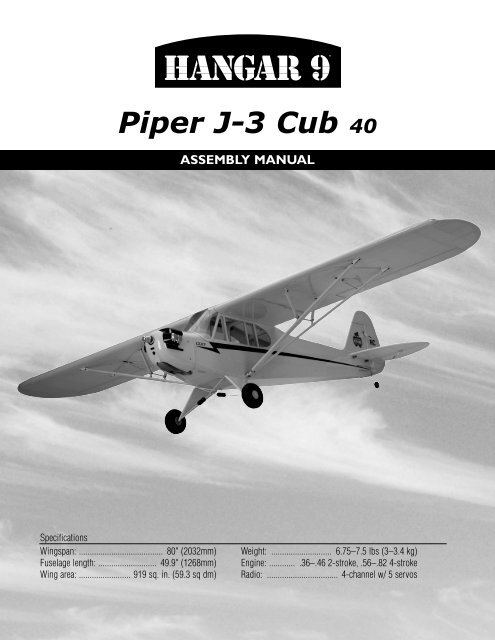
<strong>Piper</strong> J-3 <strong>Cub</strong> <strong>40</strong><br />
ASSEMBLY MANUAL<br />
Specifications<br />
Wingspan: ....................................... 80" (2032mm)<br />
Fuselage length: ........................... 49.9" (1268mm)<br />
Wing area: ........................ 919 sq. in. (59.3 sq dm)<br />
Weight: ............................ 6.75–7.5 lbs (3–3.4 kg)<br />
Engine: ............ .36–.46 2-stroke, .56–.82 4-stroke<br />
Radio: ................................. 4-channel w/ 5 servos
Table of Contents<br />
Contents of Kit . . . . . . . . . . . . . . . . . . . . . . . . . . . . . . . . . . . . . . . . . . . . . . . . . . . . . . . . . . . . . . . . . . . .3<br />
Additional Required Equipment. . . . . . . . . . . . . . . . . . . . . . . . . . . . . . . . . . . . . . . . . . . . . . . . . . . . . . . .3<br />
Covering Colors . . . . . . . . . . . . . . . . . . . . . . . . . . . . . . . . . . . . . . . . . . . . . . . . . . . . . . . . . . . . . . . . . . .3<br />
Additional Required Tools and Adhesives. . . . . . . . . . . . . . . . . . . . . . . . . . . . . . . . . . . . . . . . . . . . . . . .4<br />
Field Equipment Required. . . . . . . . . . . . . . . . . . . . . . . . . . . . . . . . . . . . . . . . . . . . . . . . . . . . . . . . . . . .4<br />
Warning . . . . . . . . . . . . . . . . . . . . . . . . . . . . . . . . . . . . . . . . . . . . . . . . . . . . . . . . . . . . . . . . . . . . . . . . .4<br />
Using the <strong>Manual</strong> . . . . . . . . . . . . . . . . . . . . . . . . . . . . . . . . . . . . . . . . . . . . . . . . . . . . . . . . . . . . . . . . . .4<br />
Before Starting Assembly . . . . . . . . . . . . . . . . . . . . . . . . . . . . . . . . . . . . . . . . . . . . . . . . . . . . . . . . . . . .5<br />
Warranty Information . . . . . . . . . . . . . . . . . . . . . . . . . . . . . . . . . . . . . . . . . . . . . . . . . . . . . . . . . . . . . . .5<br />
Section 1: Hinge Installation. . . . . . . . . . . . . . . . . . . . . . . . . . . . . . . . . . . . . . . . . . . . . . . . . . . . . . . . . .6<br />
Section 2: Engine Installation . . . . . . . . . . . . . . . . . . . . . . . . . . . . . . . . . . . . . . . . . . . . . . . . . . . . . . . . .9<br />
Section 3: Servo Installation (Aileron) . . . . . . . . . . . . . . . . . . . . . . . . . . . . . . . . . . . . . . . . . . . . . . . . .11<br />
Section 4: Servo Installation (Fuselage) . . . . . . . . . . . . . . . . . . . . . . . . . . . . . . . . . . . . . . . . . . . . . . . .15<br />
Section 5: Window Installation . . . . . . . . . . . . . . . . . . . . . . . . . . . . . . . . . . . . . . . . . . . . . . . . . . . . . . .20<br />
Section 6: Landing Gear Installation . . . . . . . . . . . . . . . . . . . . . . . . . . . . . . . . . . . . . . . . . . . . . . . . . . .21<br />
Section 7: Installing the Stabilizer. . . . . . . . . . . . . . . . . . . . . . . . . . . . . . . . . . . . . . . . . . . . . . . . . . . . .23<br />
Section 8: Cowling Installation . . . . . . . . . . . . . . . . . . . . . . . . . . . . . . . . . . . . . . . . . . . . . . . . . . . . . . .26<br />
Section 9: Wing Installation . . . . . . . . . . . . . . . . . . . . . . . . . . . . . . . . . . . . . . . . . . . . . . . . . . . . . . . . .28<br />
Adjusting the Engine. . . . . . . . . . . . . . . . . . . . . . . . . . . . . . . . . . . . . . . . . . . . . . . . . . . . . . . . . . . . . . .31<br />
Control Throws . . . . . . . . . . . . . . . . . . . . . . . . . . . . . . . . . . . . . . . . . . . . . . . . . . . . . . . . . . . . . . . . . . .31<br />
Recommended CG . . . . . . . . . . . . . . . . . . . . . . . . . . . . . . . . . . . . . . . . . . . . . . . . . . . . . . . . . . . . . . . .32<br />
Preflight . . . . . . . . . . . . . . . . . . . . . . . . . . . . . . . . . . . . . . . . . . . . . . . . . . . . . . . . . . . . . . . . . . . . . . . .32<br />
Range Testing the Radio . . . . . . . . . . . . . . . . . . . . . . . . . . . . . . . . . . . . . . . . . . . . . . . . . . . . . . . . . . . .33<br />
2005 Official AMA National Model Aircraft Safety Code. . . . . . . . . . . . . . . . . . . . . . . . . . . . . . . . . . . .34<br />
2
Contents of Kit<br />
C<br />
A<br />
G<br />
E<br />
D<br />
Large Parts:<br />
A. Fuselage HAN<strong>40</strong>02<br />
B. Wing HAN<strong>40</strong>01<br />
C. Cowling HAN<strong>40</strong>04<br />
D. Tail Set HAN<strong>40</strong>03<br />
E. Landing Gear HAN<strong>40</strong>05<br />
F. Wing Strut Set HAN<strong>40</strong>10<br />
G. Window Set HAN<strong>40</strong>08<br />
F<br />
B<br />
Items Not Shown:<br />
Fuel Tank<br />
Tail Wheel Assembly<br />
Decal Set<br />
Pushrod Set<br />
Wheels<br />
Top Fuselage Hatch<br />
HAN<strong>40</strong>07<br />
HAN<strong>40</strong>09<br />
HAN<strong>40</strong>11<br />
HAN<strong>40</strong>06<br />
HAN<strong>40</strong>12<br />
Additional Required Equipment<br />
Radio Equipment<br />
• 4-channel radio system (minimum)<br />
• 5 standard servos<br />
• Receiver<br />
• Receiver battery<br />
• Switch harness<br />
• 12" Servo Extension (JRPA098) (2)<br />
• “Y” Harness (JRPA135)<br />
• Large Arms/Horns w/Screw (JRPA212)<br />
Covering Colors<br />
Recommended JR® Systems<br />
• PCM10X<br />
• XP9303<br />
• XP8103<br />
• X-378<br />
• XP6102<br />
• XF631<br />
• XF421<br />
• Quattro<br />
Recommended Engine<br />
• Evolution® .36–.46<br />
• Saito .56–.82 4-stroke<br />
JR XP6102<br />
JR XP9303<br />
• <strong>Cub</strong> Yellow<br />
• Black<br />
HANU884<br />
HANU874<br />
3
Additional Required Tools and Adhesives<br />
Tools<br />
• Adjustable wrench<br />
• Crimping tool<br />
• Drill<br />
• Drill bit: 1/16”, 5/64”, 3/32”<br />
• Felt-tipped pen<br />
• Heat gun<br />
• Hobby knife<br />
• Hobby scissors<br />
• Petroleum jelly<br />
• Phillips screwdriver (small)<br />
• Phillips screwdriver (large)<br />
• Pliers<br />
• Rotary tool w/sanding drum<br />
• Ruler<br />
• Sandpaper<br />
• String<br />
• Threadlock<br />
• T-pins<br />
Adhesives<br />
• 6-minute epoxy<br />
• Thin CA<br />
• Medium CA<br />
Other Required Items<br />
• Epoxy brushes<br />
• Felt-tipped pen or pencil<br />
• Measuring device (e.g. ruler, tape measure)<br />
• Mixing sticks for epoxy<br />
• Paper towels<br />
• Petroleum jelly<br />
• Rubbing alcohol<br />
• Sanding bar<br />
• Covering Iron (HAN101)<br />
• Covering Glove (HAN150)<br />
• Sealing Iron Sock (HAN141)<br />
Field Equipment Required<br />
• Propeller<br />
• Fuel<br />
• Glow Plug Wrench (HAN2510)<br />
• Glow Plug Igniter with Charger (HAN7101)<br />
• Glow Plug (HAN3001/3006)<br />
• <strong>Manual</strong> Fuel Pump (HAN118)<br />
Warning<br />
An RC aircraft is not a toy! If misused, it can cause serious bodily harm and damage to property. Fly only in open areas,<br />
preferably at AMA (Academy of Model Aeronautics) approved flying sites, following all instructions included with your<br />
radio and engine.<br />
4
Using the <strong>Manual</strong><br />
This manual is divided into sections to help make assembly easier to understand, and to provide breaks between each<br />
major section. Remember to take your time and follow the directions.<br />
Before Starting Assembly<br />
Before beginning the assembly of your J-3 <strong>Cub</strong>, remove each part from its bag for inspection. Closely inspect the<br />
fuselage, wing panels, rudder, and stabilizer and for damage. If you find any damaged or missing parts, contact the place<br />
of purchase.<br />
If you find any wrinkles in the covering, use a heat gun or covering iron to remove them. Use caution while working<br />
around areas where the colors overlap to prevent separating the colors.<br />
HAN100 – Heat Gun<br />
HAN150 – Covering Glove<br />
HAN101 – Covering Iron<br />
HAN141 – Sealing Iron<br />
Sock<br />
Warranty Information<br />
Horizon Hobby, Inc. guarantees this kit to be free from defects in both material and workmanship at the date of purchase.<br />
This warranty does not cover any parts damaged by use or modification. In no case shall Horizon Hobby’s liability exceed<br />
the original cost of the purchased kit. Further, Horizon Hobby reserves the right to change or modify this warranty without<br />
notice.<br />
In that Horizon Hobby has no control over the final assembly or material used for the final assembly, no liability shall be<br />
assumed nor accepted for any damage of or caused by the final user-assembled product. By the act of using the product,<br />
the user accepts all resulting liability.<br />
Once assembly of the model has been started, you must contact Horizon Hobby, Inc. directly regarding any warranty<br />
question that you have. Please do not contact your local hobby store regarding warranty issues, even if that is where you<br />
purchased it. This will enable Horizon to better answer your questions and provide service in the event that you may need<br />
any assistance.<br />
If the buyer or user is not prepared to accept the liability associated with the use of this product, they are advised to<br />
return this kit immediately in new and unused condition to the place of purchase.<br />
For any additional questions please contact:<br />
Horizon Hobby Product Support<br />
4105 Fieldstone Road<br />
Champaign, Illinois 61822<br />
(877) 504-0233<br />
www.horizonhobby.com<br />
5
Section 1: Hinge Installation<br />
Required Parts<br />
• Stabilizer<br />
• Elevator<br />
• Fuselage<br />
• Rudder<br />
• Wing<br />
• Aileron (R&L)<br />
• Tail gear wire • Hinge (17)<br />
Step 3<br />
Place the hinges in the stabilizer.<br />
Required Tools and Adhesives<br />
• Thin CA<br />
• T-pins<br />
• 6-minute epoxy<br />
• Petroleum jelly<br />
• Drill • Drill bit: 1/16", 3/32"<br />
• Hobby knife<br />
Step 1<br />
Locate three hinges. Place a T-pin in the center of<br />
each hinge.<br />
Step 4<br />
Slide the elevator and stabilizer together. Remove the<br />
T-pins. There should be a 1/64" gap between the<br />
stabilizer and elevator.<br />
Step 2<br />
Drill a 1/16" hole in both a stabilizer and elevator half in<br />
the center of the hinge locations.<br />
Step 5<br />
Check that the tips of the stabilizer and elevator are<br />
aligned. Wick thin CA into each of the hinges.<br />
Note: Do not use accelerator in the hinging<br />
process. The CA must be allowed to soak into<br />
the hinge naturally.<br />
6
Section 1: Hinge Installation<br />
Step 6<br />
After the CA has cured, flex the surfaces several times to<br />
break in the hinges.<br />
Step 9<br />
Coat the tail gear wire near the bushing with petroleum<br />
jelly. Work the lubricant into the bearing to prevent epoxy<br />
from entering the bearing, gluing the bearing to the wire.<br />
Step 7<br />
Pull on both surfaces to make sure the hinges are secure.<br />
Step 10<br />
Drill a 3/32" hole in the rudder 1 1 / 4<br />
" from the bottom.<br />
Step 8<br />
Repeat Steps 1 through 7 for the aileron hinges. Each<br />
aileron will use four hinges. Center the ailerons and make<br />
sure they are not binding before gluing the hinges.<br />
7
Section 1: Hinge Installation<br />
Step 11<br />
Cut a groove from the hole to the bottom of the rudder to<br />
allow clearance for the tail gear bearing.<br />
Step 13<br />
Cut a slot in the end of the fuselage to accept the tail<br />
gear bearing.<br />
Step 12<br />
Apply a thin layer of lubricant where the bearing will<br />
ride in the rudder. Use 6-minute epoxy to glue the wire<br />
into the rudder.<br />
Step 14<br />
Install three hinges into the rudder. Test fit the rudder<br />
to the fuselage, sliding the hinges and tail wheel bracket<br />
into position.<br />
Step 15<br />
Use 6-minute epoxy to glue the tail gear bearing into the<br />
fuselage. Use thin CA for the hinges.<br />
8
Section 2: Engine Installation<br />
Required Parts<br />
• Fuselage assembly • Fuel tank assembly<br />
• Engine mount<br />
• 8-32 x 3/4" bolt (4) • 8-32 X 1" bolt (4)<br />
• 8-32 lock nut (4) • #8 washer (4)<br />
• 14 1 / 4<br />
" pushrod wire • Clevis<br />
• Clevis retainer<br />
• Engine mount plate (2)<br />
Step 2<br />
Position the engine so the drive washer is 4 1 / 2<br />
"<br />
forward of the firewall. Use the engine mount plates,<br />
8-32 x 1" bolts, 8-32 lock nuts and #8 washers to attach<br />
the engine to the mount. The engine mounting lugs are<br />
sandwiched between the engine mount plates and the<br />
engine mount. Tighten the bolts evenly.<br />
Required Tools and Adhesives<br />
• Engine w/muffler • Threadlock<br />
• Ruler<br />
• Phillips screwdriver<br />
Step 1<br />
Secure the engine mount to the firewall using four<br />
8-32 x 3/4" bolts. Use threadlock to prevent the bolts<br />
from vibrating loose during flight.<br />
Note: The engine mount plates have texture<br />
on one side, which is placed against the<br />
engine mounting lugs.<br />
Step 3<br />
Place a clevis retainer onto a clevis. Thread the clevis<br />
onto the 14 1 / 4<br />
" pushrod wire. Slide the wire into the<br />
pushrod tube in the fuselage. Attach the clevis to the<br />
carburetor arm.<br />
9
Section 2: Engine Installation<br />
Step 4<br />
Attach the muffler to the engine using the hardware<br />
provided with your particular engine.<br />
Step 7<br />
Attach the vent line to the muffler and the line from the<br />
clunk to the carburetor.<br />
Note: It may be necessary to rotate the end of<br />
the muffler to point the stinger straight down,<br />
away from the fuselage.<br />
Step 5<br />
Check the tank and note which fuel line is vent and which<br />
is attached to the clunk. Make a note of the line colors<br />
and which they correspond to. Also note the direction<br />
of the vent line inside the fuel tank so it faces toward the<br />
top of the fuselage.<br />
Step 8<br />
A Saito 4-stroke can be installed instead of a 2-stroke<br />
engine. You will have to relocate the throttle pushrod to<br />
line up with the throttle arm on the carburetor.<br />
Step 6<br />
With the vent line up, slide the fuel tank into the fuselage.<br />
10
Section 3: Servo Installation (Aileron)<br />
Required Parts<br />
• Wing (L&R)<br />
• Servo hatch (L&R)<br />
• #2 x 3/8" screw (8) • Control horn (2)<br />
• 2mm x 20mm screw (6) • Clevis (2)<br />
• Clevis retainer (2)<br />
• 4 3 / 4<br />
" pushrod wire (2)<br />
• Pushrod wire keeper (2)<br />
Step 2<br />
Install the recommended servo hardware (grommets and<br />
eyelets) supplied with the servo. Temporarily install a long<br />
half servo arm (JRPA212) onto the servo and position<br />
the servo onto the hatch so the servo arm is centered in<br />
the notch. Once satisfied, mark the location for the servo<br />
mounting blocks using a felt-tipped pen.<br />
Required Tools and Adhesives<br />
• Phillips screwdriver (small) • 6-minute epoxy<br />
• Felt-tipped pen<br />
• String<br />
• Drill • Drill bit: 1/16", 3/32"<br />
• Pliers<br />
• “Y” harness<br />
• 12" servo extension (2) • Hobby knife<br />
• Long Servo Arm (JRPA212) (2)<br />
Step 1<br />
Remove the covering from the servo opening in the<br />
bottom of the wing using a hobby knife. Select the correct<br />
servo hatch by checking the alignment for the servo arm<br />
on the plate with the one on the wing.<br />
Step 3<br />
Locate the 3/8" x 3/4" x 3/4" servo mounting blocks.<br />
Use 6-minute epoxy to glue the blocks to the hatch. Let<br />
the epoxy fully cure before proceeding to the next step.<br />
11
Section 3: Servo Installation (Aileron)<br />
Step 4<br />
Place the aileron servo between the mounting blocks and<br />
use a felt-tipped pen to mark the location of the four servo<br />
mounting screws. Note that the servo must not touch the<br />
hatch in order to isolate engine vibration.<br />
Step 6<br />
Connect a 12" Servo Lead Extension (JRPA098) to the<br />
servo lead. Secure the connectors by tying them in<br />
a knot using dental floss or by using a commercially<br />
available connector clamp to prevent the servo leads from<br />
becoming disconnected.<br />
Note: Before mounting the servo,<br />
electronically center the servo using the<br />
transmitter, then install the servo arm to<br />
avoid having to remove the servo and center<br />
the arm later. It may be necessary to slightly<br />
trim one of the servo mounting blocks to clear<br />
the servo wire.<br />
Note: It is always a good idea to secure<br />
the servo connector and servo extension<br />
together to prevent the wires from<br />
becoming unplugged.<br />
Step 5<br />
Remove the servo and use a 1/16" drill bit to pre-drill<br />
the holes for the servo mounting screws marked in the<br />
previous step. Use the screws supplied with the servo to<br />
mount it to the servo mounting blocks.<br />
12
Section 3: Servo Installation (Aileron)<br />
Step 7<br />
Tie a wheel collar onto a piece of string. Drop the wheel<br />
collar into the wing from the root and retrieve it from the<br />
servo opening.<br />
Step 8<br />
Tie the string onto the servo extension. Gently pull the<br />
extension through the wing using the string. Untie the<br />
string when the servo lead has been pulled through. Use<br />
tape to secure the servo lead to the wing to prevent it from<br />
falling back into the wing panel.<br />
Step 9<br />
Secure the hatch using four #2 x 3/8" screws.<br />
13
Section 3: Servo Installation (Aileron)<br />
Step 10<br />
Place a clevis retainer onto a clevis. Thread the clevis<br />
onto a 4 3 / 4<br />
" pushrod wire. Remove the backplate<br />
from a control horn, and then attach the clevis to the<br />
control horn.<br />
Step 12<br />
Drill the locations marked in the previous step using<br />
a 3/32" drill bit.<br />
Step 11<br />
Position the control horn on the aileron. Use the<br />
pushrod wire as a guide to align the horn to the servo<br />
arm. Position the horn so the holes align with the hinge<br />
line. Use a felt-tipped pen to mark the positions for the<br />
three mounting bolts.<br />
Step 13<br />
Place a few drops of thin CA into each of the holes to<br />
harden the balsa. Attach the control horn using three<br />
2mm x 20mm screws and the control horn backplate.<br />
14
Section 3: Servo Installation (Aileron)<br />
Step 14<br />
Plug in the aileron servo to the radio system. Center the<br />
trims on the transmitter to center the aileron servo. Hold<br />
the aileron in neutral. Use a felt-tipped pen to mark the<br />
pushrod wire where it crosses the servo arm.<br />
Step 15<br />
Bend the pushrod wire at the mark. Use a pushrod wire<br />
keeper to secure the pushrod wire to the servo arm.<br />
Step 16<br />
Repeat Steps 1 though 15 for the remaining wing panel.<br />
Section 4: Servo Installation (Fuselage)<br />
Required Parts<br />
• Fuselage<br />
• Clevis<br />
• Clevis retainer<br />
• Control horn<br />
• Wing strut mount (2) • #4 x 3/8" screw (4)<br />
• 19 3 / 4<br />
" pushrod dowel • 6" pushrod wire<br />
• Pushrod wire (32”)<br />
• 2 1 / 8<br />
" heat shrink tubing (2)<br />
• 2mm x 12mm screw (3)<br />
• 7 1 / 4<br />
" pushrod wire (2)<br />
Step 1<br />
Remove the covering for the wing strut mount. The<br />
opening is located above the rear landing gear mount.<br />
Required Tools and Adhesives<br />
• Phillips screwdriver • Hobby knife<br />
• Drill • Drill bit: 3/32", 5/64"<br />
• Heat gun<br />
• Medium CA<br />
• Thin CA<br />
• Felt-tipped pen<br />
15
Section 4: Servo Installation (Fuselage)<br />
Step 2<br />
Slide the wing strut mount into the opening. Secure the<br />
mount using two #4 x 3/8" screws.<br />
Step 5<br />
Place a clevis retainer onto a clevis. Thread the clevis<br />
onto a 32" pushrod wire. Remove the backplate from a<br />
control horn, and then attach the clevis to the control<br />
horn. Slide the pushrod into the rudder pushrod tube in<br />
the fuselage. Position the horn so the holes align with the<br />
hinge line. Use a felt-tipped pen to mark the positions for<br />
the three mounting bolts.<br />
Step 3<br />
Install the recommended servo hardware (grommets and<br />
eyelets) supplied with the servos into the throttle, rudder,<br />
and elevator servos.<br />
Step 4<br />
Use the hardware provided with the servos to mount them<br />
in the fuselage.<br />
Step 6<br />
Drill the locations marked in the previous step using<br />
a 3/32" drill bit. Place a few drops of thin CA into<br />
each of the holes to harden the balsa. Attach the control<br />
horn using three 2mm x 12mm screws and the control<br />
horn backplate.<br />
16
Section 4: Servo Installation (Fuselage)<br />
Step 7<br />
Plug in the rudder servo to the radio system. Center the<br />
trims on the transmitter to center the rudder servo. Hold<br />
the rudder in neutral. Use a felt-tipped pen to mark the<br />
pushrod wire where it crosses the servo arm.<br />
Step 9<br />
Center the throttle stick and trim with both the receiver<br />
and transmitter on. Install the throttle servo arm in the<br />
neutral position.<br />
Step 8<br />
Remove the pushrod wire from the fuselage and remove<br />
the clevis. Bend the pushrod wire at the mark. Slide<br />
the pushrod back into the fuselage from the radio<br />
compartment, and then put the clevis back onto the<br />
wire. Use a pushrod wire keeper to secure the pushrod<br />
wire to the servo arm.<br />
Step 10<br />
Move the throttle stick and trim lever down to the throttle<br />
closed position. <strong>Manual</strong>ly close the carburetor and mark<br />
the throttle pushrod where it crosses the servo arm.<br />
17
Section 4: Servo Installation (Fuselage)<br />
Step 11<br />
Remove the pushrod wire from the fuselage and remove<br />
the clevis. Bend the pushrod wire at the mark. Slide<br />
the pushrod back into the fuselage from the radio<br />
compartment, and then put the clevis back onto the<br />
wire. Use a pushrod wire keeper to secure the pushrod<br />
wire to the servo arm.<br />
Step 14<br />
Cut a groove into the pushrod from the hole to the end<br />
of the pushrod. Repeat for the opposite side so you end<br />
up with two grooves. The elevator pushrod wires will<br />
rest in these grooves.<br />
Step 15<br />
Locate the two 7 1 / 4<br />
" pushrod wires. Make a bend in one<br />
wire 1/4" from the non-threaded end of one of the wires.<br />
The remaining pushrod is bent 1/2" from the end.<br />
Step 12<br />
Check the movement of the throttle to verify there is no<br />
binding at either low or high throttle. If there is, make the<br />
necessary adjustment to eliminate any binding. Install the<br />
throttle servo arm screw when complete.<br />
Step 13<br />
Locate the 19 3 / 4<br />
" wood pushrod for the elevator. Drill two<br />
5/64" holes through the dowel, 1" and 1 1 / 4<br />
", from one<br />
end. The holes must be parallel to each other.<br />
Step 16<br />
Test fit the two wires. The wire bent at 1/2" is placed in<br />
the hole closest to the pushrod end. You will have to<br />
trim the wire down after the bend so it won’t interfere<br />
with the other pushrod. Once fit, use medium CA to<br />
glue the wires to the dowel.<br />
18
Section 4: Servo Installation (Fuselage)<br />
Step 17<br />
Slide the 2 1 / 8<br />
" piece of heat shrink over the wires and<br />
dowel. Use a heat gun or lighter to shrink the tubing. Once<br />
the tubing has been shrunk, apply thin CA to each end of<br />
the shrink to complete this part of the pushrod assembly.<br />
Step 20<br />
Plug the necessary servo leads into the receiver. This<br />
includes the switch harness and battery leads as well.<br />
Install the flat radio foam into the fuselage, followed by the<br />
die-cut foam. Place the receiver and battery into the foam.<br />
Step 18<br />
Repeat Steps 13 through 17 for the opposite end of<br />
the dowel, but only drill one hole and prepare one 6"<br />
pushrod wire.<br />
Step 19<br />
Slide the elevator pushrod wire in position into the<br />
fuselage. It may take some time to get it in, so be<br />
patient. Slide a clevis retainer onto two clevises, and<br />
then thread them onto the pushrod wires at the aft end<br />
of the fuselage. This will prevent the pushrod wire from<br />
falling out of the fuselage.<br />
Note: There is a tube located under the<br />
elevator servo for the antenna wire. Route the<br />
wire through this tube to the tail of the aircraft.<br />
Step 21<br />
Place the remaining flat radio foam over the receiver and<br />
battery. Secure the foam to prevent the receiver and battery<br />
from moving from their location. Mount the receiver<br />
switch to the side of the fuselage.<br />
19
Section 5: Window Installation<br />
Required Parts<br />
• Side window (L&R)<br />
• Support (2)<br />
• Front windscreen<br />
• Fuselage hatch<br />
Step 3<br />
Cut and fit the two supports to the fuselage. Use medium<br />
CA to glue them into position.<br />
Required Tools and Adhesives<br />
• Hobby scissors<br />
• Canopy glue<br />
• Hobby knife<br />
Step 1<br />
Use hobby scissors and a hobby knife to trim the side<br />
windows from their sheets. Leave a 1/8" lip to glue the<br />
windows to the fuselage.<br />
Step 4<br />
Test fit the front windscreen into position. Trim as<br />
necessary. Use canopy glue to secure the front<br />
windscreen to the fuselage.<br />
Step 2<br />
Test fit the windows from the inside of the fuselage. Trim<br />
them as necessary so they fit flush to the outside of the<br />
fuselage. Use canopy glue to secure the windows into the<br />
fuselage. Install the window into the fuselage hatch at this<br />
time as well.<br />
Note: You can use epoxy as well, but be<br />
very careful not to get epoxy on the nice clear<br />
windows.<br />
20
Section 6: Landing Gear Installation<br />
Required Parts<br />
• Landing gear<br />
• 3.35" (85mm) wheel (2) • Wheel cap (2)<br />
• Inner wheel hub (2) • Outer wheel hub (2)<br />
• 1" (25mm) wheel • Landing gear strap (4)<br />
• 2mm x 14mm screw (8)<br />
• Large wheel collar w/setscrew (4)<br />
• 3mm x 10mm screw (8)<br />
• Small wheel collar w/setscrew<br />
Step 2<br />
Position the 3.35" (85mm) wheel onto the inner hub.<br />
Attach the outer wheel hub to the inner wheel hub using<br />
four 2mm x 14mm screws. The screws go through the<br />
outer wheel hub and into the inner wheel hub.<br />
Required Tools and Adhesives<br />
• Phillips screwdriver (small) • Hex wrench<br />
• Hobby knife<br />
• Sandpaper<br />
Step 1<br />
Use a hobby knife to scrape away the paint on the landing<br />
gear where the wheel will be located. Slide the inner wheel<br />
hub onto the axle. Next, slide a large wheel collar 3/8"<br />
from the end of the axle and secure it using the setscrew.<br />
Step 3<br />
Snap the wheel cap onto the wheel.<br />
Step 4<br />
Repeat Steps 1 through 3 for the remaining wheel.<br />
21
Section 6: Landing Gear Installation<br />
Step 5<br />
Position the landing gear to the bottom of the fuselage.<br />
Secure the position of the gear using four landing gear<br />
straps and eight 3mm x 10mm screws.<br />
Step 6<br />
Secure the tail wheel using the small wheel collar<br />
and setscrew.<br />
22
Section 7: Installing the Stabilizer<br />
Required Parts<br />
• Stabilizer assembly • Fuselage<br />
• #4 washer (4) • #2 washer (3)<br />
• 2-56 x 1/2" screw (3) • 2-56 nut (3)<br />
• Clevis (4) • Clevis retainer (4)<br />
• Cable ends (4) • Brass crimps (8)<br />
• Cable<br />
• Pushrod wire keeper<br />
• Control horn (2)<br />
• 2mm x 12mm screw (6)<br />
• Brass fitting (small) (6)<br />
• Brass fitting (large) (2)<br />
• #2 x 1/2" sheet metal screw<br />
• 4-<strong>40</strong> x 1/2" socket head screw (4)<br />
Required Tools and Adhesives<br />
• Threadlock<br />
• Pliers<br />
• Drill • Drill bit: 3/32"<br />
• Adjustable wrench • Crimping tool<br />
• Phillips screwdriver (small)<br />
Step 1<br />
Slide the stabilizer halves into the slot in the fuselage.<br />
Use four 4-<strong>40</strong> x 1/2" screws and four #4 washers to<br />
secure the stabilizer. Use threadlock to prevent the<br />
screws from vibrating loose during flight.<br />
Step 2<br />
Attach a control horn to one of the elevator clevises. Line<br />
the holes in the control horn with the hinge line and mark<br />
the location for the mounting crews onto the elevator.<br />
Step 3<br />
Drill the holes using a 3/32" drill bit. Use thin CA to<br />
harden the holes. Mount the control horn using the horn<br />
backplate and three 2mm x 12mm screws.<br />
23
Section 7: Installing the Stabilizer<br />
Step 4<br />
Repeat Steps 2 and 3 for the remaining elevator<br />
control horn.<br />
Step 5<br />
Attach the elevator pushrod to the servo arm of the<br />
elevator servo using a pushrod wire keeper.<br />
Step 8<br />
Attach the small brass fitting to the fin and stabilizer<br />
using 2-56 x 1/2" screws, #2 washers and 2-56 nuts.<br />
Fittings are placed on both sides of the rudder and<br />
the top and bottom of the stabilizer.<br />
Step 6<br />
Bend each of the fittings (small and large) to about a<br />
45-degree angle.<br />
Step 7<br />
Attach the large brass fittings at the bottom rear of the<br />
fuselage using the #2 x 1/2" sheet metal screw.<br />
Step 9<br />
Slide a clevis retainer onto a clevis. Thread a cable end<br />
into the clevis. Prepare four of these connectors.<br />
24
Section 7: Installing the Stabilizer<br />
Step 10<br />
Cut the cable into four equal pieces. Prepare one cable by<br />
sliding the cable through a crimp, through the cable end,<br />
then back through the crimp twice. Pull the excess cable<br />
tight and use a crimping tool to complete the job. Repeat<br />
for all four of the ends.<br />
Step 11<br />
Attach the four connectors to the brass fittings<br />
of the stabilizer.<br />
Step 12<br />
Repeat Step 10, only passing the cable through the brass<br />
fittings instead of the cable ends. The cables should have<br />
very light tension.<br />
25
Section 8: Cowling Installation<br />
Required Parts<br />
• Fuselage<br />
• Propeller<br />
• #2 x 3/8" sheet metal screw (4)<br />
Required Tools and Adhesives<br />
• Phillips screwdriver (small) • Ruler<br />
• Drill • Drill bit: 1/16", 5/64"<br />
• Hobby scissors<br />
• Felt-tipped pen<br />
• Rotary tool w/sanding drum<br />
Step 3<br />
Remove the engine and slide the cowling onto the<br />
fuselage. Position it so the opening for the crankshaft is<br />
4 1 / 8<br />
" forward of the firewall. Transfer the locations from<br />
the card stock onto the cowling using a felt-tipped pen.<br />
Step 1<br />
Remove the propeller nut and washer from the engine.<br />
Position the drive washer so it is keyed onto the engine<br />
shaft. Slide the spinner backplate onto the engine shaft,<br />
and then slide the propeller into position.<br />
Step 2<br />
Use card stock taped to the fuselage to indicate the<br />
locations for the needle valve, cylinder head, muffler, and<br />
any other items that will extend outside the cowling.<br />
Step 4<br />
Carefully trim the cowling to fit over the engine. Work<br />
slowly and remove small amounts of material at a time.<br />
Use card stock to indicate the sides of the fuselage.<br />
Slide the cowl in position, allowing the drive washer to<br />
extend 1/8" forward of the cowl, then mark the positions<br />
for the cowling screws.<br />
26
Section 8: Cowling Installation<br />
Step 5<br />
Drill 1/16" holes through the cowl and into the fuselage<br />
sides at the locations marked in the last step. Enlarge the<br />
holes in the cowl using a 5/64" drill bit. Secure the cowl<br />
to the fuselage using four #2 x 3/8" screws.<br />
Step 6<br />
Attach the propeller following the instructions provided<br />
with your particular engine.<br />
27
Section 9: Wing Installation<br />
Required Parts<br />
• Wing<br />
• Fuselage<br />
• 4-<strong>40</strong> lock nut (16) • 4-<strong>40</strong> nut (4)<br />
• Strut support anchor (4) • Strut bracket (4)<br />
• Strut end (4)<br />
• Strut (narrow) (L&R)<br />
• Strut (wide) (L&R) • Strut brace (long) 2<br />
• Strut brace (short) (2) • Strut cross brace (2)<br />
• #2 x 3/8" screw (4) • Fuselage hatch<br />
• 1/4-20 x 2" nylon bolt (2)<br />
• 4-<strong>40</strong> x 1/2" socket head screw (24)<br />
Step 2<br />
Thread the strut support anchors into the holes in the<br />
wing. The anchors have external threads.<br />
Required Tools and Adhesives<br />
• Hex wrench<br />
• Adjustable wrench<br />
• Threadlock<br />
• Phillips screwdriver (small)<br />
Step 1<br />
Attach two strut brackets to the bottom of the wing using<br />
four 4-<strong>40</strong> x 1/2" socket head screws. Use threadlock to<br />
prevent the screws from loosening during flight.<br />
Step 3<br />
Attach the strut to the strut brackets using two 4-<strong>40</strong> x 1/2"<br />
socket head screws and two 4-<strong>40</strong> lock nuts. The wide strut<br />
goes towards the leading edge, the narrow strut towards<br />
the trailing edge.<br />
Note: The airfoil of the struts matches the<br />
direction of the wing. The struts also have<br />
fittings in the center, which will face towards<br />
the wing when installed.<br />
28
Section 9: Wing Installation<br />
Step 4<br />
Thread a 4-<strong>40</strong> nut onto the threaded end of the strut.<br />
Thread a strut end onto the strut. The nut will be used<br />
once the strut has been adjusted.<br />
Step 5 Photo<br />
Step 6<br />
Slide the wing tube into the wing panel. Slide the tube and<br />
panel into position on the fuselage.<br />
Step 5<br />
Install the short strut brace to the rear strut support<br />
anchor and the long strut brace to the front strut support<br />
anchor using 4-<strong>40</strong> x 1/2" socket head screws and<br />
4-<strong>40</strong> nuts. Attach the strut supports and the strut cross<br />
brace using two 4-<strong>40</strong> x 1/2" socket head screws and<br />
two 4-<strong>40</strong> lock nuts.<br />
Step 7<br />
Secure the wing panel using a 1/4-20 x 2" nylon bolt.<br />
29
Section 9: Wing Installation<br />
Step 8<br />
Support the fuselage so the wing is not resting on the<br />
work surface. Adjust the strut end so it aligns with the<br />
wing strut mount. Attach the wing struts using two<br />
4-<strong>40</strong> x 1/2" socket head bolts and two 4-<strong>40</strong> locking<br />
nuts. Once attached, tighten the 4-<strong>40</strong> nuts on the strut to<br />
prevent the end from rotating when the wing is removed<br />
for storage.<br />
Step 9<br />
Repeat Steps 1 through 8 to install the remaining wing<br />
panel and strut.<br />
Step 10<br />
Install the fuselage hatch using four #2 x 3/8" screws.<br />
Note: When removing the wing, simply<br />
disconnect the bolts holding the strut to the<br />
fuselage. This will make things much easier<br />
when installing the wing at the field.<br />
Note: The struts on the J-3 <strong>Cub</strong> are<br />
functional, so be sure all bolts and nuts<br />
are tight before flying. Failure to do so<br />
could result in wing failure.<br />
30
Adjusting the Engine<br />
Step 1<br />
Completely read the instructions included with your<br />
engine and follow the recommended break-in procedure.<br />
Step 2<br />
At the field, adjust the engine to a slightly rich setting at<br />
full throttle and adjust the idle and low-speed needle so<br />
that a consistent idle is achieved.<br />
Step 3<br />
Before you fly, be sure that your engine idles reliably,<br />
transitions and runs at all throttle settings. Only<br />
when this is achieved should any plane be considered<br />
ready for flight.<br />
Control Throws<br />
The amount of control throw should be adjusted as closely<br />
as possible using mechanical means, rather than making<br />
large changes electronically at the radio. By moving<br />
the position of the clevis at the control horn toward the<br />
outermost hole, you will decrease the amount of control<br />
throw of the control surface. Moving it toward the control<br />
surface will increase the amount of throw. Moving the<br />
pushrod wire at the servo arm will have the opposite<br />
effect: Moving it closer to center will decrease throw,<br />
and away from center will increase throw. Work with a<br />
combination of the two to achieve the closest or exact<br />
control throws listed.<br />
Elevator<br />
Low Rate<br />
High Rate<br />
11/16" (11.5º) Up 9/16" (10º) Down<br />
1 1 / 4<br />
" (19.5º) Up 1" (18º) Down<br />
Aileron<br />
Low Rate<br />
High Rate<br />
Rudder<br />
3/8" (8º) Up 1/2" (9º) Down<br />
7/8" (21º) Up 1 1 / 16<br />
" (22º) Down<br />
Linear measurement (inches) measured at root.<br />
1 1 / 2<br />
" (28º) Left 1 1 / 2<br />
" (28º) Right<br />
Linear measurement (inches) measured at front<br />
of counterbalance.<br />
Linear measurement (Inches) measured at<br />
widest part of elevator (roughly in the center).<br />
Note: Use the Low Rate for most flying. The<br />
High Rate is used specifically for performing<br />
spin maneuvers.<br />
31
Recommended CG<br />
An important part of preparing the aircraft for flight is<br />
properly balancing the model. This is especially important<br />
when various engines are mounted.<br />
Caution: Do not inadvertently skip this step!<br />
The recommended Center of Gravity (CG) range for the<br />
<strong>Piper</strong> J-3 <strong>Cub</strong> is 3 1 / 4<br />
" (82.5mm) behind the leading edge<br />
of the wing against the fuselage. It is suggested to start at<br />
the forward end of the range until comfortable with the<br />
flight characteristics of your aircraft. If necessary, move<br />
the battery pack or add weight to either the nose or the<br />
tail until the correct balance is achieved. Stick-on<br />
weights are available at your local hobby shop and work<br />
well for this purpose.<br />
Preflight<br />
Range Test Your Radio<br />
Step 1<br />
Before going to the field, be sure that your batteries<br />
are fully charged, per the instructions included with<br />
your radio. Charge both the transmitter and receiver<br />
pack for your airplane. Use the recommended charger<br />
supplied with your particular radio system, following the<br />
instructions provided with the radio. In most cases the<br />
radio should be charged the night before going out flying.<br />
Step 2<br />
Before each flying session, be sure to range check your<br />
radio. See your radio manual for the recommended<br />
range and instructions for your radio system. Each radio<br />
manufacturer specifies different procedures for their<br />
radio systems. Next, start the engine. With the model<br />
securely anchored, check the range again. The range test<br />
should not be significantly affected. If it is, don’t attempt<br />
to fly! Have your radio equipment checked out by the<br />
manufacturer.<br />
Step 3<br />
Double-check that all controls (aileron, elevator, rudder<br />
and throttle) move in the correct direction.<br />
Step 4<br />
Check the radio installation and make sure all the<br />
control surfaces are moving correctly (i.e. the correct<br />
direction and with the recommended throws). Test<br />
run the engine and make sure it transitions smoothly<br />
from idle to full throttle and back. Also ensure the engine<br />
is tuned according to the manufacturer’s instructions,<br />
and it will run consistently and constantly at full throttle<br />
when adjusted.<br />
Check all the control horns, servo horns, and clevises to<br />
make sure they are secure and in good condition. Replace<br />
any items that would be considered questionable. Failure<br />
of any of these components in flight would mean the loss<br />
of your aircraft.<br />
Note: Keep loose items that can get entangled<br />
in the propeller away from the prop. These<br />
included loose clothing, or other objects such<br />
as pencils and screwdrivers. Especially keep<br />
your hands away from the propeller.<br />
32
Range Testing the Radio<br />
Before each flying session, range-check your radio.<br />
This is accomplished by turning on your transmitter<br />
with the antenna collapsed. Turn on the radio in your<br />
airplane. With your airplane on the ground, you should<br />
be able to walk 30 paces away from your airplane and<br />
still have complete control of all functions. If not, don’t<br />
attempt to fly! Have your radio equipment checked out<br />
by the manufacturer.<br />
33
2005 Official AMA<br />
National Model Aircraft Safety Code<br />
GENERAL<br />
1) I will not fly my model aircraft in sanctioned<br />
events, air shows or model flying demonstrations until<br />
it has been proven to be airworthy by having been<br />
previously, successfully flight tested.<br />
2) I will not fly my model higher than approximately<br />
<strong>40</strong>0 feet within 3 miles of an airport without notifying<br />
the airport operator. I will give right-of-way and avoid<br />
flying in the proximity of full-scale aircraft. Where<br />
necessary, an observer shall be utilized to supervise<br />
flying to avoid having models fly in the proximity of<br />
full-scale aircraft.<br />
3) Where established, I will abide by the safety rules<br />
for the flying site I use, and I will not willfully and<br />
deliberately fly my models in a careless, reckless and/<br />
or dangerous manner.<br />
4) The maximum takeoff weight of a model is 55<br />
pounds, except models flown under Experimental<br />
Aircraft rules.<br />
5) I will not fly my model unless it is identified with<br />
my name and address or AMA number, on or in the<br />
model. (This does not apply to models while being<br />
flown indoors.)<br />
6) I will not operate models with metal-bladed<br />
propellers or with gaseous boosts, in which gases<br />
other than air enter their internal combustion<br />
engine(s); nor will I operate models with extremely<br />
hazardous fuels such as those containing<br />
tetranitromethane or hydrazine.<br />
7) I will not operate models with pyrotechnics (any<br />
device that explodes, burns, or propels a projectile<br />
of any kind) including, but not limited to, rockets,<br />
explosive bombs dropped from models, smoke<br />
bombs, all explosive gases (such as hydrogen-filled<br />
balloons), or ground mounted devices launching a<br />
projectile. The only exceptions permitted are rockets<br />
flown in accordance with the National Model Rocketry<br />
Safety Code or those permanently attached (as per<br />
JATO use); also those items authorized for Air Show<br />
Team use as defined by AST Advisory Committee<br />
(document available from AMA HQ). In any case,<br />
models using rocket motors as a primary means of<br />
propulsion are limited to a maximum weight of 3.3<br />
pounds and a G series motor. (A model aircraft is<br />
defined as an aircraft with or without engine, not able<br />
to carry a human being.)<br />
8) I will not consume alcoholic beverages prior to,<br />
nor during, participation in any model operations.<br />
9) Children under 6 years old are only allowed<br />
on the flight line as a pilot or while receiving<br />
flight instruction.<br />
RADIO CONTROL<br />
1) I will have completed a successful radio equipment<br />
ground range check before the first flight of a new or<br />
repaired model.<br />
2) I will not fly my model aircraft in the presence<br />
of spectators until I become a qualified flier, unless<br />
assisted by an experienced helper.<br />
3) At all flying sites a straight or curved line(s) must<br />
be established in front of which all flying takes place<br />
with the other side for spectators. Only personnel<br />
involved with flying the aircraft are allowed at or in<br />
the front of the flight line. Intentional flying behind the<br />
flight line is prohibited.<br />
4) I will operate my model using only radio control<br />
frequencies currently allowed by the Federal<br />
Communications Commission. (Only properly<br />
licensed Amateurs are authorized to operate<br />
equipment on Amateur Band frequencies.)<br />
34
2005 Official AMA<br />
National Model Aircraft Safety Code<br />
5) Flying sites separated by three miles or more<br />
are considered safe from site-to site interference,<br />
even when both sites use the same frequencies. Any<br />
circumstances under three miles separation require<br />
a frequency management arrangement, which may<br />
be either an allocation of specific frequencies for<br />
each site or testing to determine that freedom from<br />
interference exists. Allocation plans or interference<br />
test reports shall be signed by the parties involved<br />
and provided to AMA Headquarters. Documents of<br />
agreement and reports may exist between (1) two<br />
or more AMA Chartered Clubs, (2) AMA clubs and<br />
individual AMA members not associated with AMA<br />
Clubs, or (3) two or more individual AMA members.<br />
6) For Combat, distance between combat engagement<br />
line and spectator line will be 500 feet per cubic<br />
inch of engine displacement. (Example: .<strong>40</strong> engine<br />
= 200 feet.); electric motors will be based on<br />
equivalent combustion engine size. Additional safety<br />
requirements will be per the RC Combat section of the<br />
current Competition Regulations.<br />
7) At air shows or model flying demonstrations, a<br />
single straight line must be established, one side of<br />
which is for flying, with the other side for spectators.<br />
8) With the exception of events flown under AMA<br />
Competition rules, after launch, except for pilots or<br />
helpers being used, no powered model may be flown<br />
closer than 25 feet to any person.<br />
9) Under no circumstances may a pilot or other<br />
person touch a powered model in flight.<br />
Organized RC Racing Event<br />
10) An RC racing event, whether or not an AMA Rule<br />
Book event, is one in which model aircraft compete<br />
in flight over a prescribed course with the objective of<br />
finishing the course faster to determine the winner.<br />
A. In every organized racing event in which contestants,<br />
callers and officials are on the course:<br />
1. All officials, callers and contestants must properly<br />
wear helmets, which are OSHA, DOT, ANSI, SNELL or<br />
NOCSAE approved or comparable standard while on<br />
the racecourse.<br />
2. All officials will be off the course except for the<br />
starter and their assistant.<br />
3. "On the course” is defined to mean any area<br />
beyond the pilot/staging area where actual flying<br />
takes place.<br />
B. I will not fly my model aircraft in any organized<br />
racing event which does not comply with paragraph A<br />
above or which allows models over 20 pounds unless<br />
that competition event is AMA sanctioned.<br />
C. Distance from the pylon to the nearest spectator<br />
(line) will be in accordance with the current<br />
Competition Regulations under the RC Pylon Racing<br />
section for the specific event pending two or three<br />
pylon course layout.<br />
11) RC night flying is limited to low-performance<br />
models (less than 100 mph). The models must be<br />
equipped with a lighting system that clearly defines<br />
the aircraft’s attitude at all times.<br />
35
© 2005 Horizon Hobby, Inc.<br />
4105 Fieldstone Road<br />
Champaign, Illinois 61822<br />
(877) 504-0233<br />
horizonhobby.com<br />
7902


