USB Hub shb4200 - Arx Valdex Systems
USB Hub shb4200 - Arx Valdex Systems
USB Hub shb4200 - Arx Valdex Systems
You also want an ePaper? Increase the reach of your titles
YUMPU automatically turns print PDFs into web optimized ePapers that Google loves.
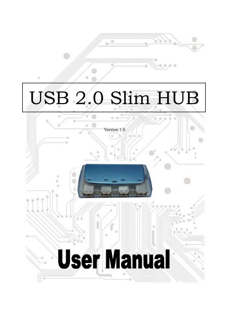
<strong>USB</strong> 2.0 Slim HUB<br />
Version 1.0
Contents<br />
1.0 Introduction ………..…………………………….P.2<br />
2.0 Features ……………….………………………….P.2<br />
3.0 Specification ………………………………………..P.2<br />
4.0 Installation …………...…………….………….…….P.3<br />
5.0 FCC Statement ……………..………….……….P.3<br />
1
1.0 Introduction<br />
<strong>USB</strong> 2.0 Slim HUB User's Manual<br />
This is designed in accordance to <strong>USB</strong> specification Rev 1.1/2.0 which act as a bridge<br />
between the main computer host and the down stream <strong>USB</strong> devices. It is able to complement<br />
PC serial interface by connecting a full range of peripherals, which is very simple and flexible<br />
for the users.<br />
There is one upstream port that connects to the PC host and there are four down steam ports<br />
connecting up to 127 <strong>USB</strong> devices in a tiered-star configuration. It supports both full speed<br />
(480M bps) and low speed (1.5M bps) devices which include keyboards, mice, scanner.<br />
It is also protected by automatic per-port over-current detection and recovery and the LED<br />
indicating the connection status and power source.<br />
2.0 Features<br />
• Full compliance with <strong>USB</strong> specification Rev. 1.1.<br />
• With one up-stream port and four down-stream ports.<br />
• Connects up to 127 devices in a tiered star configuration.<br />
• Supports both full-speed (12M bps) and low-speed (1.5M bps) devices.<br />
• Select between self-powered mode and bus-powered mode automatically.<br />
• Per port over current detection/protection and power switch control.<br />
• LED for bus-power, self-power and four down-stream connection status.<br />
3.0 Specifications<br />
-Upstream port 1<br />
-Downstream port 4<br />
-LED:<br />
4 for BUS Power status when device connect. The green light is<br />
power and red light is for <strong>USB</strong> 2.0 high speed.<br />
-Enclosure:<br />
Plastic<br />
-Per port Output current: 500mA<br />
-Operating temperature: 0 degrees to 40 degrees<br />
-Storage temperature: -20 degrees to 60 degrees<br />
-Humidity:<br />
0% ~ 80% RH<br />
-Power Adapter 1.5 A , 6 V , 2.0 mm , out “ – “ , inside “ + “<br />
2
4.0 Installation<br />
For Self power configuration, please start from No. 1; for BUS power configuration, please<br />
start from No. 2.<br />
1. Plug the DC plug into the DC jack and plug the AC adaptor into an electrical outlet.<br />
Please check the electrical out let has the same voltage as the hob adaptor.<br />
2. Plug Connector A into the <strong>USB</strong> port of host computer.<br />
3. Plug Connector B into the upstream port of the hub.<br />
4. Plug all the devices into downstream port of the hub.<br />
5. When the hub is connected to the computer, the LED lights will sparkle.<br />
5.0 FCC Statement<br />
This equipment has been tested and found to comply with the limits for a Class B digital<br />
device, pursuant to Part 15 of the FCC Rules. These limits are designed to provide reasonable<br />
protection against harmful interference when the equipment is operated in a residential<br />
installation. This equipment generates, uses, and can radiate radio frequency energy and if not<br />
installed and used in accordance with the instruction manual may cause harmful interference<br />
to radio communications. However, there is no guarantee that interference will not occur in a<br />
particular installation. If this equipment dose cause harmful interference to radio or television<br />
reception, which can be determined by turning the equipment off and on, the user is<br />
encouraged to try to correct the interference by one or more of the following measures:<br />
--Reorient or relocate the receiving antenna.<br />
--Increase the separation between the equipment and receiver.<br />
--Connect the equipment into and outlet on a circuit different from that to which the receiver<br />
is connected.<br />
--Consult the dealer or an experienced radio TV technician for help.<br />
Notices:<br />
1. The changes or modification not expressly approved by the party responsible for<br />
compliance could void the user’s authority to operate the equipment.<br />
2. Shielded interface cables and AC power cord, if any must be used in order to comply with<br />
the emission limits.<br />
3


