Operation_Manual_V2.pdf - Belimo Actuators (Shanghai)
Operation_Manual_V2.pdf - Belimo Actuators (Shanghai)
Operation_Manual_V2.pdf - Belimo Actuators (Shanghai)

You also want an ePaper? Increase the reach of your titles
YUMPU automatically turns print PDFs into web optimized ePapers that Google loves.
Room Control Module<br />
<strong>Operation</strong> <strong>Manual</strong><br />
Ver. 2<br />
<br />
<strong>Belimo</strong> Asia Pacific
<strong>Operation</strong><br />
<strong>Operation</strong><br />
<strong>Manual</strong><br />
<strong>Manual</strong><br />
Room<br />
Room<br />
Control<br />
Control<br />
Module<br />
Module<br />
LON<br />
VAV/CAV system solution<br />
with room control module and room unit<br />
<br />
Table of contents<br />
System overview 2<br />
Product technical information<br />
VAV-Compact 3-5<br />
T24-V42(-V02)BAC 6-8<br />
- Network variables for BACnet 9<br />
T24-V42(-V02)LON 10-12<br />
- Functional profile for LonWorks 13-14<br />
T24-MP 15-16<br />
TG-R10000 17<br />
Application description 18-29<br />
<strong>Operation</strong> and setting 30-35<br />
1
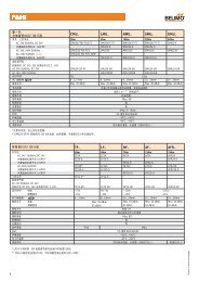
System Overview<br />
Overview of the system<br />
MP<br />
®<br />
BUS<br />
TECHNOLOGY BY BELIMO<br />
T24-MP<br />
<br />
VAV Compact<br />
*Max. of 2 VAV boxes<br />
connected together<br />
Control Module<br />
BACnet or LonWorks®<br />
Product overview<br />
Description<br />
LMV-D2-MFT-RM<br />
(LMV-D2-MP)<br />
NMV-D2-MP<br />
VAV Compact included with sensor, VAV controller and actuator functions<br />
VAV boxes<br />
VAV Boxes included with 4 x hangers, velocity sensor and clear labels,<br />
More prooduct ranges available for selection<br />
T24-V42(-V02)...<br />
Room Control Module with communcation protocol BACnet or LonWorks<br />
T24-MP<br />
(TG-R10000)<br />
Room Unit with LCD display and diagnostic socket for servicing device<br />
or Room Sensor used in open area<br />
Note:<br />
Detailed documentation for the VAV-Compact,<br />
T24-V42(-V02)..., T24-MP, TG-R10000,<br />
ZTH_VAV, tools and interfaces can be found<br />
on the Internet at www.belimo.com<br />
2
Technical datasheet<br />
VAV-Compact<br />
A pressure sensor, digital VAV controller<br />
and damper actuator all in one,<br />
providing a VAV-Compact solution with a<br />
communications capability for pressureindependent<br />
VAV and CAV systems in the<br />
comfort zone<br />
Control function: VAV-CAV / Open-Loop<br />
Control: DC 2...10 V / 0...10 V / MP-bus<br />
With additional connection facility for sensors<br />
or switches (not available for LMV-D2-MFT-RM)<br />
Specially integration into VAV Room Control<br />
Module T24-V42(-V02)... + T24-MP<br />
Service button and LEDs for servicing and<br />
commissioning<br />
Diagnostic socket for operating devices<br />
LMV-D2-MFT-RM<br />
(LMV-D2-MP)<br />
NMV-D2-MP<br />
Brief description Description<br />
Subject to technical change V3.1 01042010<br />
Application<br />
Pressure measurement<br />
Control function<br />
VAV – variable air volume<br />
CAV – constant air volume<br />
Bus function<br />
Test function / test display<br />
Operating and service devices<br />
Assembly and connection<br />
OEM factory settings<br />
Overviewof types<br />
The digital VAV-Compact has PI control characteristics and is used for pressure-independent<br />
control of VAV units in the comfort zone.<br />
Maintenance-free, dynamic, differential pressure sensor technology, proven in a wide range of<br />
applications, suitable for use in offices, hospital wards, alpine hotels or cruise liners.<br />
VAV-CAV or open-loop operation (actuator/volumetric flow sensor) for integration in an external<br />
VAV control circuit; Feedback of damper position for fan optimisation<br />
For variable air volume applications based on a modulating reference variable, e.g. supplied by a<br />
room temperature controller or a DDC or bus system. It facilitates demand-related, power-saving<br />
ventilation in individual rooms or in zones of air conditioning systems. The V’min ... V’max working<br />
range can be subdivided by selecting a mode. The following operating modes are available:<br />
DC 2...10 V / 0...10 V / adjustable / bus.<br />
For constant air volume applications, e.g. in step mode, controlled by means of a switch. The<br />
following operating modes are available: CLOSE / Vmin / Vmid / Vmax / OPEN<br />
Upto eight <strong>Belimo</strong> MP devices (VAV / damper actuator / valve) can be connected together over<br />
the MP-Bus and integrated into the following systems:<br />
– LONWORKS® applications with <strong>Belimo</strong> UK24LON interface<br />
– Communication functions with <strong>Belimo</strong> T24-V42(-V02)... + T24-MP<br />
– DDC controller with integrated MP-Bus protocol<br />
– Fan optimiser applications with optimisation COU24-A-MP<br />
A sensor (0...10 V or passive, e.g. a temperature sensor) or a switch can optionally be integrated<br />
into the higher-level DDC or bus system via the MP-Bus.<br />
The VAV-Compact features an LED with a ready display for commissioning and functional checking<br />
as well as a service mode with air shortage, excess air and setpoint = actual value display<br />
with LEDs.<br />
<strong>Belimo</strong> PC-Tool, remote control or ZTH-VAV, plugged into the VAV-Compact Via MP-Bus<br />
The VAV-Compact, which is assembled on the unit by the OEM, is connected using the prefabricated<br />
connecting cable.<br />
The VAV-Compact is mounted on the VAV unit by the unit manufacturer, who adjusts and tests it<br />
according to the application. The VAV-Compact is sold exclusively via the OEM channel for this<br />
reason.<br />
* Type LMV-D2-MFT-RM, same as the LMV-D2-MP in function but without a position indicator and<br />
additional connection facility for sensors or switches<br />
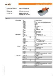
Type Torque Power consumption For wire sizing Weight<br />
LMV-D2-MFT-RM 5 Nm 3 W 5VA (max. 5 A @ 5 ms) approx. 500 g<br />
(LMV-D2-MP)<br />
NMV-D2-MP 10 Nm 3.5 W 5.5VA (max. 5 A @ 5 ms) approx. 700 g<br />
3
Technical datasheet<br />
VAV-Compact<br />
Technical data<br />
Supply<br />
Nominal voltage<br />
Power supply range<br />
Differential pressure sensor<br />
Operating pressure<br />
Characterising<br />
Installation position<br />
Operating medium (see «Materials»)<br />
Materials<br />
Measuring air conditions<br />
Control function<br />
VAV and CAV applications<br />
Operating volumetric flow<br />
.<br />
Vnom<br />
.<br />
Vmax<br />
.<br />
Vmin .<br />
Vmid<br />
Classic control<br />
Mode for reference value input w<br />
(connection 3)<br />
Mode for actual volumetric flow signal U5<br />
(connection 5)<br />
AC 24 V, 50 / 60 Hz<br />
DC 24 V<br />
AC 19.2 ... 28.8 V<br />
DC 21.6 ... 28.8 V<br />
2 ... 300 Pa (OEM-specific)<br />
max. 1000 Pa<br />
OEM-specific Differential pressure sensor Linearisation<br />
Any, no reset necessary<br />
Supply and exhaust air in the comfort zone and in applications with sensor compatible media<br />
PC + ABS to UL94-V0; stainless steel, DIN 1.4301 X 10CrNiS1810; PP Santoprene<br />
0... +50ºC / 5... 95% r.h., non-condensing<br />
– VAV-CAV<br />
– Open-loop operation<br />
– Supply/exhaust air units in stand-alone operation / master-slave / parallel connection for<br />
rooms with positive/negative pressure or neutral air pressure<br />
– Mixing units<br />
OEM-specific nominal .<br />
volumetric flow setting, matches VAV box<br />
30 ... 100% of Vnom<br />
.<br />
0 ... 100% of V<br />
. nom<br />
.<br />
0 ... 100% of ( V min... Vmax)<br />
– DC 2... 10 V / (4... 20 mA with 500 resistance)<br />
– DC 0... 10 V / (0... 20 mA with 500 resistance)<br />
– Adjustable DC 0... 10 V<br />
– DC 2... 10 V<br />
– DC 0... 10 V } max. 0.5 mA<br />
– Adjustable<br />
.<br />
DC 0... 10 V<br />
. .<br />
Input resistance min. 100 k<br />
Operating modes for constant air volume CLOSE / Vmin / Vmid*/ V max / OPEN * (* only with AC 24 V supply)<br />
Communication control<br />
Addressin busoperation<br />
MP1... 8 (classic control: PP)<br />
DDC controllor<br />
DDC controller / PLC, from various manufacturers, with integrated MP interface<br />
Fan optimiser<br />
Sensor integration<br />
With BELIMO optimiser COU24-A-MP<br />
Passive (Pt1000, Ni1000 etc) and active sensors (0...10 V) e.g. temperature, humidity<br />
(not available for LMV-D2-MFT-RM)<br />
2-point signal (switching capacity 16mA @ 24 V), e.g. switches, occupancy switches<br />
Communication (BACnet or LonWork) With BELIMO T24-V42(-V02)... + T24-MP<br />
Only MP2 or 3 addressing available<br />
<strong>Operation</strong> and servicing<br />
Pluggable / PC-Tool (V3.1 or higher) / ZTH-VAV hand-operated device<br />
Communication<br />
PP / MP-Bus, max. DC 15V, 1200 baud<br />
Button<br />
Adaptation / addressing / service function<br />
LED indicator<br />
– 24 V feed<br />
– Status / service / bus function<br />
Actuator<br />
Brushless, non-blocking actuator with current reduction<br />
Direction of rotation<br />
ccw / cw<br />
Adaptation<br />
<strong>Manual</strong> disengagement<br />
Setting range recording and resolution to control range<br />
Push button, self-resetting without affecting functions<br />
Sound power level<br />
max. 35dB<br />
Angle of rotation 95° , with adjustable, mechanical or electronic limiting<br />
Position indication<br />
Mechanical with pointer (not available for LMV-D2-MFT-RM)<br />
Spindle driver<br />
– Clamp, for round spindles 10... 20 mm / square spindles 8... 16 mm<br />
– Positive fit, wide range of versions, e.g. 8 x 8 mm<br />
Connection<br />
Cable, 4 x 0.75 mm 2 , terminals<br />
Safety<br />
Protection class<br />
III Safety extra-low voltage<br />
Degree of protection<br />
EMC<br />
Mode of operation<br />
IP 54<br />
CE according to 89/336/EEC<br />
Type 1 (to EN 60730-1)<br />
}<br />
4
Technical datasheet<br />
VAV-Compact<br />
Technical data<br />
Safety<br />
Rated impulse voltage<br />
Control pollution degree<br />
Ambient conditions<br />
Non-operating temperature<br />
Ambient humidity range<br />
Maintenance<br />
(continued)<br />
0.5 kV (to EN 60730-1)<br />
2 (to EN 60730-1)<br />
0 ... +50°C<br />
–20 ... +80°C<br />
5...95% r.h., non-condensating (to EN 60730-1)<br />
Maintenance-free<br />
Dimensions [mm]<br />
LMV-D2-MFT-RM (LMV-D2-MP)<br />
NMV-D2-MP<br />
<br />
<br />
<br />
<br />
<br />
<br />
<br />
<br />
<br />
<br />
Tool connection 1<br />
Local connection via the service socket<br />
on the MP actuator with ZK1-GEN cable<br />
USB<br />
BELIMO<br />
PC-Tool<br />
USB 2.0 cable<br />
with A to B plug<br />
RJ11 (4/6)<br />
ZK1-GEN<br />
USB<br />
24 V<br />
GND<br />
2<br />
1<br />
Note<br />
The mode switch must be set to “MA” (master).<br />
Tool connection 2<br />
Local connection via the service socket<br />
on the MP actuator with ZK2-GEN cable<br />
USB<br />
BELIMO<br />
PC-Tool<br />
USB 2.0 cable<br />
with A to B plug<br />
RJ11 (4/6)<br />
ZK2-GEN<br />
MP<br />
AC 24 V<br />
_<br />
+ DC 24 V<br />
~ T<br />
white = GND<br />
GND<br />
green = MP<br />
blue not connected<br />
USB<br />
1<br />
2<br />
5<br />
Note<br />
The mode switch must be set to “MA” (master).<br />
LMV-D2-MFT-RM<br />
(LMV-D2-MP)<br />
NMV-D2-MP<br />
T<br />
_<br />
~<br />
+<br />
U5 / MP<br />
For more detailed informaiton, please refer to tool connection guilde.<br />
5
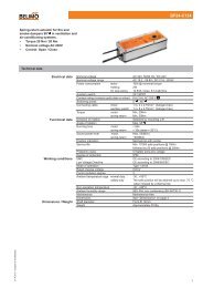
T24-V42(-V02)BAC<br />
Room Control Module BACnet<br />
Product overview<br />
The T24-V42(-V02)BAC room control module is<br />
specifically designed for VAV applications with<br />
direct link to BACnet® network.<br />
Features<br />
On-board LED indication without cover removal<br />
Built-in room control applications<br />
PI control algorithm<br />
Operating modes: Normal, Economy and Standby<br />
Minimum setpoint limitation<br />
Memory storage<br />
Brief description<br />
The T24-V42(-V02)BAC room control module offers the advantages of network control via BACnet® Master-Slave/Token-Passing<br />
(MS/TP) protocol. This controller features memory storage, analogue input, digital input, analogue output, 3 x AC 24V digital outputs,<br />
MP-Bus interface for connection to the <strong>Belimo</strong> VAV Compact and optional T24-MP room unit or TG-R10000 room sensor.<br />
Suitable for new or existing VAV system installations.<br />
The T24-V42(-V02)BAC room control module conforms to the BACnet® MS/TP protocol for open communication and interoperability<br />
with third party BACnet® devices, providing greater freedom in system design.<br />
Technical data<br />
Subject to technical change V2-.1 01042010<br />
Nominal voltage<br />
AC 24 V 50/60 Hz<br />
Power supply range<br />
AC 19.2...28.8 V<br />
Wiring terminals<br />
2<br />
Screw terminals, 0.5...2.5mm<br />
Power consumption:<br />
T24-V42BAC 6.0 VA @ AC 24V, 50/60 Hz<br />
T24-V02BAC 3.5 VA @ AC 24V, 50/60 Hz<br />
Communication - BACnet®<br />
Master-Slave/Token-Passing (MS/TP) protocol<br />
Functional profile<br />
BACnet Application Specific Controller (B-ASC)<br />
Firmware<br />
Native BACnet® firmware<br />
Band rate<br />
9,600, 19,200, 38,400 (default) or 76,800bps<br />
Network address<br />
Max. can support up to 0x7F (default = 0x7F)<br />
Device address Max. can support up to 0x3F FF FF (default = 0x00 00 00)<br />
Conductors, cables<br />
22 AWG standard, 3-wire twisted, Shielded cable<br />
Cable length in accordance with BACnet® bus standard<br />
Communication - MP<br />
Standard <strong>Belimo</strong> MP connection<br />
Input / output control<br />
Analog input x 1 (Type NTC, 10kOhm@25 °C, sensing range 0...40 °C)<br />
(AO, DO only available for T24-V42BAC)<br />
Analog output x 1 (2...10 V, max. 5mA)<br />
Digital input x 1 (Dry contact, max. 10mA)<br />
Digital output x 3 (AC 24V, SELV, max. 1A)<br />
Application selection<br />
Application number selectable via T24-MP room sensor; can be<br />
overridden by BMS<br />
LED indications<br />
- Power<br />
- Digital output 1 ~ 3 (Only for T24-V42BAC)<br />
- BACnet® communication status<br />
Protection class<br />
III Safety extra-low voltage<br />
Degree of protection<br />
IP20<br />
Low-voltage directive<br />
CE according to 2006/95/EC<br />
EMC directive<br />
CE according to 2004/108/EC<br />
Ambient conditions 0...+50 °C<br />
Non-operating temperature -10...+60 °C<br />
Ambient humidity range<br />
5...95% r.h., non-condensing<br />
Weight:<br />
Dimensions (L x W x H)<br />
Mounting<br />
T24-V42BAC<br />
T24-V02BAC<br />
250 g<br />
230 g<br />
130 x 106 x 49.2 mm<br />
2 x Screws provided or DIN rail 35mm<br />
To be opened by accredited servicing agents only<br />
Electronic control - Type 2.B action (micro-disconnection operation)<br />
Separate collection for electrical and electronic equipment<br />
6
T24-V42(-V02)BAC<br />
Room Control Module BACnet<br />
Application number selection<br />
%<br />
Heating<br />
Cooling<br />
100<br />
Vmax<br />
Vmin<br />
T [ 0 C]<br />
W<br />
Heat mode<br />
#20: Heat or Cool Econ mode<br />
%<br />
El. 1<br />
Cooling<br />
100<br />
Vmax<br />
Fan<br />
No. 10 Cool Only No. 51 Cool + parallel fan<br />
3-point reheat with deadband<br />
1K reheat switching differential<br />
No. 20 Heat (or Cool) ** No. 61 Cool + parallel fan<br />
Modulating reheat with deadband<br />
1K reheat switching differential<br />
No. 30 Cool<br />
No. 12* Cool Only + series fan<br />
Electric reheat 1 stage with deadband<br />
1K reheat switching differential<br />
No. 40 Cool<br />
No. 22* Heat (or Cool) + series fan **<br />
Electric reheat 2 stages with deadband<br />
1K reheat switch differential<br />
No. 50 Cool<br />
3-point reheat with deadband<br />
No. 32* Cool + series fan<br />
Electric reheat 1 stage with deadband<br />
No. 60<br />
No. 21<br />
Cool<br />
Modulating reheat with deadband<br />
Cool + parallel fan<br />
with deadband<br />
No. 42*<br />
No. 52*<br />
1K reheat switching differential<br />
Cool + series fan<br />
Electric reheat 2 stages with deadband<br />
1K reheat switching differential<br />
Cool + series fan<br />
3-point reheat with deadband<br />
1K<br />
DB<br />
W<br />
#31:<br />
Cool + Parallel fan + 1-stage El. reheat<br />
Vmin<br />
T [ 0 C]<br />
reheat & fan<br />
Econ mode<br />
No. 31<br />
No. 41<br />
Cool + parallel fan<br />
Electric reheat 1 stage with deadband<br />
1K reheat switching differential<br />
Cool + parallel fan<br />
Electric reheat 2 stages with deadband<br />
1K reheat switching differential<br />
No. 62*<br />
Cool + series fan<br />
Modulating reheat with deadband<br />
* Series fan will always ON<br />
** Factory setting = Heat<br />
xxx<br />
T24-V02BAC functions under in Application 10 & 20<br />
The above room control applications are pre-stored in the T24-V42(-V02)BAC room control module. Application number can be<br />
selected via the T24-MP room unit through MP-BUS commands or by communication network BACnet. (Factory setting = 10)<br />
Detailed information can be found in operation manual.<br />
Status output by room control module<br />
If the T24-V42(-V02)BAC room control module communicates with the building management system (BMS) via BACnet®<br />
protocol then the following status information or reset values will include:<br />
Heating / cooling mode status<br />
Heating / cooling setpoint<br />
Operating mode<br />
- Normal<br />
- Standby<br />
- Override<br />
- Economy<br />
Room temperature value<br />
Temperature setpoint<br />
Fan status<br />
Heater status<br />
Air flow value in CFM<br />
Damper position in %<br />
T24-MP<br />
VAV Compact<br />
*Max. of 2 VAV boxes<br />
connected together<br />
Control Module<br />
BACnet®<br />
To be opened by accredited servicing agents only<br />
Electronic control - Type 2.B action (micro-disconnection operation)<br />
Separate collection for electrical and electronic equipment<br />
7
T24-V42(-V02)BAC<br />
Room Control Module BACnet<br />
Wiring diagram<br />
Electrical heaters,<br />
parallel/series fan<br />
(3 x DO)<br />
AC 24V<br />
Power<br />
supply<br />
MP-Bus (MP1~3)<br />
M<br />
Heater<br />
1<br />
Heater<br />
2<br />
Fan<br />
1A fuse<br />
AC 24V<br />
~ <br />
1 A<br />
1 2 3 5<br />
3-point<br />
reheat<br />
valve<br />
Com DO1 Com DO2 Com<br />
DO3<br />
*Relay<br />
supplied<br />
by others<br />
AC 24V<br />
Caution: live voltage<br />
1 2 5<br />
1 2 3 5<br />
VAV Compact<br />
24V<br />
Com MP1 MP2 MP3<br />
ac<br />
VAV Compact<br />
1 2 3<br />
AO Com AI<br />
Com DI Com<br />
D+<br />
D-<br />
Com SHLD<br />
Power DO1 DO2 DO3 Signal<br />
MP<br />
BUS <br />
To<br />
From<br />
MS/TP<br />
Next Device Last Device<br />
BACnet®<br />
Software<br />
reflash<br />
System<br />
reset<br />
Input & output assignment<br />
Inputs<br />
Analogue<br />
output (AO)<br />
2-10Vdc<br />
External<br />
sensor (AI)<br />
NTC 10k<br />
Digital input<br />
(DI)<br />
BACnet<br />
- AI External temp. sensor TG-R10000 *<br />
- DI Remote setpoint shift, e.g. Occupancy sensor *<br />
Open - Normal mode, Close - Economy mode<br />
xxx<br />
M<br />
*Power<br />
supply<br />
* Optional Outputs<br />
External<br />
sensor<br />
NTC 10k<br />
(TG-R10000)<br />
Only available for T24-V42BAC<br />
Occupancy<br />
sensor<br />
System<br />
reset<br />
- AO Modulating reheat control DC 2...10V<br />
- DO1 Heating output I AC 24V ON/OFF<br />
- DO2 Heating output II AC 24V ON/OFF<br />
- DO3 Parallel or series fan output AC 24V ON/OFF<br />
Dimensions [mm]<br />
49.2<br />
106<br />
To be opened by accredited servicing agents only<br />
Electronic control - Type 2.B action (micro-disconnection operation)<br />
Separate collection for electrical and electronic equipment<br />
8
T24-V42(-V02)BAC<br />
Network Variables<br />
Functional profile according to BACnet®<br />
The T24-V42(-V02)BACnet room control module is certified by BACnet Testing LAboratories (BTL). The module functions are supplied<br />
with the BACnet® network as standardised network variables according to BACnet Application Specific Controller (B-ASC).<br />
Network variable<br />
Type<br />
Instance<br />
Number<br />
Read / Write<br />
Availability on<br />
V02 or V42 Setting range / selection Description<br />
Rm_Temp AI 0 R V02 & V42 5.0~40.0 ºC, step 0.1 ºC Current room temperature<br />
0: Normal<br />
Eco_Mode BI 0 R V02 & V42<br />
1: Economy Economy / normal mode status<br />
Rm_Setpt AV 0 R/W V02 & V42 10.0~30.0 ºC, step 0.5 ºC Room temperature setpoint<br />
Minimum setpoint limitation in Normal<br />
Min_Setpt AV 1 R/W V02 & V42 10.0~30.0 ºC, step 0.5 ºC<br />
mode<br />
Eco_Cool_Setpt AV 2 R/W V02 & V42 20.0~30.0 ºC, step 0.5 ºC Setpoint of cooling in Economy mode<br />
Eco_Heat_Setpt AV 3 R/W V02 & V42 10.0~20.0 ºC, step 0.5 ºC Setpoint of heating in Economy mode<br />
Cool_P_Band AV 4 R/W V02 & V42 1~3 K, step 1 K P-band in cooling mode<br />
Heat_P_Band AV 5 R/W V02 & V42 1~3 K, step 1 K P-band in heating mode<br />
Deadband AV 6 R/W V02 & V42 0.5, 1.0, 2.0 K Deadband<br />
Int_Time AV 7 R/W V02 & V42 60~300 sec, step 30 sec Integral action time<br />
3Pt_Float_Time AV 8 R/W V42 60~150 sec, step 10 sec 3-point float control time for reheat valve<br />
App_No AV 9 R/W V02 & V42 10~62 Application number<br />
Manu_Override AV 10 R/W V02 & V42 0: Auto, 1: Fully Open, 2: Fully Close <strong>Manual</strong> override functions by BMS<br />
Mod_Reheat AV 11 R V42 0-100% Modulating signal (2-10V) output in %<br />
Act1_Damper_Pos AV 12 R V02 & V42 0-100% Damper position of 1 st actuator<br />
Act2_Damper_Pos AV 13 R V02 & V42 0-100% Damper position of 2 nd actuator<br />
Act1_Vmax AV 14 R/W V02 & V42 0~9999CFM V'max setting value of 1 st actuator<br />
Act1_Vmin AV 15 R/W V02 & V42 0~9999CFM V'min setting value of 1 st actuator<br />
Act1_flow AV 16 R V02 & V42 0~9999CFM Actual flow rate of 1 st actuator<br />
Act2_Vmax AV 17 R/W V02 & V42 0~9999CFM V'max setting value of 2 nd actuator<br />
Act2_Vmin AV 18 R/W V02 & V42 0~9999CFM V'min setting value of 2 nd actuator<br />
Act2_flow AV 19 R V02 & V42 0~9999CFM Actual flow rate of 2 nd actuator<br />
Act1_Output_St AV 20 R V02 & V42<br />
0 (Normal VAV Compact)<br />
1 (VAV Compact don't exist)<br />
2 (Invalid VAV Compact)<br />
8 (Room unit in Service Mode) Warning signal of 1 st actuator<br />
Act2_Output_St AV 21 R V02 & V42<br />
0 (Normal VAV Compact)<br />
1 (VAV Compact don't exist)<br />
2 (Invalid VAV Compact)<br />
8 (Room unit in Service Mode) Warning signal of 2 nd actuator<br />
Display_Set BV 0 R/W V02 & V42<br />
0: Room temp. & setpoint display<br />
1: Setpoint display only LCD display in room unit<br />
Rm_Unit_Overid BV 1 R/W V02 & V42<br />
0: Disable/<br />
1: Enable<br />
Room unit to override the<br />
Standby mode ordered by BMS<br />
Heat_Cool_ChOv BV 2 R/W V02 & V42<br />
0: Cool/<br />
1: Heat<br />
Heating / cooling mode changeover<br />
(only apply for application 20 & 22)<br />
Module_Mode BV 3 R/W V02 & V42<br />
0: Standby/<br />
1: Normal<br />
BMS request<br />
Standby / Normal<br />
Heater1_State BV 4 R V42<br />
0: Off<br />
1: On Heater1 status<br />
Heater2_State BV 5 R V42<br />
0: Off<br />
1: On Heater2 status<br />
Fan_State BV 6 R V42<br />
0: Off<br />
1: On Fan status<br />
Rm_Unit_State BV 7 R V02 & V42<br />
0: Standby<br />
1: Normal Room Unit status<br />
Override_State BV 8 R V02 & V42<br />
0: Room unit in Standby mode<br />
1: Room unit in Override enable<br />
Room unit to override the Standby mode<br />
ordered by BMS (1 to 12 hrs override<br />
mode to normal setpoint operation)<br />
Note: * The LCD will display "Err" message when using invalid actuator series<br />
V02 = T24-V02BAC, V42 = T24-V42BAC<br />
9
T24-V42(-V02)LON<br />
Room Control Module LON<br />
Product overview<br />
The T24-V42(-V02)LON room control module is<br />
specifically designed for VAV applications with<br />
direct link to LonWorks® network.<br />
Features<br />
On-board LED indication without cover removal<br />
Built-in room control applications<br />
PI control algorithm<br />
Operating modes: Normal, Economy and Standby<br />
Minimum setpoint limitation<br />
<br />
Brief description<br />
The T24-V42(-V02)LON room control module offers the advantages of network control via the high performance LON transceiver.<br />
This controller features memory storage, analogue input, digital input, analogue output, 3 x AC 24V digital outputs, MP-Bus<br />
interface for connection to the <strong>Belimo</strong> VAV Compact and optional T24-MP room unit or TG-R10000 room sensor. Suitable for new<br />
or existing VAV system installations.<br />
The T24-V42(-V02)LON room control module conforms to the LonMark® communication protocol for open communication and<br />
interoperability with third party LonMark® devices, providing greater freedom in system design.<br />
Technical data<br />
Subject to technical change V6.1 01042010<br />
Nominal voltage<br />
AC 24 V 50/60 Hz<br />
Power supply range<br />
AC 19.2...28.8 V<br />
Wiring terminals<br />
2<br />
Screw terminals, 0.5...2.5mm<br />
Power consumption:<br />
T24-V42LON 6.0 VA @ AC 24V, 50/60 Hz<br />
T24-V02LON 3.5 VA @ AC 24V, 50/60 Hz<br />
Communication - LON<br />
LonTalk® protocol<br />
Functional profile According to LonMark® / SFPTvariableAirVolume object #8010<br />
Processor / Memory<br />
Neuron 3150® ; 10 MHz ; 64kb flash memory input/output control<br />
Transceiver<br />
Echelon® , Free topology transceiver (FT-X1)<br />
Media channel<br />
TP/FT-10; 78 kbps<br />
Service button and status LED<br />
According to LonMark® guidelines<br />
Conductors, cables<br />
Conductor lengths, cable specifications and topology of the LonWorks®<br />
network according to Echelon® directives<br />
Communication - MP<br />
Standard <strong>Belimo</strong> MP connection<br />
Input / output control<br />
Analog input x 1 (Type NTC, 10kOhm@25 °C, sensing range 0...40 °C)<br />
(AO, DO not available for T24-V02LON)<br />
Analog output x 1 (2...10 V, max. 5mA)<br />
Digital input x 1 (Dry contact, max. 10mA)<br />
Digital output x 3 (AC 24V, SELV, max. 1A)<br />
Application selection<br />
Application number selectable via T24-MP room sensor; can be<br />
overridden by BMS<br />
LED indications<br />
- Power<br />
- Digital output 1 ~ 3 (Only for T24-V42LON)<br />
- LonWorks® communication status<br />
Protection class<br />
III Safety extra-low voltage<br />
Degree of protection<br />
IP20<br />
Low-voltage directive<br />
CE according to 2006/95/EC<br />
EMC directive<br />
CE according to 2004/108/EC<br />
Ambient conditions 0...+50 °C<br />
Non-operating temperature -10...+60 °C<br />
Ambient humidity range<br />
5...95% r.h., non-condensing<br />
Weight:<br />
Dimensions (L x W x H)<br />
Mounting<br />
T24-V42LON<br />
T24-V02LON<br />
250 g<br />
230 g<br />
130 x 106 x 49.2 mm<br />
2 x Screws provided or DIN rail 35mm<br />
To be opened by accredited servicing agents only<br />
Electronic control - Type 2.B action (micro-disconnection operation)<br />
Separate collection for electrical and electronic equipment<br />
10
T24-V42(-V02)LON<br />
Room Control Module LON<br />
Application number selection<br />
%<br />
Heating<br />
Cooling<br />
100<br />
Vmax<br />
Vmin<br />
T [ 0 C]<br />
W<br />
Heat mode<br />
#20: Heat or Cool Econ mode<br />
%<br />
El. 1<br />
Cooling<br />
100<br />
Vmax<br />
Fan<br />
No. 10 Cool Only No. 51 Cool + parallel fan<br />
3-point reheat with deadband<br />
1K reheat switching differential<br />
No. 20 Heat (or Cool) ** No. 61 Cool + parallel fan<br />
Modulating reheat with deadband<br />
1K reheat switching differential<br />
No. 30 Cool<br />
No. 12* Cool Only + series fan<br />
Electric reheat 1 stage with deadband<br />
1K reheat switching differential<br />
No. 40 Cool<br />
No. 22* Heat (or Cool) + series fan **<br />
Electric reheat 2 stages with deadband<br />
1K reheat switch differential<br />
No. 50 Cool<br />
3-point reheat with deadband<br />
No. 32* Cool + series fan<br />
Electric reheat 1 stage with deadband<br />
No. 60<br />
No. 21<br />
Cool<br />
Modulating reheat with deadband<br />
Cool + parallel fan<br />
with deadband<br />
No. 42*<br />
No. 52*<br />
1K reheat switching differential<br />
Cool + series fan<br />
Electric reheat 2 stages with deadband<br />
1K reheat switching differential<br />
Cool + series fan<br />
3-point reheat with deadband<br />
1K<br />
DB<br />
W<br />
#31:<br />
Cool + Parallel fan + 1-stage El. reheat<br />
Vmin<br />
T [ 0 C]<br />
reheat & fan<br />
Econ mode<br />
No. 31<br />
No. 41<br />
Cool + parallel fan<br />
Electric reheat 1 stage with deadband<br />
1K reheat switching differential<br />
Cool + parallel fan<br />
Electric reheat 2 stages with deadband<br />
1K reheat switching differential<br />
No. 62*<br />
Cool + series fan<br />
Modulating reheat with deadband<br />
* Series fan will always ON<br />
** Factory setting = Heat<br />
xxx<br />
T24-V02LON functions under in Application 10 & 20<br />
The above room control applications are pre-stored in the T24-V42(-V02)LON room control module. Application number can be<br />
selected via the T24-MP room unit through MP-Bus commands or by communication network LonWorks. (Factory setting = 10)<br />
Detailed information can be found in operation manual.<br />
Status output by room control module<br />
If the T24-V42(-V02)LON room control module communicates with the building management system (BMS) via LonTalk®<br />
protocol then the following status information or reset values will include:<br />
Heating / cooling mode status<br />
Heating / cooling setpoint<br />
Operating mode<br />
- Normal<br />
- Standby<br />
- Override<br />
- Economy<br />
Room temperature value<br />
Temperature setpoint<br />
Fan status<br />
Heater status<br />
Air flow value in CFM<br />
Damper position in %<br />
T24-MP<br />
VAV Compact<br />
*Max. of 2 VAV boxes<br />
connected together<br />
Control Module<br />
LonWorks®<br />
To be opened by accredited servicing agents only<br />
Electronic control - Type 2.B action (micro-disconnection operation)<br />
Separate collection for electrical and electronic equipment<br />
11
T24-V42(-V02)LON<br />
Room Control Module LON<br />
Wiring diagram<br />
External<br />
sensor (AI)<br />
NTC 10k<br />
Analogue<br />
output (AO)<br />
2-10Vdc<br />
AC 24V<br />
Power<br />
supply<br />
MP-Bus (MP1~3)<br />
LonWorks<br />
(TG-R10000)<br />
External<br />
sensor<br />
NTC 10k<br />
*Power<br />
supply<br />
M<br />
Modulating<br />
reheat valve<br />
T24-MP<br />
1 2 5<br />
1A fuse<br />
AC 24V<br />
~ <br />
1 A<br />
1 2 3 5<br />
1 2 3 5<br />
VAV Compact<br />
VAV Compact<br />
LonWorks®<br />
AI<br />
Com<br />
AO<br />
Com<br />
24V<br />
Com MP1 MP2 MP3<br />
ac<br />
LON LON<br />
A B<br />
DI<br />
Com<br />
DO1 Com DO2 Com DO3 Com<br />
1 2 3<br />
AC 24V<br />
Power DO1 DO2 DO3 Signal<br />
MP<br />
BUS <br />
Occupancy<br />
sensor<br />
M<br />
*Relay supplied<br />
by others<br />
3-point<br />
reheat<br />
valve<br />
Caution: live voltage<br />
Digital input<br />
(DI)<br />
Input & output assignment<br />
Inputs<br />
Electrical heaters,<br />
parallel/series fan<br />
(3 x DO)<br />
System<br />
reset<br />
LonWorks<br />
service pin<br />
- AI External temp. sensor TG-R10000 *<br />
- DI Remote setpoint shift, e.g. Occupancy sensor *<br />
Open - Normal mode, Close - Economy mode<br />
xxx<br />
* Optional Outputs<br />
Heater<br />
1<br />
Only available for T24-V42LON<br />
Heater<br />
2<br />
Fan<br />
System<br />
reset<br />
LonWorks<br />
service pin<br />
- AO Modulating reheat control DC 2...10V<br />
- DO1 Heating output I AC 24V ON/OFF<br />
- DO2 Heating output II AC 24V ON/OFF<br />
- DO3 Parallel or series fan output AC 24V ON/OFF<br />
Dimensions [mm]<br />
49.2<br />
106<br />
To be opened by accredited servicing agents only<br />
Electronic control - Type 2.B action (micro-disconnection operation)<br />
Separate collection for electrical and electronic equipment<br />
12
T24-V42(-V02)LON<br />
Network Variables<br />
Functional profile according to LonMark®<br />
The T24-V42(-V02)LON room control module is certified by LonMark®. The module functions are supplied with the LonWorks®<br />
network as standardised network variables according to LonMark®. (Functional profile: SFPTvariableAirVolume object #8010)<br />
Input variables<br />
Input network<br />
variable<br />
Network variable<br />
type<br />
Setting range / selection Description Factory setting<br />
nvi3PtFloatTime SNVT_time_sec 60...150 (sec.), step 10 3 point floating control for reheat valve 90 sec.<br />
nviActOpenClose<br />
SNVT_hvac_overid HVO_OPEN,100.000,0<br />
HVO_CLOSE,-100.000,0<br />
HVO_NUL,0.000,0<br />
HVO_OPEN: Set actuator to fully open<br />
HVO_CLOSE: Set actuator to fully close<br />
HVO_NUL: Release command to auto<br />
nviApplication SNVT_count 10,20,30,40,50,60,21,31,41,51,61,12,22,32, Selection of application number 10<br />
42,52,62<br />
HVO_NUL,0.000,0<br />
nviApplicMode SNVT_hvac_mode HVAC_HEAT, HVAC_COOL Heating / cooling changeover HVAC_COOL<br />
nviCoolPband SNVT_temp_p 1…3 (K), step 1 P-band in cooling mode 1 K<br />
nviDeadband SNVT_temp_p 0.5,1.0,2.0 (K) Deadband range 1 K<br />
nviDisplaySetPt SNVT_switch Room temp. & setpoint display: 0.0 0<br />
Only setpoint display: 100.0 1<br />
Selection of LCD display by room unit 0.0 0<br />
nviEconCoolSetPt SNVT_temp_p 20.0…30.0 (°C), step 0.5 Setpoint of cooling in Economy mode 28 °C<br />
nviEconHeatSetPt SNVT_temp_p 10.0…20.0 (°C), step 0.5 Setpoint of heating in Economy mode 18 °C<br />
nviHeatPband SNVT_temp_p 1…3 (K), step 1 P-band in heating mode 2 K<br />
nviIntegralTime SNVT_time_sec 60…300 (sec.), step 30 Integral action time 120 sec.<br />
nviMinSetpoint SNVT_temp_p 10.0…30.0 (°C), step 0.5 Minimum setpoint limitation in Normal mode 10 °C<br />
nviOveridEnable SNVT_switch Room unit override enable: 100.0 1<br />
Room unit override disable: 0.0 0<br />
Enable / disable the room unit to override<br />
the Standby mode ordered by BMS (user<br />
can extend the operation in Normal mode)<br />
nviSetPoint SNVT_temp_p 10.0…30.0 (°C), step 0.5 Effective room temp. setpoint 24 °C<br />
nviSpaceTemp SNVT_temp_p 5...40 (°C) = current temperature value Value of current room temp. reading (no<br />
setting, display only)<br />
nviStandby SNVT_switch Standby mode: 100.0 1<br />
Normal mode: 0.0 0<br />
"Bold italic fonts" no actions for T24-V02LON<br />
100.0 1<br />
Standby / Normal mode selection 0.0 0<br />
-<br />
Explanation of special network variables:<br />
nviOveridEnable, nviStandby, nvoDisplySetPt, nvoEnergyHoldOff, nvoOveridEnable, nvoRmUnitOverid, nvoStandby<br />
belong to SNVT_switch network variable type. This type of network variable is composed of a percentage and a boolean state:<br />
Percentage<br />
0.0 0 100.0 1<br />
State<br />
Percentage<br />
State<br />
- In our application here, only the Boolean state is effective. The percentage can be ignored.<br />
nvoUnitStatus & nvoUnitStatus2 belongs to SNVT_hvac_status network variable type. It is expressed in the form of<br />
“mode, heat_output_primary, heat_output_secondary, cool_output, econ_output, fan_output, in_alarm”.<br />
Example: HVAC_AUTO, 0.000, 0.000, 100.000, 0.000, 100.000, 0<br />
Heat 1 = 0% Heat 2 = 0% Cool = 100% Fan = 100% Alarm = 1<br />
13
T24-V42(-V02)LON<br />
Network Variables<br />
Functional profile according to LonMark®<br />
The T24-V42(-V02)LON room control module is certified by LonMark®. The module functions are supplied with the LonWorks®<br />
network as standardised network variables according to LonMark®. (Functional profile: SFPTvariableAirVolume object #8010)<br />
Output variables<br />
Output network<br />
variable<br />
Network variable type Status Description<br />
nvo3PtFloatTime SNVT_time_sec 60…150 (sec.), step 10 3 point floating control for reheat valve<br />
nvoAct1Vflow SNVT_flow 0...9999 (CFM) Actual flow rate of 1st actuator<br />
nvoAct1Vmax SNVT_flow 0...9999 (CFM)<br />
V'max setting valve of 1st actuator<br />
nvoAct1Vmin SNVT_flow 0...9999 (CFM)<br />
V'min setting value of 1st actuator<br />
nvoAct2Vflow SNVT_flow 0...9999 (CFM)<br />
Actual flow rate of 2nd actuator<br />
nvoAct2Vmax SNVT_flow 0...9999 (CFM)<br />
V'max setting value of 2nd actuator<br />
nvoAct2Vmin SNVT_flow 0...9999 (CFM)<br />
V'min setting value of 2nd actuator<br />
nvoApplication SNVT_count 10,20,30,40,50,60,21,31,41,51,61,12,22,32,42,52,62 Application number<br />
nvoCoolPband SNVT_temp_p 1...3 (K), step 1 P-band in cooling mode<br />
nvoDeadband SNVT_temp_p 0.5,1.0,2.0 (K) Deadband value<br />
nvoEconCoolSetPt SNVT_temp_p 20.0…30.0 (°C), step 0.5 Setpoint of cooling in Economy mode<br />
nvoEconHeatSetPt SNVT_temp_p 10.0…20.0 (°C), step 0.5 Setpoint of heating in Economy mode<br />
nvoEffectSetPt SNVT_temp_p 10.0…30.0 (°C), step 0.5 Effective room temp. setpoint<br />
nvoEnergyHoldOff SNVT_switch Economy mode: 100.0 1<br />
Normal mode: 0.0 0<br />
Economy / Normal mode status<br />
nvoHeatPband SNVT_temp_p 1…3 (K), step 1 P-band in heating mode<br />
nvoIntegralTime SNVT_time_sec 60…300 (sec.), step 30 Integral action time<br />
nvoMinSetpoint SNVT_temp_p 10.0…30.0 (°C), step 0.5 Minimum setpoint limitation in Normal mode<br />
nvoParameter SNVT_state (B1,B2,B3,B4,B5,B6,B7,B8,B9,B10,B11,B12,B13,B14, B15,B16)<br />
B1: 0 = Rm. override disable, 1 = Rm. override enable<br />
B2: 0 = Rm. temp. & SP display, 1 = SP display<br />
B3… B16: No meaning<br />
nvoRmUnitOverid SNVT_switch Room unit overridden by user: 100.0 1<br />
Room unit standby: 0.0 0<br />
B1: Status of room unit to enable / disable override<br />
the Standby mode ordered by BMS<br />
B2: Status of LCD display in room unit<br />
Status of room unit working in override the<br />
Standby mode ordered by BMS (i.e. user<br />
from room unit can choose to extend the<br />
operation in Normal mode up to 12 hrs)<br />
nvoSpaceTemp SNVT_temp_p 5.0…40.0 (°C), step 0.5 Value of current room temp. reading<br />
nvoStandby SNVT_switch Standby mode: 100.0 1<br />
Normal mode: 0.0 0<br />
System Standby / Normal mode status<br />
nvoUnitStatus SNVT_hvac_status (HVAC_AUTO, 0.000, 0.000, 100.000, 0.000, 100.000, 0)<br />
mode: HVAC_HEAT, HVAC_COOL, HVAC_AUTO<br />
heat_primary_output: 0.0-100.0 (%)<br />
heat_secondary_output: 0.0-100.0 (%)<br />
cool_damper position_output: 0.0-100.0 (%)<br />
econ_output: (irrelevant)<br />
fan_output: 0.0 / 100.0 (%)<br />
in_alarm: 0,1,2,8 *<br />
1st actuator output status<br />
nvoUnitStatus2 SNVT_hvac_status (HVAC_AUTO, 0.000, 0.000, 100.000, 0.000, 100.000, 0)<br />
mode: HVAC_HEAT, HVAC_COOL, HVAC_AUTO<br />
heat_primary_output: 0.0-100.0 (%)<br />
heat_secondary_output: 0.0-100.0 (%)<br />
cool_damper position_output: 0.0-100.0 (%)<br />
econ_output: (irrelevant)<br />
fan_output: 0.0 / 100.0 (%)<br />
in_alarm: 0,1,2,8 *<br />
2nd actuator output status<br />
"Bold italic fonts" no actions for T24-V02LON<br />
Note: *<br />
in_alarm = 0 (Normal VAV Compact), 1 (VAV Compact don't exist), 2 (Invalid VAV Compact), 8 (Room unit in Service Mode)<br />
The LCD will display " Err " message when using invalid actuator series<br />
14
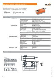
Room Unit<br />
T24-MP<br />
Product overview<br />
The newly developed T24-MP room unit provides the<br />
foundation for modern single room control concepts.<br />
Features<br />
Blue backlight LCD display<br />
Built-in NTC type sensing element<br />
Room/Setpoint temperature display<br />
Minimum setpoint limitation<br />
Diagnostic socket for servicing devices<br />
Working in group with T24-V... Room Control Module<br />
Technical data<br />
Subject to technical change , V6.1 01042010<br />
Nominal voltage<br />
AC 24 V 50/60 Hz<br />
Power supply range<br />
AC 19.2...28.8 V<br />
Wiring terminals Screw terminals, 0.5...1.5 mm 2<br />
Power consumption<br />
1.5VA @ AC 24V, 50/60 Hz<br />
Backlight<br />
Blue backlight (automatically switches on 10s after any key pressed)<br />
Sensing range 5...40 °C, Type NTC, 10kOhm@25 °C<br />
<strong>Operation</strong> mode<br />
Normal / Standby / Economy / Commissioning selection<br />
Display resolution<br />
0.5K (0.1K internal calculation)<br />
Normal setpoint range<br />
10...30 °C, at 0.5K step (Factory setting = 24°C)<br />
Commissioning mode<br />
By press “ ” + “ MODE ” for 5s<br />
Economy setpoint range heating<br />
10...20 °C, at 0.5K step (Factory setting = 18°C)<br />
Economy setpoint range cooling<br />
20...30 °C, at 0.5K step (Factory setting = 28°C)<br />
Cooling or Heating P band<br />
0.5, 1 or 2K<br />
Integral time<br />
60-300s, at 30s step<br />
Application number input By pressing “ ” “ ” buttons<br />
Communication bus<br />
Standard <strong>Belimo</strong> MP connection<br />
Protection class<br />
III Safety extra-low voltage<br />
Degree of protection<br />
IP30<br />
Low-voltage directive<br />
CE according to 2006/95/EC<br />
EMC directive<br />
CE according to 2004/108/EC<br />
Ambient conditions 0...+50 °C<br />
Non-operating temperature -10...+60 °C<br />
Ambient humidity range<br />
5...95% r.h., non-condensing<br />
Weight<br />
108 g<br />
Dimensions (L x W x H)<br />
110 x 84 x 25 mm<br />
Mounting<br />
Surface mounted<br />
<strong>Operation</strong> modes<br />
Short pressing the “ MODE ” key for 2s continuously will allow you to change the operation mode as follows:<br />
Standby Normal Standby mode: All I/O are switched off.<br />
Normal mode: Room unit works according to the setpoint selected by the user.<br />
Override<br />
Override mode: Users can override the Standby mode ordered by BMS, and set 1 ~ 12<br />
hours to extend the operation in Normal mode.<br />
Economy mode: Triggered by digital input and works with economy setpoint.<br />
Long pressing the “ ” + “ MODE ” key for 5s continuously will allow you to enter Commissioning mode for parameter setting.<br />
Blue backlight will always be ON during the Commissioning mode. Moreover, the system will NOT return to Normal mode until<br />
keys are pressed correctly through Standby mode.<br />
To be opened by accredited servicing agents only<br />
Electronic control - Type 2.B action (micro-disconnection operation)<br />
Separate collection for electrical and electronic equipment<br />
15
Room Unit<br />
T24-MP<br />
Wiring diagram<br />
Please note: A standard RJ12 6/4 (1:1)<br />
cable can be plugged onto the RJ12 and<br />
connected to a <strong>Belimo</strong> MP-Bus level<br />
converter (e.g. ZTH-USB-MP) for the<br />
<strong>Belimo</strong> PC-Tool.<br />
Room unit with LCD display and MMI functions<br />
1<br />
1 2 5<br />
2<br />
5<br />
RJ<br />
12<br />
RJ 12<br />
<br />
AC 24V<br />
~<br />
MP<br />
Services tools connection<br />
LCD display<br />
ON<br />
C<br />
Principle of the functional keys<br />
MODE<br />
There are three functional keys on the cover of<br />
T24-MP. The function of the buttons are listed<br />
below.<br />
MODE<br />
Functional keys<br />
Functional Keys<br />
MODE<br />
Function<br />
Normal mode: Increment the temperature setpoint value<br />
Commissioning mode: Adjust options of parameters.<br />
Normal mode: Decrement the temperature setpoint value<br />
Commissioning mode: Adjust options of parameters.<br />
Standby mode or Normal mode selection.<br />
Commissioning mode: Change parameters.<br />
+ MODE Switch from “Normal mode” to “Commissioning mode”<br />
by pressing “ ”+ “ MODE ” for 5 seconds<br />
Dimensions [mm]<br />
84<br />
110<br />
105<br />
60<br />
84<br />
25<br />
16
Room Temperature Sensor<br />
TG-R10000<br />
Product overview<br />
The room temperature sensors are<br />
primarily used to transmit the measured<br />
air temperature on wall.<br />
For surface mounting<br />
Specifications<br />
Model number<br />
TG-R10000<br />
Wiring terminals Screw terminals, 0.5...1.5 mm 2<br />
Sensing element<br />
NTC Thermistor, 10kΩ@25°C, See Table 1 for characteristics<br />
Range<br />
0...40°C<br />
Accuracy<br />
+/- 1K<br />
Degree of protection<br />
IP30<br />
Ambient humidity range<br />
5...95% r.h., non-condensing<br />
Weight<br />
100 g<br />
Dimensions ( L x W x H )<br />
110 x 84 x 25 mm<br />
Resistance versus Temperature<br />
Temperature<br />
°C<br />
Resistance<br />
Ω<br />
Temperature<br />
°C<br />
Resistance<br />
Ω<br />
Temperature<br />
°C<br />
Resistance<br />
Ω<br />
Temperature<br />
°C<br />
Resistance<br />
Ω<br />
0<br />
27780<br />
11<br />
17550<br />
21<br />
11850<br />
31<br />
8160<br />
1<br />
26610<br />
12<br />
16860<br />
22<br />
11400<br />
32<br />
7869<br />
2<br />
25490<br />
13<br />
16190<br />
23<br />
10980<br />
33<br />
7590<br />
3<br />
24430<br />
14<br />
15560<br />
24<br />
10570<br />
34<br />
7323<br />
4<br />
23420<br />
15<br />
14950<br />
25<br />
10180<br />
35<br />
7066<br />
5<br />
22450<br />
16<br />
14370<br />
26<br />
9808<br />
36<br />
6821<br />
6<br />
21540<br />
17<br />
13820<br />
27<br />
9450<br />
37<br />
6585<br />
7<br />
20660<br />
18<br />
13300<br />
28<br />
9107<br />
38<br />
6359<br />
8<br />
19830<br />
19<br />
12790<br />
29<br />
8779<br />
39<br />
5142<br />
9<br />
19040<br />
20<br />
12310<br />
30<br />
8464<br />
40<br />
5933<br />
10<br />
18290<br />
Dimensions [mm]<br />
Subject to technical change V3.1 01042010<br />
84<br />
60<br />
110<br />
84<br />
105<br />
25<br />
Do not open the sensor cover.<br />
No serviceable parts inside.<br />
To be opened by accredited servicing agents only<br />
17
T24-V42(-V02)...+T24-MP<br />
Application Description<br />
Application Description<br />
The following room control applications are pre-stored in the module. Applications number can be selected by Room Unit through<br />
MP-bus commands or BMS through LonWorks or BACnet network.<br />
Appl.<br />
no.<br />
Sequence Description Appl.<br />
Sequence Description<br />
no.<br />
10<br />
Cool only<br />
21<br />
Cool + parallel fan<br />
w/ deadband<br />
20<br />
Heat (or Cool)**<br />
Factory setting = Heat<br />
31<br />
Cool + parallel fan<br />
w/ deadband<br />
Electric reheat 1<br />
1K reheat switching<br />
differential<br />
30<br />
Cool<br />
w/ deadband<br />
Electric reheat 1<br />
1K reheat switching<br />
differential<br />
41<br />
Cool + parallel fan<br />
w/ deadband<br />
Electric reheat 1 & 2<br />
1K reheat switching<br />
differential<br />
40<br />
Cool<br />
w/ deadband<br />
Electric reheat 1 & 2<br />
1K reheat switching<br />
differential<br />
51<br />
Cool + parallel fan<br />
w/ deadband<br />
3-point reheat<br />
1K reheat switching<br />
differential<br />
50<br />
Cool<br />
w/ deadband<br />
3-point reheat<br />
61<br />
Cool + parallel fan<br />
w/ deadband<br />
Modulating reheat<br />
1K reheat switching<br />
differential<br />
60<br />
Cool<br />
w/ deadband<br />
Modulating reheat<br />
19
T24-V42(-V02)...+T24-MP<br />
Application Description<br />
Application Description<br />
The following room control applications are pre-stored in the module. Applications number can be selected by room unit through<br />
MP-bus commands or BMS through LonWorks or BACnet network.<br />
Appl.<br />
no.<br />
Sequence Description Appl.<br />
Sequence Description<br />
no.<br />
12<br />
Cool only + series fan*<br />
42<br />
Cool + series fan*<br />
w/ deadband<br />
Electric reheat 1 & 2<br />
1K reheat switching<br />
differential<br />
22<br />
Heat (or Cool)** +<br />
series fan*<br />
Factory setting = Heat<br />
52<br />
Cool + series fan*<br />
w/ deadband<br />
3-point reheat<br />
32<br />
Cool + series fan*<br />
w/ deadband<br />
Electric reheat 1<br />
1K reheat switching<br />
differential<br />
62<br />
Cool + series fan*<br />
w/ deadband<br />
Modulating reheat<br />
* Series fan (DO3) will always be ON in Normal / Economy / Override modes. It will automatically switch OFF in Standby mode.<br />
** Heat / Cool changeover function in Application 20 & 22 shall manually be selected by BMS via LonWorks or BACnet network.<br />
*** T24-V02LON and T24-V02BAC functions under in Application 10 & 20.<br />
20
T24-V42(-V02)...+T24-MP<br />
Application Description<br />
Application No. 10 - Cool only<br />
- VAV single duct application<br />
The room temperature aims as the demand related<br />
control value of the connected VAV units. The variable<br />
volumetric air flow range V’min...V’max:<br />
T24-MP<br />
-V’min - to the hygienic change or minimum fresh air<br />
-V’max - to the maximum cooling demand<br />
VAV Compact<br />
Control Module<br />
*Max for 2 VAV box<br />
connected together<br />
BACnet / LonWorks<br />
Functional diagram<br />
%<br />
Options<br />
100<br />
Cooling<br />
Vmax<br />
- AI External temp. sensor, NTC 10k@25°C sensor<br />
- DI Remote setpoint shift, e.g. Occupancy sensor (NO)<br />
Open - Normal mode, Close - Economy mode<br />
W<br />
Vmin<br />
T [ 0 C]<br />
<strong>Operation</strong>s - MMI<br />
- T24-MP with user interface, LCD display<br />
#10: Cool only Econ mode<br />
- TG-R10000 without user interface, No display<br />
Application No. 20 - Heat (or Cool) *<br />
- VAV single duct application<br />
The room temperature aims as the demand related<br />
control value of the connected VAV units. The variable<br />
volumetric air flow range V’min...V’max:<br />
T24-MP<br />
-V’min - to the hygienic change or minimum fresh air<br />
-V’max - to the maximum cooling / heating demand<br />
VAV Compact Control Module<br />
*Max for 2 VAV box<br />
connected together<br />
BACnet / LonWorks<br />
* Factory setting = Heat<br />
Heat or cool changeover shall manually be selected<br />
by BMS via BACnet / LonWorks<br />
Functional diagram<br />
%<br />
Options<br />
100<br />
Heating<br />
Cooling<br />
Vmax<br />
- AI External temp. sensor, NTC 10k@25°C sensor<br />
- DI Remote setpoint shift, e.g. Occupancy sensor (NO)<br />
Open - Normal mode, Close - Economy mode<br />
W<br />
Vmin<br />
T [ 0 C]<br />
Heat mode<br />
#20: Heat or Cool Econ mode<br />
<strong>Operation</strong>s - MMI<br />
- T24-MP with user interface, LCD display<br />
- TG-R10000 without user interface, No display<br />
21
T24-V42(-V02)...+T24-MP<br />
Application Description<br />
Application No. 30 - Cool with 1-stage electric reheat<br />
- VAV single duct application<br />
I<br />
The room temperature aims as the demand related<br />
control value of the connected VAV units. The variable<br />
volumetric air flow range V’min...V’max:<br />
T24-MP<br />
-V’min - to the hygienic change or minimum fresh air<br />
-V’max - to the maximum cooling demand<br />
VAV Compact Control Module<br />
*Max for 2 VAV box<br />
connected together<br />
Functional diagram<br />
%<br />
BACnet / LonWorks<br />
Options<br />
At heating conditions the electric reheat gets<br />
controlled via the digital output - DO1<br />
100<br />
El. 1<br />
Cooling<br />
Vmax<br />
- AI External temp. sensor, NTC 10k@25°C sensor<br />
- DI Remote setpoint shift, e.g. Occupancy sensor (NO)<br />
Open - Normal mode, Close - Economy mode<br />
1K<br />
#30:<br />
Cool + 1-stage El. reheat<br />
DB<br />
W<br />
Vmin<br />
T [ 0 C]<br />
Heating mode<br />
reheat<br />
Econ mode<br />
<strong>Operation</strong>s - MMI<br />
- T24-MP with user interface, LCD display<br />
- TG-R10000 without user interface, No display<br />
Application No. 40 - Cool with 2-stages electric reheat<br />
- VAV single duct application<br />
I, II<br />
The room temperature aims as the demand related<br />
control value of the connected VAV units. The variable<br />
volumetric air flow range V’min...V’max:<br />
T24-MP<br />
-V’min - to the hygienic change or minimum fresh air<br />
-V’max - to the maximum cooling demand<br />
VAV Compact Control Module<br />
*Max for 2 VAV box<br />
connected together<br />
BACnet / LonWorks<br />
At heating conditions the 2-steps electric reheat<br />
gets controlled via two digital outputs - DO1 & DO2<br />
Functional diagram<br />
%<br />
Options<br />
100<br />
El. 2<br />
Cooling<br />
Vmax<br />
- AI External temp. sensor, NTC 10k@25°C sensor<br />
El. 1<br />
- DI Remote setpoint shift, e.g. Occupancy sensor (NO)<br />
Open - Normal mode, Close - Economy mode<br />
1K 1K<br />
#40:<br />
Cool + 2-stages El. reheat<br />
DB<br />
W<br />
Vmin<br />
T [ 0 C]<br />
Heating mode<br />
reheat<br />
Econ mode<br />
<strong>Operation</strong>s - MMI<br />
- T24-MP with user interface, LCD display<br />
- TG-R10000 without user interface, No display<br />
22
T24-V42(-V02)...+T24-MP<br />
Application Description<br />
Application No. 50 - Cool with 3-point reheat<br />
- VAV single duct application<br />
The room temperature aims as the demand related<br />
control value of the connected VAV units. The variable<br />
volumetric air flow range V’min...V’max:<br />
T24-MP<br />
-V’min - to the hygienic change or minimum fresh air<br />
-V’max - to the maximum cooling demand<br />
VAV Compact Control Module<br />
*Max for 2 VAV box<br />
connected together<br />
Functional diagram<br />
BACnet / LonWorks<br />
At heating conditions the 3 point reheat valve gets<br />
controlled via two digital outputs - DO1 & DO2<br />
%<br />
Options<br />
100<br />
Heating<br />
Cooling<br />
Vmax<br />
- AI External temp. sensor, NTC 10k@25°C sensor<br />
- DI Remote setpoint shift, e.g. Occupancy sensor (NO)<br />
Open - Normal mode, Close - Economy mode<br />
Vmin<br />
T [ 0 C]<br />
<strong>Operation</strong>s - MMI<br />
#50:<br />
Cool + 3-point reheat<br />
DB<br />
W<br />
3-point reheat<br />
Econ mode<br />
- T24-MP with user interface, LCD display<br />
- TG-R10000 without user interface, No display<br />
Application No. 60 - Cool with modulating reheat<br />
- VAV single duct application<br />
The room temperature aims as the demand related<br />
control value of the connected VAV units. The variable<br />
volumetric air flow range V’min...V’max:<br />
T24-MP<br />
-V’min - to the hygienic change or minimum fresh air<br />
-V’max - to the maximum cooling demand<br />
VAV Compact Control Module<br />
*Max for 2 VAV box<br />
connected together<br />
BACnet / LonWorks<br />
At heating conditions the modulating reheat valve gets<br />
controlled via the analogue output - AO<br />
Functional diagram<br />
%<br />
Options<br />
100<br />
Heating<br />
Cooling<br />
Vmax<br />
- AI External temp. sensor, NTC 10k@25°C sensor<br />
- DI Remote setpoint shift, e.g. Occupancy sensor (NO)<br />
Open - Normal mode, Close - Economy mode<br />
#60:<br />
Cool + Mod. reheat<br />
DB<br />
W<br />
Vmin<br />
T [ 0 C]<br />
Mod reheat<br />
Econ mode<br />
<strong>Operation</strong>s - MMI<br />
- T24-MP with user interface, LCD display<br />
- TG-R10000 without user interface, No display<br />
23
T24-V42(-V02)...+T24-MP<br />
Application Description<br />
Application No. 21 - Cool with parallel fan<br />
- VAV single duct application<br />
The room temperature aims as the demand related<br />
control value of the connected VAV units. The variable<br />
volumetric air flow range V’min...V’max:<br />
T24-MP<br />
-V’min - to the hygienic change or minimum fresh air<br />
-V’max - to the maximum cooling demand<br />
VAV Compact Control Module<br />
*Max for 2 VAV box<br />
connected together<br />
Functional diagram<br />
%<br />
BACnet / LonWorks<br />
Options<br />
At heating conditions the parallel fan gets controlled<br />
via the digital output - DO3<br />
100<br />
Fan<br />
Cooling<br />
Vmax<br />
- AI External temp. sensor, NTC 10k@25°C sensor<br />
- DI Remote setpoint shift, e.g. Occupancy sensor (NO)<br />
Open - Normal mode, Close - Economy mode<br />
DB<br />
W<br />
Vmin<br />
T [ 0 C]<br />
#21: Cool + Parallel Fan Econ mode<br />
<strong>Operation</strong>s - MMI<br />
- T24-MP with user interface, LCD display<br />
- TG-R10000 without user interface, No display<br />
Application No. 31 - Cool with 1-stage electric reheat & parallel fan<br />
- VAV single duct application<br />
I<br />
The room temperature aims as the demand related<br />
control value of the connected VAV units. The variable<br />
volumetric air flow range V’min...V’max:<br />
-V’min - to the hygienic change or minimum fresh air<br />
T24-MP<br />
-V’max - to the maximum cooling demand<br />
VAV Compact Control Module<br />
*Max for 2 VAV box<br />
connected together<br />
Functional diagram<br />
BACnet / LonWorks<br />
At heating conditions the electric reheat & parallel<br />
fan gets controlled via two digital outputs - DO1 & DO3<br />
If the room setpoint suddenly increases, the electric reheat<br />
function will automatically switch off. The control<br />
module will delay 1 mins to switch off parallel fan as<br />
precaution in case of high temp. inside the air duct.<br />
100<br />
%<br />
El. 1<br />
Cooling<br />
Vmax<br />
Options<br />
- AI External temp. sensor, NTC 10k@25°C sensor<br />
Fan<br />
1K DB<br />
W<br />
#31:<br />
Cool + Parallel fan + 1-stage El. reheat<br />
Vmin<br />
T [ 0 C]<br />
reheat and<br />
Fan<br />
Econ mode<br />
- DI Remote setpoint shift, e.g. Occupancy sensor (NO)<br />
Open - Normal mode, Close - Economy mode<br />
<strong>Operation</strong>s - MMI<br />
- T24-MP with user interface, LCD display<br />
- TG-R10000 without user interface, No display<br />
24
T24-V42(-V02)...+T24-MP<br />
Application Description<br />
Application No. 41 - Cool with 2-stages electric reheat & parallel fan<br />
- VAV single duct application<br />
I, II<br />
The room temperature aims as the demand related<br />
control value of the connected VAV units. The variable<br />
volumetric air flow range V’min...V’max:<br />
-V’min - to the hygienic change or minimum fresh air<br />
VAV Compact Control Module<br />
*Max for 2 VAV box<br />
connected together<br />
Functional diagram<br />
T24-MP<br />
BACnet / Lonworks<br />
-V’max - to the maximum cooling demand<br />
At heating conditions the 2-steps electric reheat<br />
& parallel fan gets controlled via three digital outputs<br />
- DO1, DO2 & DO3<br />
If the room setpoint suddenly increases, the electric reheat<br />
function will automatically switch off. The control<br />
module will delay 1 mins to switch off parallel fan as<br />
precaution in case of high temp. inside the air duct.<br />
100<br />
%<br />
El. 2<br />
El. 1<br />
Fan<br />
Cooling<br />
Vmax<br />
Options<br />
- AI External temp. sensor, NTC 10k@25°C sensor<br />
- DI Remote setpoint shift, e.g. Occupancy sensor (NO)<br />
Open - Normal mode, Close - Economy mode<br />
1K 1K 1K DB<br />
W<br />
#41:<br />
Cool + Parallel Fan + 2-stages El. reheat<br />
Vmin<br />
T [ 0 C]<br />
reheat and<br />
Fan<br />
Econ mode<br />
<strong>Operation</strong>s - MMI<br />
- T24-MP with user interface, LCD display<br />
- TG-R10000 without user interface, No display<br />
Application No. 51 - Cool with 3-point reheat & parallel fan<br />
- VAV single duct application<br />
The room temperature aims as the demand related<br />
control value of the connected VAV units. The variable<br />
volumetric air flow range V’min...V’max:<br />
T24-MP<br />
-V’min - to the hygienic change or minimum fresh air<br />
-V’max - to the maximum cooling demand<br />
VAV Compact Control Module<br />
*Max for 2 VAV box<br />
connected together<br />
BACnet / LonWorks<br />
Under heating conditions the 3-point reheat valve &<br />
parallel fan gets controlled via three digital outputs<br />
- DO1, DO2 & DO3<br />
Functional diagram<br />
%<br />
Options<br />
100<br />
Heating<br />
Cooling<br />
Vmax<br />
- AI External temp. sensor, NTC 10k@25°C sensor<br />
Fan<br />
1K DB<br />
W<br />
#51:<br />
Cool + Parallel Fan + 3-point reheat<br />
Vmin<br />
T [ 0 C]<br />
3-point reheat<br />
and Fan<br />
Econ mode<br />
- DI Remote setpoint shift, e.g. Occupancy sensor (NO)<br />
Open - Normal mode, Close - Economy mode<br />
<strong>Operation</strong>s - MMI<br />
- T24-MP with user interface, LCD display<br />
- TG-R10000 without user interface, No display<br />
25
T24-V42(-V02)...+T24-MP<br />
Application Description<br />
Application No. 61 - Cool with modulating reheat & parallel fan<br />
- VAV single duct application<br />
The room temperature aims as the demand related<br />
control value of the connected VAV units. The variable<br />
volumetric air flow range V’min...V’max:<br />
T24-MP<br />
-V’min - to the hygienic change or minimum fresh air<br />
-V’max - to the maximum cooling demand<br />
VAV Compact Control Module<br />
*Max for 2 VAV box<br />
connected together<br />
Functional diagram<br />
BACnet / LonWorks<br />
Under heating conditions the modulating reheat valve<br />
& parallel fan gets controlled via analogue and digital<br />
output - AO & DO3<br />
%<br />
Options<br />
100<br />
Heating<br />
Cooling<br />
Vmax<br />
- AI External temp. sensor, NTC 10k@25°C sensor<br />
Fan<br />
1K DB<br />
W<br />
#61:<br />
Cool + Parallel Fan + Modulating reheat<br />
Vmin<br />
T [ 0 C]<br />
Mod. reheat<br />
and Fan<br />
Econ mode<br />
- DI Remote setpoint shift, e.g. Occupancy sensor (NO)<br />
Open - Normal mode, Close - Economy mode<br />
<strong>Operation</strong>s - MMI<br />
- T24-MP with user interface, LCD display<br />
- TG-R10000 without user interface, No display<br />
Application No. 12 - Cool with series fan<br />
- VAV single duct application<br />
The room temperature aims as the demand related<br />
control value of the connected VAV units. The variable<br />
volumetric air flow range V’min...V’max:<br />
T24-MP<br />
-V’min - to the hygienic change or minimum fresh air<br />
-V’max - to the maximum cooling demand<br />
Under normal conditions the series fan gets controlled<br />
via digital output - DO3<br />
VAV Compact Control Module<br />
*Max for 2 VAV box<br />
connected together<br />
BACnet / LonWorks<br />
* During the normal operation, the series fan will<br />
always on.<br />
Functional diagram<br />
%<br />
Options<br />
100<br />
Cooling<br />
Vmax<br />
- AI External temp. sensor, NTC 10k@25°C sensor<br />
- DI Remote setpoint shift, e.g. Occupancy sensor (NO)<br />
Open - Normal mode, Close - Economy mode<br />
W<br />
Vmin<br />
T [ 0 C]<br />
#12: Cool only Econ mode<br />
<strong>Operation</strong>s - MMI<br />
- T24-MP with user interface, LCD display<br />
- TG-R10000 without user interface, No display<br />
26
T24-V42(-V02)...+T24-MP<br />
Application Description<br />
Application No. 22 - Heat (or Cool) with series fan *<br />
- VAV single duct application<br />
The room temperature aims as the demand related<br />
control value of the connected VAV units. The variable<br />
volumetric air flow range V’min...V’max:<br />
-V’min - to the hygienic change or minimum fresh air<br />
T24-MP<br />
-V’max - to the maximum cooling / heating demand<br />
Under normal conditions the series fan gets controlled<br />
via the digital output - DO3<br />
VAV Compact Control Module<br />
*Max for 2 VAV box<br />
connected together<br />
Functional diagram<br />
BACnet / LonWorks<br />
* During the normal operation, the series fan will<br />
always on.<br />
* Factory setting = Heat<br />
Heat or cool changeover shall manually be selected<br />
by BMS via BACnet / LonWorks<br />
%<br />
Options<br />
100<br />
Heating<br />
Cooling<br />
Vmax<br />
- AI External temp. sensor, NTC 10k@25°C sensor<br />
- DI Remote setpoint shift, e.g. Occupancy sensor (NO)<br />
Open - Normal mode, Close - Economy mode<br />
W<br />
Vmin<br />
T [ 0 C]<br />
Heat mode<br />
#22: Heat or Cool Econ mode<br />
<strong>Operation</strong>s - MMI<br />
- T24-MP with user interface, LCD display<br />
- TG-R10000 without user interface, No display<br />
Application No. 32 - Cool with 1-stage electric reheat & series fan<br />
- VAV single duct application<br />
I<br />
The room temperature aims as the demand related<br />
control value of the connected VAV units. The variable<br />
volumetric air flow range V’min...V’max:<br />
-V’min - to the hygienic change or minimum fresh air<br />
T24-MP<br />
-V’max - to the maximum cooling demand<br />
VAV Compact Control Module<br />
*Max for 2 VAV box<br />
connected together<br />
Functional diagram<br />
BACnet / LonWorks<br />
Under heating conditions the electric reheat &<br />
series fan gets controlled via two digital outputs -<br />
DO1 & DO3<br />
* During the normal operation, the series fan will<br />
always on.<br />
%<br />
Options<br />
100<br />
El. 1<br />
Cooling<br />
Vmax<br />
- AI External temp. sensor, NTC 10k@25°C sensor<br />
- DI Remote setpoint shift, e.g. Occupancy sensor (NO)<br />
Open - Normal mode, Close - Economy mode<br />
1K<br />
#32:<br />
Cool + 1-stage El. reheat<br />
DB<br />
W<br />
Vmin<br />
T [ 0 C]<br />
Heating mode<br />
reheat<br />
Econ mode<br />
<strong>Operation</strong>s - MMI<br />
- T24-MP with user interface, LCD display<br />
- TG-R10000 without user interface, No display<br />
27
T24-V42(-V02)...+T24-MP<br />
Application Description<br />
Application No. 42 - Cool with 2-stages electric reheat & series fan<br />
- VAV single duct application<br />
I, II<br />
The room temperature aims as the demand related<br />
control value of the connected VAV units. The variable<br />
volumetric air flow range V’min...V’max:<br />
-V’min - to the hygienic change or minimum fresh air<br />
T24-MP<br />
-V’max - to the maximum cooling demand<br />
VAV Compact Control Module<br />
*Max for 2 VAV box<br />
connected together<br />
Functional diagram<br />
BACnet / LonWorks<br />
Under heating conditions the 2-steps electric reheat<br />
& series fan gets controlled via three digital outputs -<br />
DO1, DO2 & DO3<br />
* During the normal operation, the series fan will<br />
always on.<br />
%<br />
Options<br />
100<br />
El. 2<br />
Cooling<br />
Vmax<br />
- AI External temp. sensor, NTC 10k@25°C sensor<br />
El. 1<br />
- DI Remote setpoint shift, e.g. Occupancy sensor (NO)<br />
Open - Normal mode, Close - Economy mode<br />
1K 1K<br />
#42:<br />
Cool + 2-stages El. reheat<br />
DB<br />
W<br />
Vmin<br />
T [ 0 C]<br />
Heating mode<br />
reheat<br />
Econ mode<br />
<strong>Operation</strong>s - MMI<br />
- T24-MP with user interface, LCD display<br />
- TG-R10000 without user interface, No display<br />
Application No. 52 - Cool with 3-point reheat & series fan<br />
- VAV single duct application<br />
The room temperature aims as the demand related<br />
control value of the connected VAV units. The variable<br />
volumetric air flow range V’min...V’max:<br />
-V’min - to the hygienic change or minimum fresh air<br />
T24-MP<br />
-V’max - to the maximum cooling demand<br />
VAV Compact Control Module<br />
*Max for 2 VAV box<br />
connected together<br />
Functional diagram<br />
BACnet / LonWorks<br />
Under heating conditions the 3 point reheat valve &<br />
series fan gets controlled via three digital outputs -<br />
DO1, DO2 & DO3<br />
* During the normal operation, the series fan will<br />
always on.<br />
%<br />
Options<br />
100<br />
Heating<br />
Cooling<br />
Vmax<br />
- AI External temp. sensor, NTC 10k@25°C sensor<br />
- DI Remote setpoint shift, e.g. Occupancy sensor (NO)<br />
Open - Normal mode, Close - Economy mode<br />
Vmin<br />
T [ 0 C]<br />
<strong>Operation</strong>s - MMI<br />
#52:<br />
Cool + 3-point reheat<br />
DB<br />
W<br />
3-point reheat<br />
Econ mode<br />
- T24-MP with user interface, LCD display<br />
- TG-R10000 without user interface, No display<br />
28
T24-V42(-V02)...+T24-MP<br />
Application Description<br />
Application No. 62 - Cool with modulating reheat & series fan<br />
- VAV single duct application<br />
The room temperature aims as the demand related<br />
control value of the connected VAV units. The variable<br />
volumetric air flow range V’min...V’max:<br />
-V’min - to the hygienic change or minimum fresh air<br />
T24-MP<br />
-V’max - to the maximum cooling demand<br />
VAV Compact Control Module<br />
*Max for 2 VAV box<br />
connected together<br />
Functional diagram<br />
%<br />
BACnet / LonWorks<br />
Options<br />
Under heating conditions the modulating reheat valve<br />
& series fan gets controlled via analogue and digital<br />
output - AO & DO3<br />
* During the normal operation, the series fan will<br />
always on.<br />
100<br />
Heating<br />
Cooling<br />
Vmax<br />
- AI External temp. sensor, NTC 10k@25°C sensor<br />
- DI Remote setpoint shift, e.g. Occupancy sensor (NO)<br />
Open - Normal mode, Close - Economy mode<br />
#62:<br />
Cool + Mod. reheat<br />
DB<br />
W<br />
Vmin<br />
T [ 0 C]<br />
Mod reheat<br />
Econ mode<br />
<strong>Operation</strong>s - MMI<br />
- T24-MP with user interface, LCD display<br />
- TG-R10000 without user interface, No display<br />
29
T24-V42(-V02)...+T24-MP<br />
<strong>Operation</strong> and setting<br />
Controller operation<br />
The T24-V42(-V02)... room control module offers the advantages of network control via the high performance network protocol.<br />
This controller features clear LED’s indication, analogue input, digital input, analogue output, 3 x AC 24V digital outputs. MP-Bus<br />
interface for connection to the <strong>Belimo</strong> VAV Compact and optional T24-MP room unit or TG-R10000 room sensor. Suitable for new<br />
or existing VAV system installations.<br />
Functions of T24-V42(-V02)LON and wiring diagram<br />
External<br />
sensor (AI)<br />
NTC 10k<br />
Analogue<br />
output (AO)<br />
2-10Vdc<br />
AC 24V<br />
Power<br />
supply<br />
MP-Bus (MP1~3)<br />
LonWorks<br />
(TG-R10000)<br />
External<br />
sensor<br />
NTC 10k<br />
*Power<br />
supply<br />
M<br />
Modulating<br />
reheat valve<br />
T24-MP<br />
1 2 5<br />
1A fuse<br />
AC 24V<br />
~ <br />
1 A<br />
1 2 3 5<br />
1 2 3 5<br />
VAV Compact<br />
VAV Compact<br />
LonWorks®<br />
AI<br />
Com<br />
AO<br />
Com<br />
24V<br />
Com MP1 MP2 MP3<br />
ac<br />
LON LON<br />
A B<br />
DI<br />
Com<br />
DO1 Com DO2 Com DO3 Com<br />
1 2 3<br />
AC 24V<br />
Power DO1 DO2 DO3 Signal<br />
MP<br />
BUS <br />
Occupancy<br />
sensor<br />
M<br />
*Relay supplied<br />
by others<br />
3-point<br />
reheat<br />
valve<br />
Caution: live voltage<br />
Digital input<br />
(DI)<br />
Electrical heaters,<br />
parallel/series fan<br />
(3 x DO)<br />
System<br />
reset<br />
LonWorks<br />
service pin<br />
xxx<br />
Heater<br />
1<br />
Only available for T24-V42LON<br />
Heater<br />
2<br />
Fan<br />
System<br />
reset<br />
LonWorks<br />
service pin<br />
Functions of T24-V42(-V02)BAC and wiring diagram<br />
Electrical heaters,<br />
parallel/series fan<br />
(3 x DO)<br />
AC 24V<br />
Power<br />
supply<br />
MP-Bus (MP1~3)<br />
M<br />
Heater<br />
1<br />
Heater<br />
2<br />
Fan<br />
1A fuse<br />
AC 24V<br />
~ <br />
1 A<br />
1 2 3 5<br />
3-point<br />
reheat<br />
valve<br />
Com DO1 Com DO2 Com<br />
DO3<br />
*Relay<br />
supplied<br />
by others<br />
AC 24V<br />
Caution: live voltage<br />
1 2 5<br />
1 2 3 5<br />
VAV Compact<br />
24V<br />
Com MP1 MP2 MP3<br />
ac<br />
VAV Compact<br />
1 2 3<br />
AO Com AI<br />
Com DI Com<br />
D+<br />
D-<br />
Com SHLD<br />
Subject to technical change V2.0 01042010<br />
Software<br />
reflash<br />
System<br />
reset<br />
Power DO1 DO2 DO3 Signal<br />
Analogue<br />
output (AO)<br />
2-10Vdc<br />
External<br />
sensor (AI)<br />
NTC 10k<br />
Input & output assignment<br />
Inputs<br />
- AI External temp. sensor TG-R10000 *<br />
- DI Remote setpoint shift, e.g. Occupancy sensor *<br />
Open - Normal mode, Close - Economy mode<br />
MP<br />
Digital input<br />
(DI)<br />
BUS <br />
BACnet<br />
xxx<br />
M<br />
*Power<br />
supply<br />
* Optional Outputs<br />
External<br />
sensor<br />
NTC 10k<br />
(TG-R10000)<br />
Only available for T24-V42BAC<br />
Occupancy<br />
sensor<br />
To<br />
From<br />
MS/TP<br />
Next Device Last Device<br />
BACnet®<br />
System<br />
reset<br />
- AO Modulating reheat control DC 2...10V<br />
- DO1 Heating output I AC 24V ON/OFF<br />
- DO2 Heating output II AC 24V ON/OFF<br />
- DO3 Parallel or series fan output AC 24V ON/OFF<br />
31
T24-V42(-V02)...+T24-MP<br />
<strong>Operation</strong> and setting<br />
Functions of T24-MP and wiring diagram<br />
LCD display<br />
Room unit with LCD display and MMI functions<br />
C<br />
ON<br />
1<br />
1 2 5<br />
2<br />
5<br />
RJ<br />
12<br />
RJ 12<br />
<br />
AC 24V<br />
~<br />
MP<br />
Services tools connection<br />
MODE<br />
Functional keys<br />
Please note: A standard RJ12 6/4 (1:1)<br />
cable can be plugged onto the RJ12 and<br />
connected to a <strong>Belimo</strong> MP-Bus level<br />
converter (e.g. ZTH-USB-MP) for the<br />
<strong>Belimo</strong> PC-Tool.<br />
Functions of TG-R10000 and wiring diagram<br />
Room sensor without MMI function<br />
1<br />
1<br />
2<br />
2<br />
External sensor NTC 10k<br />
Mounting notes<br />
The T24-V42(-V02)... control module can be mounted as follows:<br />
Observe all local installation and mounting regulations.<br />
DIN rail (EN 50 022-35 x 7.5) at least 120 mm long<br />
Wall mounted with 2 screws<br />
The T24-MP or TG-R10000 room unit can be mounted as follows:<br />
Wall mounted. Not in niches or bookshelves, not behind curtains, above or near heat sources and exposed to direct solar<br />
radiation. Mounting height is about 1.5 m above the floor. The connecting wires can be run to the controller from a recessed<br />
conduit box.<br />
32
T24-V42(-V02)...+T24-MP<br />
<strong>Operation</strong> and setting<br />
Electrical requirement<br />
The room control module is designed for AC 24 V operating voltage. Standard cables can be used for the devices. However, when<br />
mounting in an environment greatly exposed to EMI, use only shielded cables.<br />
- The low voltage must comply with the requirements for safety extra-low voltage (SELV) as per EN 60730.<br />
- Use safety insulating transformers with double insulation as per EN 60742; they must be designed for 100 % on-time.<br />
- Supplying voltages above AC 24 V to low voltage connections may damage or destroy the control module or any other connected<br />
devices. Additionally, connections to voltages exceeding AC 42 V endanger personal safety.<br />
2<br />
- Wiring terminal: Fixed screw terminals, 0.5...1.5 mm .<br />
Principle operation of TG-R10000<br />
Surface mounting TG-R10000 room sensor directly connected to T24-V42<br />
(-V02)... room module of analoge input (AI) point. This device is without<br />
MMI and LCD display. The room temperature can be read though Building<br />
Management System (BMS) by LonWork / BACnet.<br />
The device would not function if T24-MP is connected together.<br />
Principle functional keys of T24-MP<br />
LCD display<br />
ON<br />
C<br />
MODE<br />
Functional keys<br />
MODE<br />
Functional Keys<br />
Function<br />
There are three functional keys on the cover of T24-MP<br />
The function of the buttons are listed below.<br />
Normal mode: Increment the temperature setpoint value<br />
Commissioning mode: Adjust options of parameters<br />
Normal mode: Decrement the temperature setpoint value<br />
Commissioning mode: Adjust options of parameters<br />
MODE Standby mode or Normal mode selection<br />
Commissioning mode: Change parameters<br />
+ MODE Switch from “Normal mode” to “Commissioning mode”<br />
by pressing “ ”+ “ MODE ” for 5 seconds<br />
<strong>Operation</strong> menu of T24-MP<br />
Menu structure<br />
Standby<br />
mode<br />
Press “ MODE ”<br />
2 sec<br />
Normal<br />
mode<br />
Temperature display<br />
Temperature setpoint<br />
Press<br />
“ MODE ”<br />
Time<br />
out<br />
Press<br />
“ MODE ”<br />
Press<br />
“ ” & “ MODE ” 5 sec<br />
Override<br />
mode<br />
Commissioning<br />
mode<br />
Sub-menu<br />
......<br />
Parameter setpoint<br />
......<br />
Start-up<br />
Device start after power ON<br />
Normal mode<br />
Actual room temperature display<br />
Factory setting of setpoint is 24ºC<br />
33
T24-V42(-V02)...+T24-MP<br />
<strong>Operation</strong> and setting<br />
Parameter setting of T24-MP<br />
It is possible to set different parameter values in Commissioning mode by pressing “ ” and “ MODE ” for 5s continuously.<br />
Parameter values can be changed with the “ ” or “ ” buttons and changes can be confirmed with the “ MODE ” button. After<br />
completing the parameter setup, the system will return to Standby mode and keep storage in memory.<br />
Parameters display<br />
Selectable by “MODE”<br />
Setting range / options<br />
Selectable by and<br />
Description<br />
Factory setting<br />
1<br />
Start to Commissioning mode<br />
(All input/output signals will switch off)<br />
2<br />
Eco<br />
C<br />
10.0...30.0 (ºC), step 0.5<br />
Minimum setpoint limitation in<br />
Normal mode<br />
3<br />
1...3 (K), step 1<br />
P-band in heating mode<br />
4<br />
1...3 (K), step 1<br />
P-band in cooling mode<br />
5<br />
0.5, 1.0, 2.0 (K)<br />
Deadband range<br />
6<br />
Eco<br />
C<br />
10.0...20.0 (ºC), step 0.5<br />
Setpoint of heating in Economy mode<br />
7<br />
Eco<br />
C<br />
20.0...30.0 (ºC), step 0.5<br />
Setpoint of cooling in Economy mode<br />
8<br />
Appl.<br />
10, 20, 30, 40, 50, 60, 21, 31,<br />
41, 61, 12, 22, 32, 42, 52, 62.<br />
Application number selection<br />
9<br />
Int T<br />
ON<br />
60...300 (sec), step 30<br />
Integral action time<br />
10<br />
60...150 (sec), step 10<br />
3 point floating control for reheat valve<br />
11<br />
or<br />
Enable / disable the room unit to override<br />
the Standby mode ordered by BMS<br />
12<br />
or<br />
LCD display: “Setpoint only” or “Room temp.<br />
with setpoint”<br />
13<br />
or<br />
Parameter or flow rates re-set from room<br />
unit - RJ12 plug<br />
#<br />
14<br />
0x00n~0x7Fn<br />
Network address in hex format<br />
(BACnet version only) *<br />
15<br />
0x00n~0x3Fn<br />
Device address 1 in hex format<br />
(BACnet version only) *<br />
16<br />
ON<br />
0x00n~0xFFn<br />
Device address 2 in hex format<br />
(BACnet version only) *<br />
17<br />
ON Eco<br />
0x00n~0xFFn<br />
Device address 3 in hex format<br />
(BACnet version only) *<br />
# The network and device address only to display for connection with BACnet version control module together<br />
* Max. network address for BACnet control module is 0x7F, and the default network address is 0x7F<br />
Max. device address for BACnet control module is 0x3F FF FF, and the default device address is 0x00 00 00<br />
34
T24-V42(-V02)...+T24-MP<br />
<strong>Operation</strong> and setting<br />
MP-Bus - VAV Compact addresses<br />
T24-V42(-V02)..., MP-Bus requirement<br />
The MP-Bus is the <strong>Belimo</strong> master/salve bus. Up to 8 salves can be connected<br />
to a MP-master devices. Each MP salve must be assigned a unique<br />
MP address between MP1 to MP8 before it can be operated on the<br />
MP-Bus. <strong>Belimo</strong> VAV Compacts are set to PP (point-to-point) addressing<br />
on delivery. PP is the required conventional control setting for CAV/VAV<br />
functions with 0...10 / 2...10 V signals.<br />
For T24-V42(-V02)... control module, it can manage up to 3 MP devices<br />
(MP1 to MP3). MP1 is for T24-MP, MP2 and 3 are for VAV-Compacts<br />
connection. MP4 to 8 are not used in this situation.<br />
Pre-addressing with <strong>Belimo</strong> PC-Tool V3.x<br />
VAV Compacts can be pre-addressed with the PC-Tool (address / deaddress<br />
device). Pre-addressed VAV Compacts are automatically detected<br />
and read as soon as they are connected to the T24-V42(-V02)....<br />
Address setting<br />
Room Unit - T24-MP;<br />
It is defaulted as MP1, no need to address with PC-Tool<br />
When 1 VAV Compact is connected with T24-V42(-V02)...;<br />
Pre-address it to MP2 or MP3 with <strong>Belimo</strong> PC-Tool<br />
When 2 VAV Compacts are connected with T24-V42(-V02)...;<br />
Pre-address the first actuator to MP2 and the second actuator to MP3 with<br />
<strong>Belimo</strong> PC-tool<br />
PC-Tool connection<br />
a) On the Room Unit - T24-MP<br />
After the room unit is enable from to in commissioning mode,<br />
the LCD will display "PS" and allow the user to start to operate PC-Tool<br />
by connecting with external hardware device (e.g. ZIP-USB-MP).<br />
The room unit will resume to normal operation if the control module has<br />
not received any commands from PC-Tool after 5 mins. Both MP2 and<br />
MP3 can be read in this situation.<br />
Please note: Bus jam will occur if two or more devices respond to the<br />
same address. Or room unit (T24-MP) and external hardware device<br />
(ZIP-USB-MP) connected toegther in normal operation.<br />
b) On the VAV-Compact<br />
If the PC-Tool is connected locally to the service socket of the<br />
VAV-Compact, it is free to set all the parameters in this MP device. No<br />
other MP devices can be accessed.<br />
The product would not perform normally under mains power fluctuations, or under strong electric fast transient/burst environment<br />
Not to be exposed to dripping or splashing. The unit much be mounted on clean, dry indoor places<br />
To be opened by accredited servicing agents only<br />
Electronic control - Type 2.B action (micro-disconnection operation)<br />
Separate collection for electrical and electronic equipment<br />
35
Innovation, Quality and Consultancy:<br />
A partnership for motorising HVAC actuators<br />
<strong>Belimo</strong> regional offices
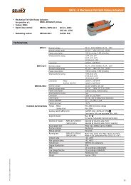
![SV24A-SZ-TPC_datasheet_en[2013.03.26].pdf - Belimo Actuators ...](https://img.yumpu.com/49758098/1/184x260/sv24a-sz-tpc-datasheet-en20130326pdf-belimo-actuators-.jpg?quality=85)

![CCV_V7[2013.07.16].pdf - Belimo Actuators (Shanghai)](https://img.yumpu.com/46161653/1/184x260/ccv-v720130716pdf-belimo-actuators-shanghai.jpg?quality=85)