TTSIM-1 - TraceTek
TTSIM-1 - TraceTek
TTSIM-1 - TraceTek

You also want an ePaper? Increase the reach of your titles
YUMPU automatically turns print PDFs into web optimized ePapers that Google loves.
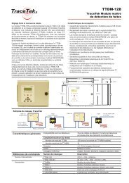
<strong>TTSIM</strong>-1<br />
Sensor Interface Module<br />
Installation/Operation Guide<br />
General Information<br />
Please read these instructions and keep them in a safe place. These<br />
instructions must be followed carefully to ensure proper operation.<br />
SHLD<br />
RS–<br />
RS+<br />
AC<br />
AC<br />
SHLD<br />
<strong>TTSIM</strong>-1<br />
Leak Location Module<br />
RATING: 24Vac ±10%<br />
50/60 Hz 3VA<br />
Network<br />
Address<br />
RS–<br />
RS+<br />
AC<br />
AC<br />
RED<br />
GRN<br />
YEL<br />
BLK<br />
GND<br />
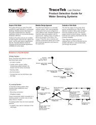
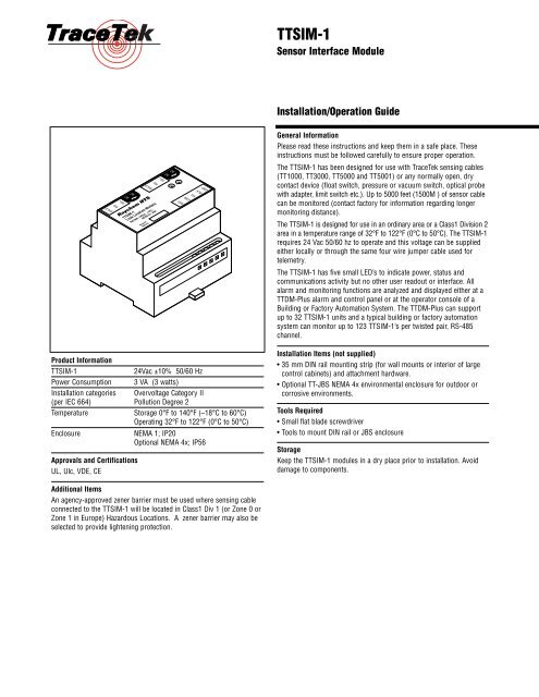
The <strong>TTSIM</strong>-1 has been designed for use with <strong>TraceTek</strong> sensing cables<br />
(TT1000, TT3000, TT5000 and TT5001) or any normally open, dry<br />
contact device (float switch, pressure or vacuum switch, optical probe<br />
with adapter, limit switch etc.). Up to 5000 feet (1500M ) of sensor cable<br />
can be monitored (contact factory for information regarding longer<br />
monitoring distance).<br />
The <strong>TTSIM</strong>-1 is designed for use in an ordinary area or a Class1 Division 2<br />
area in a temperature range of 32°F to 122°F (0°C to 50°C). The <strong>TTSIM</strong>-1<br />
requires 24 Vac 50/60 hz to operate and this voltage can be supplied<br />
either locally or through the same four wire jumper cable used for<br />
telemetry.<br />
The <strong>TTSIM</strong>-1 has five small LED’s to indicate power, status and<br />
communications activity but no other user readout or interface. All<br />
alarm and monitoring functions are analyzed and displayed either at a<br />
TTDM-Plus alarm and control panel or at the operator console of a<br />
Building or Factory Automation System. The TTDM-Plus can support<br />
up to 32 <strong>TTSIM</strong>-1 units and a typical building or factory automation<br />
system can monitor up to 123 <strong>TTSIM</strong>-1’s per twisted pair, RS-485<br />
channel.<br />
Product Information<br />
<strong>TTSIM</strong>-1<br />
24Vac ±10% 50/60 Hz<br />
Power Consumption 3 VA (3 watts)<br />
Installation categories Overvoltage Category II<br />
(per IEC 664) Pollution Degree 2<br />
Temperature<br />
Storage 0°F to 140°F (–18°C to 60°C)<br />
Operating 32°F to 122°F (0°C to 50°C)<br />
Enclosure<br />
NEMA 1; IP20<br />
Optional NEMA 4x; IP56<br />
Approvals and Certifications<br />
UL, Ulc, VDE, CE<br />
Installation Items (not supplied)<br />
• 35 mm DIN rail mounting strip (for wall mounts or interior of large<br />
control cabinets) and attachment hardware.<br />
• Optional TT-JBS NEMA 4x environmental enclosure for outdoor or<br />
corrosive environments.<br />
Tools Required<br />
• Small flat blade screwdriver<br />
• Tools to mount DIN rail or JBS enclosure<br />
Storage<br />
Keep the <strong>TTSIM</strong>-1 modules in a dry place prior to installation. Avoid<br />
damage to components.<br />
Additional Items<br />
An agency-approved zener barrier must be used where sensing cable<br />
connected to the <strong>TTSIM</strong>-1 will be located in Class1 Div 1 (or Zone 0 or<br />
Zone 1 in Europe) Hazardous Locations. A zener barrier may also be<br />
selected to provide lightening protection.
2<br />
<strong>TTSIM</strong>-1 Sensor Interface Module<br />
Installation Instructions<br />
Installing the <strong>TTSIM</strong>-1<br />
Note: To avoid damage to the <strong>TTSIM</strong>-1, store the unit in it’s packaging<br />
until ready to install.<br />
Select the mounting position.<br />
Choose a location indoors where the module will be protected from the<br />
elements, temperature extremes or heavy vibration. The <strong>TTSIM</strong>-1 is<br />
designed to be snapped onto standard 35 mm DIN rail. Existing electrical<br />
or instrumentation cabinets with spare rail space make good mounting<br />
locations. It is also possible to install a small section of DIN rail directly on<br />
a wall or cabinet surface and mount the <strong>TTSIM</strong>-1 in any location as long<br />
as it does not create a tripping hazard or expose the <strong>TTSIM</strong>-1 to impact<br />
damage. The <strong>TTSIM</strong>-1 should be mounted within 4000 feet (1200 m) wire<br />
run from the controlling TTDM-Plus or control system host. (Contact the<br />
factory for methods to increase the wire run distance beyond 4000 feet).<br />
Important: The <strong>TTSIM</strong>-1 is an electronic unit. Take the following<br />
precautions to avoid damage to electronic components:<br />
• Handle with care, avoid mechanical shock and impact.<br />
• Keep dry.<br />
• Avoid exposure to static electricity by touching a nearby piece of<br />
grounded equipment or water pipe prior to handling the <strong>TTSIM</strong>-1.<br />
• Avoid contact with metal filings, grease, pipe dope and other contaminants.<br />
Mounting the <strong>TTSIM</strong>-1 module (without NEMA 4x Enclosure)<br />
• Secure a 6" (15 cm) length of DIN rail to the desired mounting surface,<br />
or locate an existing DIN rail with sufficient space to install the <strong>TTSIM</strong>-1.<br />
• Remove the <strong>TTSIM</strong>-1 from it’s packaging and snap onto the DIN rail<br />
with the release tab towards the bottom.<br />
• Note: When properly oriented, there will be two terminal strips on the<br />
top of the module and one on the bottom. See Figure 1.<br />
Mounting the <strong>TTSIM</strong>-1 module in the optional NEMA-4X enclosure<br />
• The TT-JBS enclosure is available either pre-drilled for 3/4" conduit<br />
fittings or without any pre-drilled holes.<br />
• Plan conduit alignment and drill holes if necessary.<br />
• A typical outdoor or harsh environment installation will require three holes<br />
in the JBS: one for inbound power and telemetry, one for outbound power<br />
and telemetry and one for the sensor cable leader. See Figure 2.<br />
• Secure the TT-JBS to any convenient vertical surface using the four<br />
corner mounting holes and hardware suitable for the selected surface.<br />
• Rough-in conduit as required and pull 4 x 18AWG shielded jumper wire<br />
for power and telemetry. Leave approximately 8" (20cm) for connections.<br />
Pull in the leader cable to the sensor circuit through the bottom fitting.<br />
• In order to provide the maximum ESD protection, and to be CE<br />
compliant, the DIN rail must be grounded.<br />
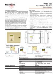
Figure 1. DIN Rail Mount<br />
13 14 15 16 17 20 21 22 23 24<br />
SHLD<br />
RS–<br />
RS+<br />
AC<br />
AC<br />
<strong>TTSIM</strong>-1<br />
Leak Location Module<br />
RATING: 24Vac ±10%<br />
50/60 Hz 3VA<br />
Network<br />
Address<br />
SHLD<br />
RED<br />
RS–<br />
GRN<br />
RS+<br />
YEL<br />
AC<br />
BLK<br />
AC<br />
GND<br />
8 9 10 11 12<br />
13 14 15 16 17 20 21 22 23 24<br />
SHLD<br />
RS–<br />
RS+<br />
AC<br />
AC<br />
<strong>TTSIM</strong>-1<br />
Leak Location Module<br />
RATING: 24Vac ±10%<br />
50/60 Hz 3VA<br />
Network<br />
Address<br />
SHLD<br />
RED<br />
RS–<br />
GRN<br />
RS+<br />
YEL<br />
AC<br />
AC<br />
BLK<br />
GND<br />
8 9 10 11 12<br />
Figure 2. NEMA 4x Enclosure
3<br />
<strong>TTSIM</strong>-1 Sensor Interface Module<br />
Installation Instructions<br />
Note: Rough-in and final connections do not have to be completed at<br />
the same time, however make sure to replace the cover and tighten the<br />
cover screws if the JBS box will be left in a partially installed condition<br />
overnight or longer.<br />
TTDM-<br />
Plus<br />
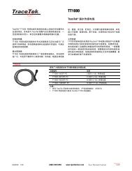
Power Supply Options:<br />
The <strong>TTSIM</strong>-1 units require 24 Vac ±10% 50/60 Hz. In most networks<br />
the operating voltage will be supplied from a step down transformer<br />
mounted near the TTDM-Plus alarm panel or PLC. Figure 3 shows typical<br />
wiring adequate for any network that will be monitored by a TTDM-<br />
Plus. For very large networks or very long telemetry cable runs, there<br />
may be too much voltage drop in the power/telemetry cable to power<br />
the entire network from one location. In those situations, a second<br />
transformer at the distant end of the system will be required. Be sure that<br />
each <strong>TTSIM</strong>-1 receives operating voltage from one and only one source.<br />
Line<br />
voltage<br />
XFMR<br />
24 Vac<br />
SIM<br />
SIM<br />
SIM<br />
SIM<br />
SIM<br />
SIM<br />
SIM<br />
Connections for Power and Telemetry<br />
<strong>TTSIM</strong>-1 communicates all alarm and status messages via RS-485<br />
twisted pair telemetry. Two of the four conductors in the power/telemetry<br />
cable are used for telemetry and the other two wire are used to run the<br />
operating voltage. Belden P/N 8722 is a good choice.<br />
For all <strong>TTSIM</strong>-1 modules except the last one, there will be an incoming<br />
cable (from the TTDM-Plus or other host system) and an outgoing<br />
cable (toward the next <strong>TTSIM</strong>-1).<br />
Strip back a sufficient amount of the jacket insulation and shielding to<br />
expose about 1" (2.5 cm) of the four primary colored wires. The<br />
preferred color code is red, black, green, white plus a shield drain wire,<br />
however any color code is acceptable as long as the installer is consistent<br />
with the intent of these instructions. See Figure 4.<br />
Strip the primary wires to expose approximately 1/4" (6 mm) of conductor<br />
and make the following connections:<br />
Terminal Color Item<br />
13 — Shield Drain Wire<br />
14 Blk RS-485 (–)<br />
15 Red RS-485 (+)<br />
16 Grn 24 Vac (no polarity)<br />
17 Wht 24 Vac (no polarity)<br />
Figure 3. Power Supply to SIM units<br />
13 14 15 16 17 20 21 22 23 24<br />
SHLD<br />
RS–<br />
Figure 4. Power and Telemetry Connections<br />
RS+<br />
AC<br />
AC<br />
<strong>TTSIM</strong>-1<br />
Leak Location Module<br />
RATING: 24Vac ±10%<br />
50/60 Hz 3VA<br />
SHLD<br />
RS–<br />
RS+<br />
AC<br />
AC<br />
20 — Shield Drain Wire<br />
21 Blk RS-485 (–)<br />
22 Red RS-485 (+)<br />
23 Grn 24 Vac (no polarity)<br />
24 Wht 24 Vac (no polarity)<br />
Special Note for the last <strong>TTSIM</strong>-1 in the chain:<br />
The RS-485 network will perform better if the twisted pair telemetry is<br />
properly terminated at the last <strong>TTSIM</strong>-1 in the network. There are two<br />
jumper pins that should be shorted with a jumper block as shown in<br />
Figure 5.<br />
16 17 20 21<br />
Figure 5. End of Line Jumper Block
4<br />
<strong>TTSIM</strong>-1 Sensor Interface Module<br />
Installation Instructions<br />
Leader Cable Connections for Sensor Cable<br />
<strong>TTSIM</strong>-1 can be used with any of the <strong>TraceTek</strong> family of sensor cables<br />
including: TT1000, TT3000, TT5000 and TT5001. Connect the leader<br />
cable to the sensor as shown in Figure 6.<br />
<strong>TTSIM</strong>-1<br />
Leak Location Module<br />
RATING: 24Vac ±10%<br />
50/60 Hz 3VA<br />
Network<br />
Address<br />
RED<br />
GRN<br />
YEL<br />
BLK<br />
GND<br />
8 9 10 11 12<br />
Terminal Color Item<br />
8 Red<br />
Red / Green Sensor Cable Loop<br />
9 Grn<br />
10 Yel<br />
Yellow /Black Sensor Cable Loop<br />
11 Blk<br />
12 — Wire to local ground point (optional)<br />
Figure 6. Sensing Cable Connections<br />
Leader Cable Connections for Float Switches and Other Open Contact<br />
Devices<br />
The <strong>TTSIM</strong>-1 can monitor any open contact device that generates a<br />
contact closure when an alarm condition occurs. Typically this device<br />
will be a float switch, a pressure switch, a limit switch or any similar<br />
on/off sensor. Connect the leader to the normally open contacts of the<br />
sensing device as shown in Figure 7.<br />
<strong>TTSIM</strong>-1<br />
Leak Location Module<br />
RATING: 24Vac ±10%<br />
50/60 Hz 3VA<br />
Network<br />
Address<br />
RED<br />
GRN<br />
YEL<br />
BLK<br />
GND<br />
8 9 10 11 12<br />
Terminal Color Item<br />
8 Red Twist red and green wires together at the switch device<br />
9 Grn and connect to the N.O contact<br />
10 Yel Twist yellow and black wires together at the<br />
11 Blk switch device and connect to the C contact<br />
12 — No connection<br />
Any normally<br />
open switch<br />
sensor device<br />
RED/GRN<br />
N. O.<br />
YEL/BLK<br />
C.<br />
Operating Instructions<br />
Figure 7 Switch Type Sensor<br />
Network Address Assignment<br />
All <strong>TTSIM</strong>-1 units are shipped from the factory with their network address<br />
pre-set to a value above the normal range of valid addresses. This allows<br />
the network of <strong>TTSIM</strong>-1 units to be simultaneously powered during the<br />
start-up process without the possibility of address conflicts. However,<br />
each <strong>TTSIM</strong>-1 unit requires a unique address before it can communicate<br />
with the TTDM-Plus or other host. A jumper block is provided adjacent<br />
to Terminal 8 as shown in Figure 8. When the jumper clip is positioned as<br />
shown, the <strong>TTSIM</strong>-1 is temporarily forced to address 0. With the address<br />
forced to 0, the TTDM-Plus panel can be used to assign a permanent<br />
address in the valid range of 1 to 31. After the permanent address is<br />
assigned, the jumper clip is removed and the process is repeated for the<br />
next SIM in the network. Typically, the sensor interface card inside the<br />
TTDM-Plus is assigned address 1, so the first <strong>TTSIM</strong>-1 in the network is<br />
assigned with address 2, the next address 3 and so on.<br />
When a PLC or other generic host system hosts the <strong>TTSIM</strong>-1 network,<br />
the host determines the valid address range. The <strong>TTSIM</strong>-1 can be<br />
assigned to any address from 0 to 255 (decimal) (00 to FF hex).<br />
The assigned address is stored in the modbus register 40011 (see page 7).<br />
Figure 8. Configuration Jumper in Position<br />
8 9 10
5<br />
<strong>TTSIM</strong>-1 Sensor Interface Module<br />
Installation Instructions<br />
<strong>TTSIM</strong>-1 Reset<br />
In the event that the <strong>TTSIM</strong>-1 appears to be hung-up and unresponsive<br />
to the network it is possible to force a system reset. To force a RESET<br />
of the <strong>TTSIM</strong>-1 processor, use a small flat blade screwdriver to<br />
momentarily short the pads shown in Figure 9.<br />
Reset pads<br />
8 12<br />
Maintenance and Troubleshooting<br />
No user maintenance is required! There are no user adjustments or<br />
calibrations that can be performed in the field.<br />
Each <strong>TTSIM</strong>-1 is tested and calibrated in the factory at production time<br />
through the test header. An operating <strong>TTSIM</strong>-1 runs a continuous self<br />
check routine and reports any discrepancies to the host TTDM-Plus or<br />
PLC. If the <strong>TTSIM</strong>-1 or the network wiring fails is such a way that the<br />
<strong>TTSIM</strong>-1 cannot communicate with the host, then the host reports the<br />
failure as a communications failure.<br />
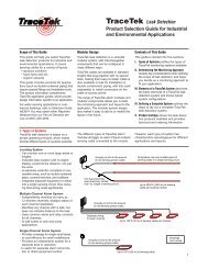
Status Indicators<br />
There are 5 LED’s on the <strong>TTSIM</strong>-1 circuit board to indicate: operating<br />
power, communications (inbound and outbound), sensor status (leak<br />
detected and trouble). See Figure 10 for locations and colors<br />
Table 1 indicates various status conditions and possible corrective actions:<br />
Figure 9. Reset Pads<br />
TX (Yellow)<br />
Power (Green)<br />
RX (Yellow)<br />
13 14 15 16 17 20 21 22 23 24<br />
SHLD<br />
RS–<br />
RS+<br />
AC<br />
AC<br />
<strong>TTSIM</strong>-1<br />
Leak Location Module<br />
RATING: 24Vac ±10%<br />
50/60 Hz 3VA<br />
Network<br />
Address<br />
SHLD<br />
RED<br />
RS–<br />
GRN<br />
RS+<br />
YEL<br />
AC<br />
BLK<br />
AC<br />
GND<br />
Service (Yellow)<br />
Alarm (Red)<br />
8 9 10 11 12<br />
Figure 10. LED Locations<br />
Table 1. <strong>TTSIM</strong>-1 LED Status Indications<br />
POWER TX RX ALARM SERVICE INDICATION<br />
OFF OFF OFF OFF OFF No power to unit. Check wiring, connections and power supply.<br />
Measure voltage at pins 16 and 17. Should be 24 Vac ±10%.<br />
ON FLASHING FLASHING SLOW FLASH OFF Normal Operation. No alarms or service requests.<br />
Alarm LED flashes once every 5 seconds to indicate normally<br />
operating microprocessor.<br />
ON FLASHING FLASHING ON OFF Leak detected by sensor cable or switch type device. Check<br />
location being monitored for leak or spill.<br />
ON FLASHING FLASHING OFF FLASHING SIM unit has detected a condition requiring outside attention.<br />
Flash Code:<br />
1 Sensor cable break<br />
2 Sensor cable loop imbalance<br />
3 EPROM hardware error<br />
10 Sensor cable contamination<br />
ON OFF FLASHING SLOW FLASH OFF SIM unit is not responding to network master unit. Use INIT SIM<br />
Network command on TTDM-Plus and/or use configuration jumper<br />
to force SIM address to zero then, re-address to an unused<br />
address.<br />
ON OFF OFF OFF OFF SIM unit not receiving any communication from network master<br />
unit. Check other SIM units for flashing RX light, if none seen, then<br />
check wiring at network master unit or intermediate wiring and<br />
connections.
6<br />
<strong>TTSIM</strong>-1 Sensor Interface Module<br />
Operation Instructions<br />
<strong>TTSIM</strong>-1 Modbus Implementation<br />
<strong>TTSIM</strong>-1 uses two wire, RS-485, full duplex, no hardware handshaking at 9600 baud. The <strong>TTSIM</strong>-1 software is able to distinguish between three different<br />
communication protocols and respond automatically in the mode being used by the host system. The three supported protocols are: Modbus-ASCII,<br />
Modbus-RTU, and a proprietary version of Opto22 (automatically invoked when the host is a TTDM-Plus). System integrators choosing to communicate<br />
directly with the <strong>TTSIM</strong>-1 are free to use either Modbus-ASCII or Modbus-RTU using the registers listed in the following tables.<br />
Node addressing: All <strong>TTSIM</strong>-1 units are shipped from the factory with address set to 199. New <strong>TTSIM</strong>-1 units must be added to a network one at<br />
a time and immediately re-addressed to a unique unused address. Alternatively, the <strong>TTSIM</strong>-1’s can be pre-addressed by the <strong>TraceTek</strong> distributor<br />
using a TTDM-Plus panel. If for some reason a <strong>TTSIM</strong>-1 has been assigned an unknown address, it can be temporarily forced to 0 by installing<br />
Configuration Jumper (See Figure 8) . With this jumper in place the <strong>TTSIM</strong>-1 will respond to node address 0 and a new unique address can then<br />
be loaded in register 40011. After the configuration jumper is removed the address loaded in 40011 will take precedence.<br />
Note: In the following tables those registers in bold type are the most likely registers to be used by system integrators. All registers are documented<br />
but many are used only for factory calibration or internal system monitoring.<br />
Table 2. Analog Input Registers<br />
Modbus<br />
Register Name Description Units Range<br />
30001 Status Word Bit level status flags, (see Table 4.) None 0-65535<br />
30002 Location Resistance Location of leak or contamination when detection is above current thresh. Ohms 0-65535<br />
30003 Detection resistance Resistance through the leak or contamination Kohms 0-65535<br />
30004 Detection Current Current flowing through leak or contamination 0.1 micro-amps 0-65535<br />
30005 RG Resistance Loop resistance red to green Ohms 0-65535<br />
30006 YB Resistance Loop resistance yellow to black Ohms 0-65535<br />
30007 ADC Counts1 Adc count of V1 (internal value) count 0-65535<br />
30008 ADC Counts2 Adc count of V2 (internal value) count 0-65535<br />
30009 ADC Counts3 Adc count of V3 (internal value) count 0-65535<br />
30010 F/W version Firmware version V x.xx none 0-65535<br />
30011 Product ID Product ID number none 0-65535<br />
30012 EEPROM Checksum Check sum none 0-65535<br />
30013 Voltage Step Size Step size in ohms (internal value) ohms 0-65535<br />
Table 3. Analog Output Registers<br />
Modbus<br />
Register Name Description Units Range<br />
40001 SIM Operating Mode 0: normal, 8 normal w/no off time, 64: detect Earth to RG loop, None 0 - 4095<br />
72 detect Earth to YB loop [0 default]<br />
40002 Leak Resistance Leak alarm is triggered when resistance is less than or equal to Kohms 0 - 4095<br />
Threshold<br />
[18 default]<br />
40003 Service Current Service alarm is triggered when current is greater than or equal to 0.1 micro-amps 0 - 4095<br />
Threshold<br />
[500 default]<br />
40004 Sensor Delta Maximum difference in percent between RG loop percent 0 - 4095<br />
Threshold resistance and YB loop resistance [25 default]<br />
40005 Rref Reference resistance minus offset of 6000 Ohms 0 - 4095<br />
(Factory calibration value)<br />
[2020 default]<br />
40006 K Op Amp Gain correction none 0 - 4095<br />
(Factory calibration value)<br />
[2000 default]<br />
40007 Vref A/D reference voltage mVolts 0 - 4095<br />
(Factory calibration value)<br />
[2500 default]<br />
40008 Settling Time Settling time before making A/D measurements mSec 0 - 255<br />
[50 default]<br />
40009 Cycle Time Seconds of measurement cycle plus off-time Sec 0-655<br />
5 default]
7<br />
<strong>TTSIM</strong>-1 Sensor Interface Module<br />
Operation Instructions<br />
40010 Cycles per Polarity Number of cycles before alternating polarity count 0 - 4095<br />
0 default]<br />
40011 Node Address RS485 node address none 0 - 255<br />
[0 default]<br />
40012 High Voltage YB loop resistance above which high voltage mode is automatically selected Ohms x 10 0 - 4095<br />
Threshold<br />
[800 default]<br />
40013 - Misc. Flags, Calibration and mode controls used during calibration. -RESERVED none<br />
40020 Gain setting<br />
40021 EEPROM Check Checksum for EEPROM None varies<br />
Table 4 Status Word Flags (Register 30001)<br />
Data is returned from register 300001 as four hexadecimal digits<br />
Bit<br />
Description<br />
00 1: detection resistance below high current threshold<br />
01 1: current is above locating current threshold<br />
02 1: open of high resistance in sensor loop(s)<br />
03 1: difference / average of loop resistance > delta threshold<br />
04 1: EEPROM read error<br />
05 1: EEPROM write error<br />
06 1: EEPROM verify error<br />
07 1: EEPROM type X24C01A or equivalent 0: EEPROM type X24C01<br />
08 1: low voltage used 0: high voltage used<br />
09 1: low current used 0: high current used<br />
10 1: measurement cycle in progress 0: off time<br />
11 1: reverse polarity mode 0: normal polarity mode<br />
12 1: ADC calibrate disabled 0: ADC Calibrate enabled<br />
13- 15 Spare (always 0)
8<br />
<strong>TTSIM</strong>-1 Sensor Interface Module<br />
Operation Instructions<br />
System Integration Guidelines<br />
The system integrator has three main responsibilities: Assuring proper communications, monitoring for hardware failures and interpretation of<br />
detection parameters.<br />
Communicating with the <strong>TTSIM</strong>-1 requires that the node address at 40011 be set to a unique value for each <strong>TTSIM</strong>-1 on the network. The TTDM-Plus<br />
has a specific function to do this at MENU | SIM NETWORK | SIM ADDRESS. Assuming that any newly added <strong>TTSIM</strong>-1 is forced to 0 with the configuration<br />
jumper as shown in Figure 8 then the TTDM-Plus can be used to assign any new unused address. For systems hosted by the TTDM-Plus the<br />
range of acceptable is 0 - 31, for systems hosted by the older TTDM-NMM the acceptable range of addresses is 0 - 15. System that will be hosted by a<br />
generic modbus host (PLC’s DCS’s BMS etc) will typically be limited by the address space specification of the generic host or to the maximum range of<br />
the <strong>TTSIM</strong>-1 of 0 - 255. When configuring the address of a <strong>TTSIM</strong>-1 using a generic host the <strong>TTSIM</strong>-1 unit can be forced to zero with the configuration<br />
jumper (See Figure 8) then while responding to address 0, a new address can be written to register 40011. After the configuration jumper is<br />
removed, the <strong>TTSIM</strong>-1 unit will respond to the address set in register 40011.<br />
Important Note: Interpretation of leak parameters and location calculations are entirely automatic when the system is hosted by a TTDM-Plus.<br />
The following paragraphs apply to <strong>TTSIM</strong>-1 networks managed directly by a generic modbus host system.<br />
Status Check: Register 30001 should be scanned for a “1” in bit locations 02 and 03. A “1” bit in either one of these locations indicates physical<br />
problems with the sensor cable that need to be addressed by the maintenance staff.<br />
Interpreting the leak parameters is driven by the values in three registers: 30002, 30003 and 30004. Resistance through the leak is reported in 30003.<br />
A clean and dry sensor cable or an open float switch will report back the maximum value of 65535. Progressively lower resistances and higher currents<br />
(as seen in register 30004) are the signatures of a detected leak. The following table gives some guidance in interpreting the leak parameters.<br />
Table 5. Leak Parameters<br />
Sensor / Cable Type Normal Conditions Leak Detected Sensor Contamination<br />
TT1000/ TT3000 water or 30003 > 1000 K Ohms 30003 < 18 K Ohms 30003 < 200K Ohms<br />
water based fluids 30004 < 5 micro amps 30004 > 200 micro amps 30004 > 50 micro amps<br />
TT5000 / TT5001 fuels 30003 > 1000 K Ohms 30003 < 5 K ohms Usually not applicable,<br />
or solvents 30004 < 5 micro amps 30004 > 250 micro amps Values similar to TT1000/TT3000<br />
may indicate water intrusion<br />
Float Switch or other normally 30003 > 1000 K Ohms 30003 < 1 K ohms N/A<br />
open contact device 30004 < 5 micro amps 30004 > 250 micro amps<br />
Calculating Leak Location: For sensor cables (TT1000, TT3000, TT5000, and TT5001) the value reported in register 30002 is the resistance<br />
measurement between the <strong>TTSIM</strong>-1 module and the leak location in ohms.<br />
Subtract any known added-in resistance such as that of a zener barrier or very long leader cable runs.<br />
The resulting value can then be scaled to engineering units as follows:<br />
For feet: divide corrected value from register 30002 by 3.90<br />
For meters: divide the corrected value from register 30002 by 12.796<br />
© 2001 Raychem HTS Printed in USA (10195) H56830 01/01<br />
Raychem HTS<br />
300 Constitution Drive<br />
Menlo Park, CA 94025-1164<br />
Tel (800) 545-6258<br />
Fax (650) 474-7711<br />
Fax-on-Demand (800) 329-4494<br />
info@raychemhts.com<br />
www.tracetek.com<br />
Important: All information, including illustrations, is believed to be reliable. Users, however, should independently<br />
evaluate the suitability of each product for their application. Raychem HTS makes no warranties as to the accuracy or<br />
completeness of the information, and disclaims any liability regarding its use. Raychem HTS’s only obligations are<br />
those in the Raychem HTS Standard Terms and Conditions of Sale for this product, and in no case will Raychem HTS<br />
or its distributors be liable for any incidental, indirect, or consequential damages arising from the sale, resale, use, or<br />
misuse of the product. Specifications are subject to change without notice. In addition, Raychem HTS reserves the<br />
right to make changes—without notification to Buyer—to processing or materials that do not affect compliance with<br />
any applicable specification.