TraceTek TT3000 and TT5000 Series Modular Sensing Cables
TraceTek TT3000 and TT5000 Series Modular Sensing Cables
TraceTek TT3000 and TT5000 Series Modular Sensing Cables

Create successful ePaper yourself
Turn your PDF publications into a flip-book with our unique Google optimized e-Paper software.
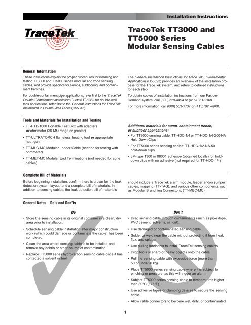
Installation Instructions<br />
<strong>TraceTek</strong> <strong>TT3000</strong> <strong>and</strong><br />
<strong>TT5000</strong> <strong>Series</strong><br />
<strong>Modular</strong> <strong>Sensing</strong> <strong>Cables</strong><br />
General Information<br />
These instructions explain the proper procedures for installing <strong>and</strong><br />
testing <strong>TT3000</strong> <strong>and</strong> <strong>TT5000</strong> series modular <strong>and</strong> zone sensing<br />
cables, <strong>and</strong> provide specifics for sumps, subflooring, <strong>and</strong> containment<br />
trenches.<br />
For double-containment pipe applications, refer first to the <strong>TraceTek</strong><br />
Double-Containment Installation Guide (LIT-138); for double-wall<br />
tank applications, refer first to the General Instructions for <strong>TraceTek</strong><br />
Installation in Double-Wall Tanks (H55313).<br />
The General Installation Instructions for <strong>TraceTek</strong> Environmental<br />
Applications (H55523) provides an overview of the installation process<br />
for the <strong>TraceTek</strong> system, <strong>and</strong> refers to detailed instructions<br />
for each step.<br />
To obtain copies of installation instructions from our Fax-on-<br />
Dem<strong>and</strong> system, dial (800) 329-4494 or (415) 361-2168.<br />
For more information, call (800) 553-1737 or (415) 361-4900.<br />
Tools <strong>and</strong> Materials for Installation <strong>and</strong> Testing<br />
• TT-PTB-1000 Portable Test Box with adapters<br />
or ohmmeter (20-MΩ range or greater)<br />
• TT-ULTRATORCH flameless heating tool or appropriate<br />
heat gun.<br />
• TT-MLC-MC <strong>Modular</strong> Leader Cable (needed for testing with<br />
ohmmeter)<br />
• TT-MET-MC <strong>Modular</strong> End Terminations (not needed for zone<br />
cables)<br />
Additional materials for sump, containment trench,<br />
or subfloor applications:<br />
• For <strong>TT3000</strong> sensing cable: TT-HDC-1/4 or TT-HDC-1/4-200-NA<br />
Hold-Down Clips<br />
• For <strong>TT5000</strong> series sensing cables: TT-HDC-1/2-NA-50<br />
hold-down clips<br />
• 3M-type 1300 or 08001 adhesive (obtained locally) for holddown<br />
clips with no adhesive (not required for TT-HDC-1/4)<br />
Complete Bill of Materials<br />
Before beginning installation, confirm there is a plan for the leak<br />
detection system layout, <strong>and</strong> a complete bill of materials. In<br />
addition to sensing cables, the leak detection bill of materials<br />
should include a <strong>TraceTek</strong> alarm module, leader <strong>and</strong>/or jumper<br />
cables, mapping (TT-TAG), <strong>and</strong> various other components, such<br />
as <strong>Modular</strong> Branching Connectors, (TT-MBC-MC).<br />
General Notes—Do’s <strong>and</strong> Don’ts<br />
Do<br />
• Store the sensing cable in its original container in a clean, dry<br />
area prior to installation.<br />
• Schedule sensing cable installation after major construction<br />
work (which could damage or contaminate the cable) has been<br />
completed.<br />
• Clean the area where sensing cable is to be installed <strong>and</strong><br />
remove any debris or other source of contamination.<br />
• Replace <strong>TT5000</strong> series hydrocarbon sensing cable once it has<br />
contacted a solvent or fuel.<br />
Don’t<br />
• Drag sensing cable through contaminants (such as pipe dope,<br />
PVC cement, solvents, oil, dirt).<br />
• Use damaged or contaminated sensing cable.<br />
• Solder or weld near the cable without protecting it from heat,<br />
flux, <strong>and</strong> splatter.<br />
• Use pulling lubricants to install <strong>TraceTek</strong> sensing cables.<br />
• Drop tools or sharp or heavy objects onto the cable.<br />
• Pull the sensing cable with excessive force (more than<br />
50 pounds/20 kg).<br />
• Place <strong>TT5000</strong> series sensing cable where it is subject to<br />
pinching or pressure, as this will trigger an alarm.<br />
• Subject <strong>TT5000</strong> series sensing cable to temperatures higher<br />
than 80°C (176°F).<br />
• Use adhesive tapes or clamping devices to secure the sensing<br />
cable.<br />
• Allow cable connectors to become wet, dirty, or contaminated.<br />
1
Installation Instructions for <strong>TT3000</strong> <strong>and</strong> <strong>TT5000</strong> <strong>Series</strong> <strong>Modular</strong> <strong>Sensing</strong> <strong>Cables</strong><br />
General Layout of <strong>TraceTek</strong> System<br />
<strong>Modular</strong> branching connector<br />
(TT-MBC-MC)<br />
<strong>Modular</strong> jumper cable<br />
<strong>Modular</strong> sensing cable<br />
<strong>Modular</strong> leader cable<br />
(TT-MLC-MC)<br />
<strong>TraceTek</strong> alarm<br />
module (several<br />
models available;<br />
TTDM alarm <strong>and</strong><br />
locating module<br />
is shown)<br />
<strong>Modular</strong> jumper cable<br />
(TT-MJC-xxx-MC)<br />
<strong>Modular</strong> end termination<br />
(TT-MET-MC)<br />
<strong>Modular</strong><br />
sensing<br />
cable<br />
Note:<br />
• Drawing not to scale.<br />
• Not shown: heat-shrinkable tube<br />
to cover each connection.<br />
Hold-down clip<br />
(TT-HDC)<br />
<strong>TraceTek</strong> tag<br />
(TT-TAG)<br />
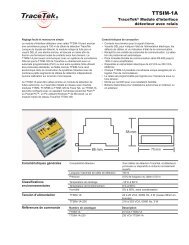
<strong>Modular</strong> <strong>Sensing</strong> Cable<br />
(with factory-installed connectors)<br />
Factory-installed connector<br />
Heat-shrinkable tube supplied with cable<br />
(for extras, order TT-HIEX-2)<br />
<strong>Modular</strong> sensing cable<br />
(<strong>TT3000</strong>-xxx-MC or<br />
<strong>TT5000</strong>-xxx-MC or<br />
TT5001-xxx-MC)<br />
<strong>Modular</strong> end termaination<br />
TT-MET-MC<br />
Zone <strong>Sensing</strong> Cable<br />
(with factory-installed connector <strong>and</strong> end termination)<br />
Factory-installed connector<br />
Factory-installed<br />
end termination<br />
Heat-shrinkable tube supplied with cable<br />
(for extras, order TT-HIEX-2)<br />
<strong>Modular</strong> sensing cable<br />
(<strong>TT3000</strong>-ZONE-MC or<br />
<strong>TT5000</strong>-ZONE-MC or<br />
TT5001-ZONE-MC)<br />
2
Installation Instructions for <strong>TT3000</strong> <strong>and</strong> <strong>TT5000</strong> <strong>Series</strong> <strong>Modular</strong> <strong>Sensing</strong> <strong>Cables</strong><br />
Installation Steps<br />
1. Prepare the area where the sensing cable will be located.<br />
• Verify that major construction is complete.<br />
• Clean the area where the cable will be installed to remove<br />
debris <strong>and</strong> sources of contamination. For techniques in<br />
double-containment piping, consult the <strong>TraceTek</strong> Double-<br />
Containment Installation Guide (LIT-138).<br />
• For sumps, containment trenches, <strong>and</strong> subfloor applications,<br />
install <strong>TraceTek</strong> hold-down clips. For <strong>TraceTek</strong> <strong>TT3000</strong> sensing<br />
cables, use 1/4" hold-down clips (TT-HDC-1⁄4...); for<br />
<strong>TraceTek</strong> <strong>TT5000</strong> series sensing cables, use 1/2" hold-down<br />
clips (TT-HDC-1⁄2-NA-50).<br />
Clean the floor surface where hold-down clips will be placed<br />
so adhesive can work properly.<br />
Position hold-down clips so the sensing cable will provide the<br />
desired leak detection coverage. To best secure the cable,<br />
alternate the direction of the hold-down clips, <strong>and</strong> install them<br />
at intervals of no greater than 6 feet (2 m) <strong>and</strong> at every<br />
change in direction (at sides of trench, for example).<br />
Important: Let the adhesive dry per manufacturer’s recommendation<br />
before proceeding with sensing-cable installation.<br />
• In sumps that may collect water, mount <strong>TT5000</strong> series sensing<br />
cable vertically to allow it to detect hydrocarbons floating<br />
on water; prepare for this by installing hold-down clips up<br />
side of sump.<br />
TT-HDC-1⁄4<br />
or<br />
TT-HDC-1⁄4-200-NA<br />
< 6 ft (2 m)<br />
TT-HDC-1⁄2-NA-50<br />
2. Check each length of sensing cable before installation.<br />
To ensure that each length of sensing cable is intact <strong>and</strong> free of contamination,<br />
follow the <strong>Sensing</strong> Cable Test Procedure detailed on<br />
page 6. Do not use damaged or contaminated sensing cable.<br />
3. Observe proper precautions when h<strong>and</strong>ling sensing cables.<br />
Observe the do’s <strong>and</strong> don’ts under “General Notes” on page 1 of<br />
these instructions; take care to avoid damaging or contaminating<br />
sensing cable.<br />
3
Installation Instructions for <strong>TT3000</strong> <strong>and</strong> <strong>TT5000</strong> <strong>Series</strong> <strong>Modular</strong> <strong>Sensing</strong> <strong>Cables</strong><br />
Installation Steps (continued)<br />
4. Connect, orient, install, <strong>and</strong> test each length of sensing cable in sequence.<br />
1. Connect a <strong>Modular</strong> End Termination (TT-MET-MC) to the first<br />
sensing-cable length to be installed.<br />
Note: This step is not required for a zone sensing cable, which<br />
has a factory-installed end termination.<br />
If installing modular sensing cable in double-contained piping,<br />
refer to the <strong>TraceTek</strong> Double-Containment Installation Guide<br />
(LIT-138) for detailed instructions.<br />
2. Orient sensing cable so end termination will be away from<br />
connection to the <strong>TraceTek</strong> alarm module. Work out from the<br />
alarm module connection. For sensing cable on reels (lengths<br />
over 10 feet), put the reel on an axle <strong>and</strong> pull the cable out.<br />
Connector with pins<br />
toward module<br />
3. Install sensing cable in accordance with the leak detection<br />
layout plan.<br />
For sumps, containment trenches, <strong>and</strong> subfloor applications,<br />
pull the cable alongside the installed hold-down clips; minimum<br />
bend radius is 2" (50 mm). Leave 6" (150 mm) of sensing<br />
cable on each end for the connector service loop.<br />
Important: Verify that the adhesive securing the hold-down<br />
clips has dried; liquid adhesive must not contact the cable.<br />
Push sensing cable into the hold-down clips <strong>and</strong> position the<br />
sensing cable to lay flat on the surface to be monitored.<br />
In sumps that may collect water, mount at least a portion of<br />
<strong>TT5000</strong> series cable vertically.<br />
Be sure not to leave <strong>TT5000</strong> series cable so it may be kinked,<br />
pinched, or subjected to pressure, as this may trigger an alarm.<br />
4. Test each length of sensing cable after installing it <strong>and</strong><br />
before attaching it to cable already installed. Confirm that the<br />
sensing cable is clean <strong>and</strong> intact by following the <strong>Sensing</strong><br />
Cable Test Procedure detailed on page 6.<br />
5. Connect the sensing cable to the cable string (lengths of<br />
sensing cable connected in series) previously installed;<br />
before making connection push heat-shrinkable tube onto<br />
sensing cable.<br />
Note: If installing sensing cable in a double-wall tank or<br />
other inaccessible location, the heat-shrinkable tube must be<br />
shrunk down before installation; see step 5 on page 5 for<br />
instructions.<br />
For sumps, containment trenches, <strong>and</strong> subfloor applications:<br />
• Leave a service loop at each connector as shown.<br />
• Mark the connector position on the layout plan.<br />
• Install <strong>TraceTek</strong> mapping tag (TT-TAG).<br />
Note: As an extra precaution on large installations, periodically<br />
test the entire cable string to confirm that all installed<br />
sensing cable is still clean <strong>and</strong> intact.<br />
Unplug the end termination <strong>and</strong> connect it to the next length<br />
of sensing cable to be installed.<br />
Repeat the installation sequence for each length of cable.<br />
Service<br />
loop<br />
R <strong>TraceTek</strong><br />
Systems<br />
4
Installation Instructions for <strong>TT3000</strong> <strong>and</strong> <strong>TT5000</strong> <strong>Series</strong> <strong>Modular</strong> <strong>Sensing</strong> <strong>Cables</strong><br />
Installation Steps (continued)<br />
5. Complete the system.<br />
• Install other <strong>TraceTek</strong> components (such as <strong>Modular</strong><br />
Branching Connectors, Weighted Lengths, <strong>and</strong> <strong>Modular</strong><br />
Jumper <strong>Cables</strong>) as called for in the system layout. Complete<br />
the sensing circuit.<br />
Connector<br />
with pins<br />
toward module<br />
<strong>Modular</strong> Branching Connector<br />
(shows after middle leg)<br />
Middle leg (shows first on map)<br />
• Test the sensing circuit (or portions of it) to confirm that the<br />
sensing cable is clean <strong>and</strong> intact. Follow the <strong>Sensing</strong> Cable<br />
Test Procedure detailed on page 6.<br />
• Install heat-shrinkable tubes over all mated male/female<br />
(pin/socket) connections<br />
— Move the heat-shrinkable tube along the sensing cable<br />
until it is centered over the mated connection.<br />
— Using a heat gun or Ultratorch, shrink the tube over the<br />
connection. Begin in the center <strong>and</strong> shrink toward each<br />
end until tube fully conforms to the shape of the connection.<br />
Note: If a heat-shrinkable tube must be removed (for<br />
example, for cable testing), refer to Oversleeve Removal<br />
Instructions (H54258), Fax-on-Dem<strong>and</strong> ID 54258.<br />
• Connect the sensing circuit to the <strong>TraceTek</strong> alarm module <strong>and</strong><br />
activate the system as soon as is practical. Use the module to<br />
monitor for events during the final stages of construction.<br />
6. Take precautions if installation is incomplete at end of work day.<br />
At the end of the work day:<br />
• Ensure that there are no exposed connectors. Each sensing<br />
cable should be connected to a <strong>Modular</strong> Leader Cable (TT-<br />
MLC-MC), <strong>Modular</strong> End Termination (TT-MET-MC), <strong>and</strong>/or<br />
other sensing cables; check both ends of the cable.<br />
• Test <strong>and</strong> record the condition of installed sensing cable following<br />
the <strong>Sensing</strong> Cable Test Procedure on page 6.<br />
• If practical, connect the installed sensing cable to the<br />
<strong>TraceTek</strong> alarm module. Test the system <strong>and</strong> put it in operation<br />
following the alarm module installation instructions.<br />
At the beginning of the next work day:<br />
• Check that the installed sensing cable is clean <strong>and</strong> intact following<br />
the <strong>Sensing</strong> Cable Test Procedure. Compare the<br />
results with those obtained at the end of the previous work<br />
day. If necessary, investigate <strong>and</strong> correct problems before<br />
proceeding.<br />
<strong>Modular</strong><br />
leader cable<br />
<strong>Modular</strong> end<br />
termination<br />
5
Installation Instructions for <strong>TT3000</strong> <strong>and</strong> <strong>TT5000</strong> <strong>Series</strong> <strong>Modular</strong> <strong>Sensing</strong> <strong>Cables</strong><br />
<strong>Sensing</strong> Cable Test Procedure<br />
Method with <strong>TraceTek</strong> Portable Test Box (PTB)<br />
1. Ensure the end termination is connected to the sensing<br />
cable. If checking several lengths of sensing cable in series<br />
(a cable string), ensure they are all connected.<br />
2. Connect the PTB to the sensing cable(s) using its adapter,<br />
as illustrated.<br />
3. Verify that the sensing cable is intact; follow the operating<br />
instructions printed inside the lid of the PTB itself. If the cable<br />
string is intact, the PTB measures the system length (length<br />
of <strong>TraceTek</strong> sensing cable plus the length equivalents of the<br />
weighted lengths <strong>and</strong> modular branching connectors). If a<br />
cable or connection is broken, the PTB illuminates its LED<br />
indicating “cable break,” <strong>and</strong> displays a “1” in the leftmost<br />
position of its LCD display.<br />
If the cable string is not intact, apply this test procedure to<br />
segments of the system to identify the open connection or<br />
damaged modular length.<br />
Note: If a heat-shrink tube must be removed to access a connector,<br />
refer to Oversleeve Removal Instructions (H54258).<br />
Testing a<br />
cable string<br />
End termination<br />
PTB<br />
Testing an individual<br />
length of cable<br />
End termination<br />
End<br />
termination<br />
4. Check the condition of the sensing cable(s), again following<br />
the PTB operating instructions. If the sensing cables are<br />
clean <strong>and</strong> free of contamination, the current measured<br />
should be below 10 µA. If the reading exceeds 10 µA, use<br />
the PTB to locate the liquid or contamination <strong>and</strong> take<br />
appropriate corrective action.<br />
Method with Ohmmeter<br />
1. Ensure the end termination is connected to the sensing<br />
cable. If checking several lengths of sensing cable in series<br />
(a cable string), ensure they are all connected.<br />
2. Connect a <strong>Modular</strong> Leader Cable (TT-MLC-MC) to the<br />
sensing cable.<br />
3. Verify that the sensing cable is intact:<br />
• Loop 1: Measure the resistance between<br />
the yellow <strong>and</strong> black wires of the leader<br />
cable as illustrated.<br />
• Loop 2: Measure the resistance between<br />
the red <strong>and</strong> green wires of the leader<br />
cable.<br />
The readings should roughly equal a multiple of the length of<br />
sensing cable:<br />
4 times the length of sensing cable (in ft) or<br />
12 times the length of sensing cable (in m)<br />
Example: 4 x 50 ft of cable = 200 Ω,<br />
12 x 15 m of cable = 180 Ω.<br />
In addition, the resistance of the two loops should be within 5<br />
percent of each other.<br />
If the cable string is not intact, apply this test procedure to<br />
segments of the system to identify the open connection or<br />
damaged modular length.<br />
Note: If a heat-shrink tube must be removed to access a connector,<br />
refer to Oversleeve Removal Instructions (H54258).<br />
R<br />
Belgium<br />
NV Raychem SA<br />
Diestsesteenweg 692<br />
3010 Kessel-Lo<br />
Tel (32) 16/351-800<br />
Fax (32) 16/351-797<br />
To yellow<br />
To black<br />
To red<br />
To green<br />
Korea<br />
Raychem Korea Limited<br />
831-45 Yeuksam-Dong<br />
Kangnam-Ku<br />
Seoul 135<br />
Tel (82) 2/ 557-7752<br />
Fax (82) 2/ 558-5765<br />
6<br />
Ohm<br />
meter<br />
Testing a<br />
cable string<br />
End termination<br />
TT-MLC-MC<br />
Testing an individual<br />
length of cable<br />
End termination<br />
End<br />
termination<br />
4. Check the condition of the sensing cable. Measure the<br />
resistance between the black <strong>and</strong> green wires of the leader<br />
cable.<br />
• If the reading is below 20 MΩ, apply this test procedure to<br />
segments of the system to identify the modular sensing<br />
cable length(s) affected, locate the liquid or contamination,<br />
<strong>and</strong> take appropriate corrective action.<br />
United Kingdom<br />
Raychem Ltd.<br />
Faraday Road<br />
Dorcan, Wiltshire SN3 5HH<br />
Tel (44) 1793/572-663<br />
Fax (44) 1793/572-629<br />
United States<br />
Raychem Corporation<br />
Commercial & Industrial<br />
Infrastructure Division<br />
300 Constitution Drive<br />
Menlo Park, CA 94025-1164<br />
Tel (800) 545-6258<br />
Fax (800) 611-2323<br />
www.raychem.com<br />
© 1996 Raychem Corporation Printed in USA H55357 P/N 593719 4/96 <strong>TraceTek</strong> is a trademark of Raychem Corporation.
Installation Instructions for <strong>TT3000</strong> <strong>and</strong> <strong>TT5000</strong> <strong>Series</strong> <strong>Modular</strong> <strong>Sensing</strong> <strong>Cables</strong><br />
7
Installation Instructions for <strong>TT3000</strong> <strong>and</strong> <strong>TT5000</strong> <strong>Series</strong> <strong>Modular</strong> <strong>Sensing</strong> <strong>Cables</strong><br />
8