TraceTek TT1000 Modular Sensing Cable
TraceTek TT1000 Modular Sensing Cable
TraceTek TT1000 Modular Sensing Cable

You also want an ePaper? Increase the reach of your titles
YUMPU automatically turns print PDFs into web optimized ePapers that Google loves.
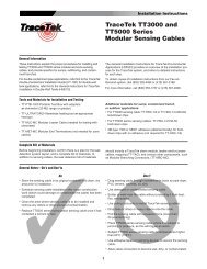
Installation Instructions<strong>TraceTek</strong> <strong>TT1000</strong><strong>Modular</strong> <strong>Sensing</strong> <strong>Cable</strong>General InformationThese instructions explain the proper procedures for installing andtesting <strong>TT1000</strong> modular sensing cables, and provide specifics forsumps, subflooring, and trenches.Use these instructions with the General Installation Instructions for<strong>TraceTek</strong> Leak Detection Systems in Commercial Buildings(H55522). That document provides an overview of the installationprocess for the <strong>TraceTek</strong> system, and refers to detailed instructions(as applicable) for each step.To obtain copies of installation instructions from our Fax-on-Demand system, dial 1-800-329-4494 (415-361-2168 for internationalaccess). A voice prompt will lead you through the process.For more information, call (800) 553-1737 or (415) 361-4900.Tools and Materials for Installation and Testing• TT-PTB-1000 Portable Test Box with adapters orohmmeter (20 MΩ range or greater).• TT-MLC-PC <strong>Modular</strong> Leader <strong>Cable</strong> (needed for testing withohmmeter).• TT-MET-PC <strong>Modular</strong> End Termination.• TT-HDC-1/4 (with adhesive pressure-sensitive backing) orTT-HDC-1/4-200-NA Hold Down-Clips and (obtained locally)3M-type 1300 or 08001 adhesive.Complete Bill of MaterialsBefore beginning installation, confirm there is a plan for the leakdetection system layout, and a complete bill of materials. Inaddition to sensing cables, the leak detection bill of materialsshould include a <strong>TraceTek</strong> alarm module, leader and/or jumpercables, mapping tags (TT-TAG), and various other components,such as modular branching connectors (TT-MBC-PC).General Notes—Do’s and Don’tsDo• Store the sensing cable in its original container in a clean, dryarea prior to installation.• Schedule sensing cable installation after major constructionwork (which could damage or contaminate the cable) has beencompleted.• Clean the area where sensing cable is to be installed andremove any debris or other source of contamination.Don’t• Drag sensing cable through contaminants (such as pipe dope,PVC cement, solvents, oil, or dirt).• Use damaged or contaminated sensing cable.• Solder or weld near the cable without protecting it from heat,flux, and splatter.• Drop tools or sharp or heavy objects onto the cable.• Pull the sensing cable with excessive force (more than50 pounds/20 kg).• Use adhesive tapes or clamping devices to secure the sensingcable.• Allow cable connectors to become wet, dirty, or contaminated.1
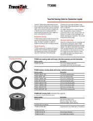
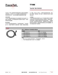
Installation Instructions for <strong>TT1000</strong> <strong>Modular</strong> <strong>Sensing</strong> <strong>Cable</strong>General Layout of <strong>TraceTek</strong> System<strong>Modular</strong> branching connector(TT-MBC-PC)<strong>Modular</strong> jumper cable<strong>Modular</strong> sensing cable(<strong>TT1000</strong>-MSC-xxx-PC)<strong>Modular</strong> leader cable(TT-MLC-PC)<strong>TraceTek</strong> alarmmodule (severalmodels available;TTDM alarm andlocating moduleis shown)<strong>Modular</strong> jumper cable(TT-MJC-xxx-PC)<strong>Modular</strong> end termination(TT-MET-PC)<strong>Modular</strong>sensingcableNote:• Drawing is not to scale.• Not all components may be required.Hold-down clip(TT-HDC-1/4...)<strong>TraceTek</strong> tag(TT-TAG)Installation Steps1. Prepare the area where the sensing cable will be located.• Verify that major construction is complete.• Clean the area where the cable will be installed, to removedebris and sources of contamination.• Install <strong>TraceTek</strong> hold-down clips. For <strong>TraceTek</strong> <strong>TT1000</strong>sensing cables, use 1/4" hold-down clips (TT-HDC-1⁄4...).Clean the floor surface where hold-down clips will be placed,so adhesive can work properly.Position hold-down clips so the sensing cable will provide thedesired leak-detection coverage. To best secure the cable,alternate the direction of the hold-down clips, and install themat intervals of no greater than 6 feet (2 m) and at everychange in direction.Important: Let the adhesive dry per the manufacturer’srecommendation before proceeding with sensing cableinstallation.TT-HDC-1⁄4orTT-HDC-1⁄4-200-NA< 6 ft (2 m)2. Check each length of sensing cable before installation.To ensure that each length of sensing cable is intact and free of contamination,follow the “<strong>Sensing</strong> <strong>Cable</strong> Test Procedure” on page 5.Do not use damaged or contaminated sensing cable.2
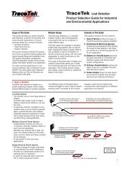
Installation Instructions for <strong>TT1000</strong> <strong>Modular</strong> <strong>Sensing</strong> <strong>Cable</strong>Installation Steps (continued)3. Observe proper precautions when handling sensing cables.Observe the do’s and don’ts printed on page 1 of these instructions;take care to avoid damaging or contaminating sensing cable.4. Connect, orient, install, and test each length of sensing cable in sequence1. Connect a <strong>Modular</strong> End Termination (TT-MET-PC) to the firstsensing cable length to be installed.<strong>Modular</strong> endtermination2. Orient sensing cable so end termination will be away from connectionto the <strong>TraceTek</strong> alarm module. Work outward from thealarm module connection. To help dispense sensing cable onreels (lengths over 10 feet/3 meters), put the reel on an axle.Connector with pinstoward module3. Install sensing cable in accordance with the engineer’s leakdetection layout plan.Pull the cable alongside the installed hold-down clips. Leave6 inches (150 mm) of sensing cable on each end for the connectorservice loop.Important: Verify that the adhesive securing the hold-downclips has dried; liquid adhesive must not contact the cable.Push sensing cable into the hold-down clips and position thesensing cable to lay flat on the surface to be monitored.4. Test each length of sensing cable after installing it andbefore attaching it to cable already installed. Confirm that thesensing cable is clean and intact by following the “<strong>Sensing</strong><strong>Cable</strong> Test Procedure” on page 5.5. Connect the sensing cable to the cable string (lengths ofsensing cables connected in series) previously installed.• Leave a service loop at each connector as shown.• Mark the connector position on the layout plan.• Install <strong>TraceTek</strong> mapping tags (TT-TAG).Note: As an extra precaution on large installations, periodicallytest the entire cable string to confirm that all installedsensing cable is still clean and intact.ServiceLoopR <strong>TraceTek</strong>SystemsUnplug the end termination from the previous length andconnect it to the next length of sensing cable to be installed.Repeat the installation sequence for each length of cable.3
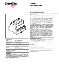
Installation Instructions for <strong>TT1000</strong> <strong>Modular</strong> <strong>Sensing</strong> <strong>Cable</strong>Installation Steps (continued)5. Complete the system.• Install other <strong>TraceTek</strong> components—for example <strong>Modular</strong>Branching Connectors, Weighted Lengths, and <strong>Modular</strong>Jumper <strong>Cable</strong>s—as called for in the system layout. Completethe sensing circuit.Connectorwith pinstoward module<strong>Modular</strong> Branching Connector(shows after middle leg)Middle leg (shows first on map)• Test the sensing circuit (or portions of it) to confirm that thesensing cable is clean and intact. Follow the “<strong>Sensing</strong> <strong>Cable</strong>Test Procedure” on page 5.• Connect the sensing circuit to the <strong>TraceTek</strong> alarm module andactivate the system as soon as is practical. Use the module tomonitor for events during the final stages of construction.6. Take precautions if installation is incomplete at end of work day.At the end of the work day:• Ensure that there are no exposed connectors. Each sensingcable should be connected to a <strong>Modular</strong> Leader <strong>Cable</strong>(TT-MLC-PC), <strong>Modular</strong> End Termination (TT-MET-PC),and/or other sensing cables; check both ends of the cable.• Test and record the condition of installed sensing cable followingthe “<strong>Sensing</strong> <strong>Cable</strong> Test Procedure” on page 5.• If practical, connect the installed sensing cable to the<strong>TraceTek</strong> alarm module. Test the system and put it in operationfollowing the alarm module installation instructions.At the beginning of the next work day:• Check that the installed sensing cable is clean and intact followingthe <strong>Sensing</strong> <strong>Cable</strong> Test Procedure. Compare resultswith those obtained at the end of the previous work day. If necessary,investigate and correct problems before proceeding.<strong>Modular</strong>leader cable<strong>Modular</strong>end termination4
Installation Instructions for <strong>TT1000</strong> <strong>Modular</strong> <strong>Sensing</strong> <strong>Cable</strong><strong>Sensing</strong> <strong>Cable</strong> Test ProcedureMethod with <strong>TraceTek</strong> Portable Test Box (PTB)1. Ensure the end termination is connected to the sensingcable. If checking several lengths of sensing cable in series(a cable string), ensure they are all connected.2. Connect the PTB to the sensing cable(s) as illustrated.3. Verify that the sensing cable is intact; follow the operatinginstructions printed inside the lid of the PTB itself. If the cablestring is intact, the PTB measures the system length (lengthof <strong>TraceTek</strong> sensing cable plus the length equivalents of theweighted lengths and modular branching connectors). If acable or connection is broken, the PTB illuminates its LEDindicating “cable break” and displays a “1” in the leftmostposition of its LCD display.If the cable string is not intact, apply this test procedure tosegments of the system to identify the open connection ordamaged modular length.4. Check the condition of the sensing cable(s), again followingthe PTB operating instructions. If the sensing cables areclean and free of contamination, the current measuredshould be below 10 µA. If the reading exceeds 10 µA, usethe PTB to locate the liquid or contamination and takeappropriate corrective action.Testing a stringof cablesEnd terminationPTBTesting an individuallength of cableEnd terminationEndterminationMethod with Ohmmeter1. Ensure the end termination is connected to the sensingcable. If checking several lengths of sensing cable in series(a cable string), ensure they are all connected.2. Connect a <strong>Modular</strong> Leader <strong>Cable</strong> (TT-MLC-PC) to thesensing cable.3. Verify that the sensing cable is intact• Loop 1: Measure the resistancebetween the yellow and black wiresof the leader cable as illustrated.• Loop 2: Measure the resistancebetween the red and green wires ofthe leader cableTo yellowTo blackTo redTo greenThe readings should roughly equal amultiple of the length of sensing cable:4 times the length of sensing cable (in ft) or12 times the length of sensing cable (in m)Example: 4 x 50 ft of cable = 200 Ω,12 x 15 m of cable = 180 Ω.In addition, the resistance of the two loops should be within 5percent of each other.If the cable string is not intact, apply this test procedure tosegments of the system to identify the open connection ordamaged modular length.4. Check the condition of the sensing cable. Measure the resistancebetween the black and green wires of the leader cable.If the reading is below 20 MΩ, apply this test procedure tosegments of the system to identify the modular sensing cablelength(s) affected, then locate the liquid or contamination andtake appropriate corrective action.Testing a stringof cablesOhmmeterEnd terminationTT-MLC-PCTesting an individuallength of cableEnd terminationEndtermination5
Installation Instructions for <strong>TT1000</strong> <strong>Modular</strong> <strong>Sensing</strong> <strong>Cable</strong>6
Installation Instructions for <strong>TT1000</strong> <strong>Modular</strong> <strong>Sensing</strong> <strong>Cable</strong>7
Installation Instructions for <strong>TT1000</strong> <strong>Modular</strong> <strong>Sensing</strong> <strong>Cable</strong>RBelgiumNV Raychem SADiestsesteenweg 6923010 Kessel-LoTel (32) 16/351-800Fax (32) 16/351-797KoreaRaychem Korea Limited831-45 Yeuksam-DongKangnam-KuSeoul 135Tel (82) 2/557-7752Fax (82) 2/558-5765United KingdomRaychem Ltd.Faraday RoadDorcan, Wiltshire SN3 5HHTel (44) 1793/572-663Fax (44) 1793/572-189United StatesRaychem CorporationCommercial & IndustrialInfrastructure Division300 Constitution DriveMenlo Park, CA 94025-1164Tel (800) 545-6258Fax (800) 611-2323www.raychem.com© 1996 Raychem Corporation Printed in USA H55555 P/N824017 4/96 <strong>TraceTek</strong> is a trademark of Raychem Corporation.