MULLER Eco Terminal Intructions - Bargam UK
MULLER Eco Terminal Intructions - Bargam UK
MULLER Eco Terminal Intructions - Bargam UK
Create successful ePaper yourself
Turn your PDF publications into a flip-book with our unique Google optimized e-Paper software.
30322325-02_E (ME070886) [07/2005]<br />
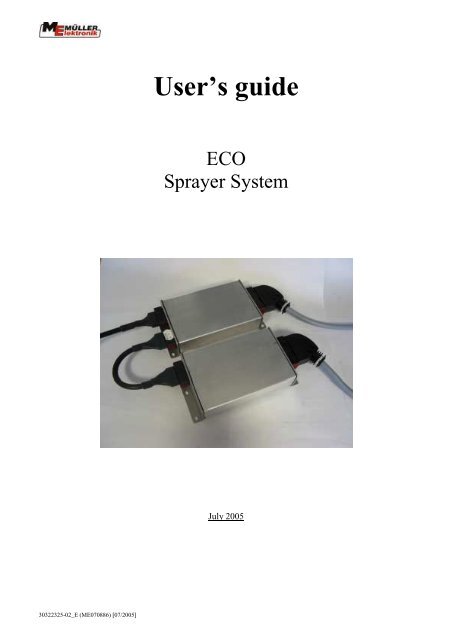
User’s guide<br />
ECO<br />
Sprayer System<br />
July 2005
Contents<br />
1. INTRODUCTION ................................................................ 4<br />
2. SAFETY INSTRUCTIONS .................................................. 5<br />
2.1. Disclaimer:.......................................................................................................5<br />
2.2. Safety measures...............................................................................................5<br />
3. OVERVIEW AND INITIAL OPERATION ............................ 7<br />
4. MASKS............................................................................... 9<br />
4.1. Mask structure ................................................................................................9<br />
4.2. Soft keys in the working mask .....................................................................10<br />
4.3. Machine data masks......................................................................................10<br />
4.3.1. Calibration masks............................................................................................13<br />
4.3.1.1 Flow meter ......................................................................................................14<br />
4.3.1.2 Tank method ...................................................................................................14<br />
4.3.1.3 Nozzle method ................................................................................................16<br />
4.3.1.4 Wheel sensor...................................................................................................17<br />
4.4. Simulated speed.............................................................................................18<br />
4.4.1.1 Boom sections.................................................................................................19<br />
4.5. Working masks..............................................................................................20<br />
4.5.1. Working mask 1..............................................................................................21<br />
4.5.1.1 Spraying data...................................................................................................21<br />
4.5.1.2 Boom sections.................................................................................................22<br />
4.5.2. Working mask 2..............................................................................................24<br />
4.6. Folding masks................................................................................................24<br />
4.7. Tank mask .....................................................................................................26<br />
4.7.1. Manual ............................................................................................................26<br />
4.7.2. TANK-Control................................................................................................27<br />
4.8. Results ............................................................................................................27<br />
5. FUNCTIONS..................................................................... 28<br />
5.1. Foam marking ...............................................................................................28<br />
5.2. Manual pressure adjustment .......................................................................29<br />
6. DISTANCE-CONTROL..................................................... 30<br />
6.1. Setting the working height: ..........................................................................31<br />
6.2. Setting the raised height:..............................................................................31<br />
6.3. Selection of the control type .........................................................................32<br />
6.4. Calibration.....................................................................................................32<br />
6.5. Safety functions:............................................................................................34<br />
Page - 2 - Copyright Müller-Elektronik GmbH u. Co. KG, User‘s Guide ECO Sprayer system (07/05)
7. TRAIL-CONTROL ............................................................ 35<br />
7.1. Initial operation.............................................................................................35<br />
7.1.1. Input of spraying-specific data:.......................................................................37<br />
7.1.2. Calibration:......................................................................................................38<br />
7.2. Operation:......................................................................................................38<br />
7.2.1. Automatic / Manual ........................................................................................38<br />
7.2.2. Middle position ...............................................................................................39<br />
7.2.3. Crab steering ...................................................................................................39<br />
7.2.4. Locking ...........................................................................................................39<br />
8. EXTERNAL EXTENSIONS............................................... 40<br />
8.1. Multifunction grip (MFG)............................................................................40<br />
8.2. S-Box ..............................................................................................................42<br />
8.2.1. Introduction.....................................................................................................42<br />
8.2.2. Assembly and wiring ......................................................................................42<br />
8.2.3. Operating elements .........................................................................................44<br />
9. APPENDIX ....................................................................... 45<br />
9.1. Technical data (Job computer F1)...............................................................45<br />
9.2. Technical data S-Box ....................................................................................45<br />
9.3. Machine data .................................................................................................46<br />
9.4. Glossary..........................................................................................................47<br />
9.5. Abbreviations ................................................................................................48<br />
9.6. List of diagrams.............................................................................................48<br />
9.7. List of tables...................................................................................................49<br />
Copyright Müller-Elektronik GmbH u. Co. KG, User‘s Guide ECO Sprayer System (07/05) Page - 3 -
1. Introduction<br />
With the ECO Sprayer System your machine is equipped with state-of-the-art technology.<br />
Over 10 years experience in the development of CAN-bus components has had considerable<br />
influence here.<br />
This ECO System works with ECO-<strong>Terminal</strong> of Müller-Elektronik GmbH u. Co. KG.<br />
For any questions on the ECO-<strong>Terminal</strong> please refer to the installation and User´s Guide of<br />
the ECO-<strong>Terminal</strong>.<br />
Page - 4 - Copyright Müller-Elektronik GmbH u. Co. KG, User‘s Guide ECO Sprayer system (07/05)
2. Safety instructions<br />
2.1. Disclaimer:<br />
The ECO Sprayer System is specified exclusively for agricultural use. The manufacturer<br />
takes no responsibility for any installation or application outwith this area.<br />
The manufacturer does not accept liability for damage to persons or property resulting from<br />
unspecified use. In such cases all risks are the responsibility of the user.<br />
Specified implementation also includes adhering to the operation and maintenance<br />
requirements stipulated by the manufacturer.<br />
Relevant accident prevention regulations as well as other generally recognised safety,<br />
industrial health and road traffic rules are to be adhered to. In addition the manufacturer<br />
accepts no liability in cases where arbitrary modifications have been made to the device.<br />
2.2. Safety measures<br />
Warning!<br />
!<br />
Always pay attention to this symbol for references to important safety<br />
precautions.<br />
It means attention! Become alert!<br />
It is a question of your safety.<br />
!<br />
Read the user's guide before using the ECO System for the first time.<br />
Copyright Müller-Elektronik GmbH u. Co. KG, User‘s Guide ECO Sprayer System (07/05) Page - 5 -
Observe the following recommended precautions and safety instructions:<br />
! Do not remove any safety mechanisms or labels.<br />
! Before using the device, read and understand this guide. It is of equal importance that<br />
others operating this device also read und understand the manual.<br />
! During maintenance or when using a battery charger, switch off the power supply (pull<br />
out the ISOBUS plug).<br />
! Never service or repair the device while the job computer is switched on.<br />
! When welding on the equipment or on an attached machine, interrupt the power supply<br />
(pull out the ISOBUS plug).<br />
! Use clear water for testing. Only use chemicals once fully acquainted with the<br />
operation of all functions.<br />
! Keep children away from the equipment.<br />
! Do not expose the job computer and the sensors to the direct jet of a high pressure<br />
cleaner.<br />
! Do not open the job computer. Unauthorised opening leads to the loss of any warranty<br />
claims.<br />
! Operate the keys with your finger tips but avoid using fingernails.<br />
! Should any part of this guide remain incomprehensible after reading, contact the dealer<br />
or Mueller-Elektronik Service for further clarification before using the device.<br />
! Read carefully all safety instructions in the manual and the safety labels on the<br />
equipment. Safety labels must always be legible. Replace missing or damaged labels.<br />
Ensure that the current safety labels can be found on all new components. Your<br />
authorised dealer can supply you with spare labels.<br />
! Learn how to operate the machine and controls correctly. Nobody is to operate the<br />
machine without exact instructions.<br />
! Keep the machine and the spare parts in good condition. Unstipulated alterations can<br />
impair the function and/or safety and affect the life span of the machine.<br />
Page - 6 - Copyright Müller-Elektronik GmbH u. Co. KG, User‘s Guide ECO Sprayer system (07/05)
3. Overview and initial operation<br />
The job computer is not sufficient in itself to operate the sprayer. The system can only be<br />
operated once the job computer has been connected via the connector to the basic equipment<br />
of the terminal on the tractor. Is the ECO-<strong>Terminal</strong> connected to the basic equipment, the<br />
system can be switched on and operated by the terminal. Diagram 3-1 illustrates the basic<br />
overview of the equipment on the tractor and the field sprayer.<br />
Diagram 3-1 overview<br />
Copyright Müller-Elektronik GmbH u. Co. KG, User‘s Guide ECO Sprayer System (07/05) Page - 7 -
(1) ECO-<strong>Terminal</strong><br />
(2) Multifunction grip<br />
(3) Tractor basic equipment<br />
(4) Speed sensor<br />
(5) Connection cable machine ECU<br />
(6) Junction cable for second ECU<br />
(7) Master job computer<br />
(8) Slave job computer<br />
(9) Cable loom for Master ECU<br />
(10) Cable loom for Slave ECU<br />
Diagram 3-1 gives an overview of the ECO - <strong>Terminal</strong> with multifunction grip, the basic<br />
equipment for tractors with speed sensor, ECU and cable loom.<br />
The basic equipment supplies the ECO - <strong>Terminal</strong> with voltage, makes the connection to the<br />
machine and gives a connection to a speed sensor.<br />
The multifunction grip is an optional operating unit and is absolutely essential for machines<br />
with complex operation (e.g. field sprayer). It has 8 keys and a switch allowing up to 24<br />
functions to be carried out quickly, exactly and without eye contact. The assignment of the<br />
keys is determined by the job computer and can be referred to page 40. To connect the<br />
multifunction grip, remove the plug from the ECO - <strong>Terminal</strong> basic equipment and connect the<br />
multifunction grip in its place. The basic equipment is then connected to the free 9-pin socket<br />
on the multifunction grip cable.<br />
The connection cable (5), the machine job computer (7) and (8) and the belonging cable<br />
looms (9) and (10) are part of the machine. Here are different configurations possible<br />
depending on the stage of extension. Please take further information from the User´s Guide.<br />
Page - 8 - Copyright Müller-Elektronik GmbH u. Co. KG, User‘s Guide ECO Sprayer system (07/05)
4. Masks<br />
4.1. Mask structure<br />
As soon as the ECU´s have been switched on and selected from the terminal, a working mask<br />
appears on the monitor. From here all of the job computer’s functions can be navigated.<br />
Diagram 4-1 illustrates how the individual masks are connected<br />
Diagram 4-1 Mask structure<br />
As can be seen in Diagram 4-1, the masks counters, tank-filling, boom-folding, DISTANCE-<br />
Control, parameters and manufacturer masks can be called up directly from the working<br />
mask. The soft keys and appear only if these options have been configured.<br />
If the soft key is pressed, the additional mask 1 appears. This has further functions.<br />
To return to the working mask, press again.<br />
If no multifunction grip is connected (emergency operation), further additional masks appear<br />
which have its function. These can be accessed from the working mask by pressing the soft<br />
key several times. The working mask is returned to after the last mask.<br />
Copyright Müller-Elektronik GmbH u. Co. KG, User‘s Guide ECO Sprayer System (07/05) Page - 9 -
4.2. Soft keys in the working mask<br />
Tab. 4-1 Soft keys in the working mask<br />
Soft key Description<br />
Calls up the machine data mask (chap. 4.3 page 10). In the machine<br />
data masks all adjustable values can be seen and altered. From here<br />
further soft keys branch out to the individual calibration masks.<br />
Calls up the folding masks (chap.4.6 page 24). Depending on the<br />
function range of the boom the soft keys for folding are available here<br />
in either one or two masks.<br />
Calls up the DISTANCE-Control mask (chap.6 page 30).<br />
4.3. Machine data masks<br />
Switches the TRAIL-Control on and off (see chap. 7 page 35). This is<br />
not displayed when the machine is also equipped with DISTANCE-<br />
Control. In this case this function is only to be found on the multifunction<br />
grip.<br />
Switches on to the additional mask 1 (see Diagram 4-1 page 9) which<br />
has further soft keys for other functions.<br />
Calls up the counters mask (chap. 4.7.2 page 27). In the counters mask<br />
the daily and total counters are displayed.<br />
Calls up the tank-filling mask (chap.4.7 page 26).This mask combines<br />
all tank-relevant functions.<br />
Switches from manual/automatic for the spraying function<br />
Middle position: This soft key belongs to the range of “TRAIL Control”<br />
functions. As long as the key is pressed, the steerage is in a middle<br />
position (chap.7.2.2 page 39).<br />
Switches the working mask mode<br />
(see chap.4.5 page 20).<br />
Tab. 4-2 Soft keys in the machine data mask<br />
Soft key Description<br />
Stores the pump rpm as set value<br />
Calls up the mask for flow meter calibration<br />
(see chap.4.3.1.1 page 14).<br />
Proceeds to the next machine data mask<br />
Returns to working mask<br />
Calls up the wheel sensor calibration mask<br />
(see chap.4.3.1.4 page 17)<br />
Calls up the boom section mask (see chap. 4.4.1.1 page 19).<br />
Page - 10 - Copyright Müller-Elektronik GmbH u. Co. KG, User‘s Guide ECO Sprayer system (07/05)
Soft key Description<br />
Calls up the masks DISTANCE-Control (see chap 6 page 30).<br />
Calls up the TRAIL-Control calibration mask (see chap. 7 page 35).<br />
Calls up Configuration mask<br />
Diagram 4-2 Machine data page 1 Diagram 4-3 Machine data page 2 Diagram 4-4 Machine data page 3<br />
Tab. 4-3 Machine data page 1<br />
Parameter Description<br />
Set value The pre-set value is sprayed, when the sprayer is working in<br />
automatic mode.<br />
Working width Set the working width on the field sprayer.<br />
! This value must be set exactly, as it affects the area<br />
measurement and the amount sprayed.<br />
Imp. wheel sensor If a speed sensor is connected (attached sprayer) the pulses / 100 m<br />
are set here. If the value is not known a calibration can be carried<br />
out (see chap.4.3.1.4 page 17).<br />
! This value must be set exactly, as it affects the area<br />
measurement and the amount sprayed.<br />
Control constant The regulating factor adapts to the speed of monitoring. Should,<br />
during travel at a constant speed, the spray rate jump around the<br />
pre-set value, the factor must be reduced. If the spray rate does not<br />
adapt quickly enough to a change in speed, the factor must be<br />
increased<br />
Max. pressure If a pressure sensor is installed, the maximum pressure is entered<br />
here. An alarm is set off if the pressure exceeds this value.<br />
Min. pressure If a pressure sensor is installed, the minimum pressure is entered<br />
here. An alarm is set off if the pressure falls below this value.<br />
Min. operating speed Set the minimum operating speed here. The boom section main<br />
switch on the field sprayer switches off automatically if the speed<br />
falls below this value. When this happens the icon appears on<br />
the working mask.<br />
Min. auto speed “Min auto speed” determines the minimum speed for automatic<br />
fluid regulation. Regulation switches on to manual operation if the<br />
speed falls below this value. This function does not apply when the<br />
value is 0.<br />
Copyright Müller-Elektronik GmbH u. Co. KG, User‘s Guide ECO Sprayer System (07/05) Page - 11 -
Parameter Description<br />
This parameter is used typically in combination with “Min.<br />
operating speed” e.g. Min. operating speed=2 km/h” and “Min auto<br />
speed = 4 km/h”. When the sprayer is switched on when not in<br />
motion, the job computer switches the icon on to the display<br />
in order to show that spraying is not possible. Depending on the<br />
configuration of the nozzle type, the main valve remains closed<br />
and/or the by-pass open and/or the boom section valves closed.<br />
With a speed between 2 and 4 km/h the boom sections valves are<br />
closed, whilst regulation remains in manual operation and the icon<br />
is displayed.<br />
Both parameters can be set separately. However it must be<br />
guaranteed that “Min. operating speed” >= “Min. auto speed”,<br />
otherwise only “Min. operating speed” will be evaluated.<br />
Max. wind speed If a wind sensor is installed the maximum wind speed is entered<br />
here. An alarm is set off if the wind speed exceeds this value.<br />
Tab. 4-4 Machine data page 2<br />
Parameter Description<br />
Tank size Size of the tank for the spraying fluid.<br />
Tank level alarm An alarm is set off if the amount in the tank falls below this<br />
value.<br />
Pulses main flow meter The number of pulses per litre for the main flow meter can be set<br />
here. If the value is not known, a calibration can take place (see<br />
chap.4.3.1.1 page 14).<br />
! This value must be set exactly as it has a direct influence on<br />
the spray rate.<br />
Pump rpm If a sensor for the measurement of the pump rpm is installed, the<br />
standard rpm is entered here. A warning is displayed if the value<br />
varies by a certain percentage (manufacturer-specific).<br />
Tab. 4-5 Machine data page 3<br />
Parameter Description<br />
Section switching It can be differentiated between “sequential operation” and “nest<br />
treatment”. The functions are described in chap.4.5.1.2 page 22.<br />
! After changing the setting, the job computer must be switched off<br />
and on again. Only then is the change effective.<br />
Filling mode Depending on the configuration, the following points can be selected:<br />
“manual”, “TANK-Control”. Chap.4.7 page 26 describes the functions<br />
and handling.<br />
! After changing the setting, the job computer must be switched off<br />
and on again. Only then the change is effective.<br />
Page - 12 - Copyright Müller-Elektronik GmbH u. Co. KG, User‘s Guide ECO Sprayer system (07/05)
Parameter Description<br />
Joystick type Change-over of the functionality of the MFG<br />
„without Joystick“ = For all functions the softkeys are indicated. The<br />
MFG can be used.<br />
„ME-MFG“ = The softkeys of all functions on the MFG are removed<br />
out of the masks. These functions can only be operated by the MFG.<br />
The number of masks is reduced because of this and the whole<br />
operation is more clearly.<br />
„disclaim ME-MFG“ = All pressings of the keys on the MFG are<br />
disclaimed by the ECO sprayer. The MFG has no effect on the<br />
sprayer.<br />
! After changing the setting, the job computer must be switched off<br />
and on again. Only then the change is effective.<br />
Circulation type Here the circulation type is defined. It is differentiated between the<br />
following types:<br />
„without constant pressure“: For armatures without constant<br />
pressure function<br />
Software version<br />
number<br />
4.3.1. Calibration masks<br />
„constant pressure“: for armatures with constant pressure function<br />
„D-Type“: by using a constant pressure membrane.<br />
! After changing the setting, the job computer must be switched off<br />
and on again. Only then the change is effective.<br />
At the bottom of the machine data page 3 you find the software<br />
version numbers.<br />
SPRECO1 is the version number of the Master-ECU which is<br />
responsible for Spraying functions and Distance Control.<br />
SPRECO2 is the number for the slave-ECU, responsible for TRAIL-<br />
Control and hydraulics.<br />
OP: gives the version of the object pool.<br />
Calibration of individual components serves the purpose of balancing out manufacturing<br />
variations and changes which have occurred in the course of time due to wear and tear etc.<br />
The individual calibration steps must be carried out as accurately as possible. Only then can<br />
the best possible results be achieved. It is recommended that all functions be examined for<br />
accuracy and if necessary calibrated again at the beginning of each season. A new calibration<br />
should be carried out immediately if inaccuracies occur during the season.<br />
The following chapter describes the procedure for the various calibrations.<br />
Copyright Müller-Elektronik GmbH u. Co. KG, User‘s Guide ECO Sprayer System (07/05) Page - 13 -
4.3.1.1 Flow meter<br />
Before initial operation, the machine’s flow meter must be calibrated. The number of pulses<br />
per litre can change during the life span of a flow meter. A repeat calibration at least once<br />
before the beginning of the spraying season is recommended.<br />
! Important! Only clear water is to be used for this purpose.<br />
Tab. 4-6 Soft keys flow meter calibration<br />
Soft key Description<br />
Starts the main flow meter calibration using the tank method<br />
(see 4.3.1.2 page 14)<br />
4.3.1.2 Tank method<br />
Starts the main flow meter calibration using the nozzle method<br />
(see 4.3.1.3 page 16)<br />
Returns to the machine data mask<br />
1. Fill the tank with clear water.<br />
2. Determine the total weight of the tractor and the field sprayer.<br />
3. Switch on all boom sections.<br />
4. Set manual control.<br />
5. Start calibration process with the soft key. The mask as illustrated in Diagram 4-6.<br />
Diagram 4-5 Calibration tank method<br />
6. Switch on spaying with the key on the MFG and spray a few hundred litres. During<br />
this time the number of litres increases on the display.<br />
7. Switch off the field sprayer by pressing the key once more. Counting is<br />
discontinued.<br />
8. Stop the calibration process by pressing .<br />
Page - 14 - Copyright Müller-Elektronik GmbH u. Co. KG, User‘s Guide ECO Sprayer system (07/05)
9. Determine the amount sprayed and enter (see Diagram 4-6 Calibration tank method<br />
input).<br />
Diagram 4-6 Calibration tank method input<br />
10. The new value (pulses per litre) is calculated and displayed in the machine data mask.<br />
The calibration process can be interrupted at any time using the soft key .<br />
Copyright Müller-Elektronik GmbH u. Co. KG, User‘s Guide ECO Sprayer System (07/05) Page - 15 -
4.3.1.3 Nozzle method<br />
Using the nozzle method the value pulses/litre is measured with the nozzle flow meter. An<br />
approximate pulse number (pulses/l) must be entered, before a calibration on the flow meter<br />
with the nozzle method is possible.<br />
Attention! The tank method is more time-consuming, but more accurate<br />
than the nozzle method.<br />
!<br />
Do not change the current flow during the calibration!<br />
To ensure accurate calibration, the working width (Tab. 4-3 page 11) and the nozzles per<br />
boom section (chap.4.4 page 18) must be checked before the calibration process begins.<br />
Procedure:<br />
1. Fill the tank with clear water.<br />
2. Switch on all sections.<br />
3. Set manual control.<br />
4. Start calibration process by pressing .<br />
Diagram 4-7 Nozzle method<br />
5. Switch on spraying with the key on the MFG.<br />
6. Use a measuring jug to determine the current nozzle flow per minute. It is advisable to<br />
establish the average flow from several nozzles.<br />
7. The current measured value is displayed in the calibration mask after “measured flow”.<br />
(see Diagram 4-7).<br />
8. Stop the calibration process by pressing .<br />
9. Switch off the MFG by pressing the key.<br />
10. Enter the determined value per nozzle in l/min (see Diagram 4-8).<br />
Page - 16 - Copyright Müller-Elektronik GmbH u. Co. KG, User‘s Guide ECO Sprayer system (07/05)
4.3.1.4 Wheel sensor<br />
Diagram 4-8 Nozzle method input<br />
The calibration mask can be selected in the machine data mask. Some preparation is<br />
necessary before the calibration process can begin.<br />
!<br />
Attention! The calibration must be carried out accurately. The speed, the<br />
area measurement and the amount sprayed are all affected by it.<br />
1. Measure and mark a distance of 100 m on the field (tank half full).<br />
2. Drive the tractor to the marked line.<br />
3. To start the calibration process, press the<br />
keys appear.<br />
key. The key disappears. The and<br />
4. Drive a hundred meters and stop. During the journey the current pulses measured are<br />
displayed.<br />
5. To confirm the pulses measured, press the key at the end. The new value is now<br />
displayed in the machine data mask. The calibration process can be interrupted by<br />
pressing the key instead of . The old values remain unchanged.<br />
Diagram 4-9 Calibration of wheel sensor<br />
Copyright Müller-Elektronik GmbH u. Co. KG, User‘s Guide ECO Sprayer System (07/05) Page - 17 -
4.4. Simulated speed<br />
Press the soft key to start simulation. An input field is displayed. Enter the speed to be<br />
simulated here.<br />
Diagram 4-10 Speed simulation<br />
The value is pre-set to 0 km/h. The user can enter any value up to 25.5 km/h. Simulation can<br />
be ended again by pressing the soft key once more. When the job computer is restarted<br />
simulation is always deactivated. The last value to be set can however be called up again by<br />
pressing .<br />
!<br />
Important:<br />
For reasons of safety the TRAIL-Control function cannot operate with<br />
simulated speed. TRAIL-Control remains in manual operation mode.<br />
Page - 18 - Copyright Müller-Elektronik GmbH u. Co. KG, User‘s Guide ECO Sprayer system (07/05)<br />
Input field for the speed to be<br />
simulated
4.4.1.1 Boom sections<br />
Diagram 4-11 Section settings<br />
The number of boom sections and number of nozzles per boom section can be changed in this<br />
mask by selecting the corresponding input field and entering the value.<br />
In addition it is possible to switch the boom sections on and off permanently.<br />
Select the required boom sections with and . The boom sections selected can be<br />
recognised by the highlighted nozzle symbol. By pressing the key, the symbol alternates<br />
between the nozzle and the scored out nozzle .<br />
The boom section is permanently switched off when the symbol appears behind a boom<br />
section. In this case switching on in the field sprayer working mask is not possible in normal<br />
section switching mode.<br />
Copyright Müller-Elektronik GmbH u. Co. KG, User‘s Guide ECO Sprayer System (07/05) Page - 19 -
4.5. Working masks<br />
2 different working masks can be displayed in which all values and conditions required<br />
during operation are displayed.<br />
Diagram 4-12 Working mask 1<br />
Diagram 4-13 Working mask 2<br />
Diagram 4-12 and Diagram 4-13 illustrate the 2 working masks. These can be switched using<br />
the soft keys and .<br />
Comparing the 2 masks shows that only specific areas change. We differentiate here between<br />
permanent and selective display areas.<br />
Page - 20 - Copyright Müller-Elektronik GmbH u. Co. KG, User‘s Guide ECO Sprayer system (07/05)
In the permanent areas the spraying data and<br />
status of the boom sections are displayed.<br />
Switching does not affect these. In the<br />
selective areas the display changes. Symbols<br />
which indicate the current status of<br />
aggregates, controllers etc. are displayed in<br />
the working mask 1. Working mask 2<br />
displays information concerning tank level,<br />
rpm etc.<br />
4.5.1. Working mask 1<br />
permanent<br />
selective<br />
permanent<br />
selective<br />
selective<br />
Diagram 4-14 Basic structure of the working mask<br />
The symbols displayed in this mask are described together with the corresponding functions.<br />
For this reason the permanent areas only are explained here.<br />
4.5.1.1 Spraying data<br />
Spray rates<br />
Current value Pre–set value<br />
Diagram 4-15 Spraying data in the working<br />
mask<br />
proportional adjustment of pre set value<br />
Diagram 4-16 Adjusted pre-set rate<br />
Pre-set value: Spray rate in l/ha entered by<br />
operator.<br />
Current value: Current spray rate in l/ha.<br />
Speed: Sprayer’s current speed in km/h. If there<br />
is no speed determination on the sprayer, the<br />
speed of the tractor has to be used.<br />
Spray pressure: Current pressure of the<br />
spraying fluid in bar.<br />
In automatic mode the pre-set rate can be<br />
adjusted in steps of 10%. After adjustment the<br />
percentage is displayed for about 2 seconds.<br />
Copyright Müller-Elektronik GmbH u. Co. KG, User‘s Guide ECO Sprayer System (07/05) Page - 21 -
manual mode<br />
Diagram 4-17 Manual spraying mode<br />
Diagram 4-18 Minimum working speed<br />
Diagram 4-19 Minimum auto speed<br />
4.5.1.2 Boom sections<br />
The symbol appears in the display, when the<br />
sprayer is switched to manual mode. Using the<br />
MFG , keys (see chap. 8.1 page 40)<br />
the spray pressure can be manually adjusted.<br />
If the symbol appears in the display, this<br />
means that a pre-set rate of 0 l/ha has been set or<br />
that the working speed has fallen below the<br />
minimum (see Tab. 4-3 Page 11). Even if the<br />
main sprayer switch is on, the sprayer can only<br />
be switched on when all conditions have been<br />
fulfilled again.<br />
If the symbol appears in the display, this<br />
means that the current speed is lower than “Min.<br />
auto speed” and higher than “Min. operating<br />
speed.” (see Tab. 4-3 page 11)<br />
The boom sections are illustrated by bars and triangular symbols underneath the boom. The<br />
bars correspond to pre-selected boom sections. The triangles symbolise spraying cones<br />
representing switched-on boom sections.<br />
Diagram 4-20 Boom sections; main switch off; all sections are pre-selected<br />
Diagram 4-21 Boom sections; main switch on; sections 3, 4 and 5 are in spraying mode<br />
There are 2 variations for the switching of boom sections. Differentiation is between<br />
“sequential operation” and “nest treatment”. Switching between these 2 modes of operation is<br />
described in Tab. 4-5 page 12.<br />
4.5.1.2.1 Sequential operation<br />
The working mode “sequential operation” is conceived for normal spraying operations. It is<br />
also suitable for spraying wedge-shaped areas and strips which are narrower than the working<br />
width of the sprayer.<br />
Individual boom sections can be switched using the 4 MFG keys (see chap. 8.1 page 40).<br />
Individual boom sections can also be switched permanently in the boom section mask<br />
(chap.4.4.1.1 page 19).<br />
Page - 22 - Copyright Müller-Elektronik GmbH u. Co. KG, User‘s Guide ECO Sprayer system (07/05)
Tab. 4-7 Boom section soft keys<br />
Symbol Description<br />
If a boom section is already switched on, further boom sections from<br />
right to left will be switched on when the key is pressed. If no<br />
boom sections are switched on (active), then only the boom section on<br />
the outside left will be switched on when the key is pressed. By<br />
pressing the key, all active boom sections from left to right are<br />
switched off.<br />
If a boom section is already switched on, further boom sections from<br />
left to right will be switched on when the key is pressed. If no<br />
boom sections are switched on (active), then only the boom section on<br />
the outside right will be switched on when the key is pressed. By<br />
pressing the key, all active boom sections from right to left are<br />
switched off.<br />
If the last boom section is switched off using the boom section key while the main boom<br />
section switch is on, then this will be automatically switched off. A pre-selection can now be<br />
carried out using the boom section keys. Switching on must be done at the main switch. If no<br />
boom sections have been pre-selected, all boom sections are switched on by the main switch.<br />
4.5.1.2.2 Nest treatment<br />
The working mode nest treatment is conceived for the specific treatment of small patches of<br />
weeds. It is possible to switch on and off one or more boom sections in the middle of an area<br />
being processed.<br />
Operation is also carried out using the 4 MFG keys<br />
40).<br />
(see chap. 8.1 page<br />
In this working mode a cursor is displayed between the linkage and the boom sections. The<br />
cursor can be moved from left to right using the keys. The keys are used<br />
for switching the boom sections. Both have the same function.<br />
Independent of the position of the main switch, the cursor can be moved on any boom section<br />
and the status of the boom section adjusted.<br />
Diagram 4-22 Nest treatment, main switch off<br />
Diagram 4-23 Nest treatment, Main switch on<br />
Boom section 4 is pre-selected. Boom section 2 can<br />
be pre-selected using the keys or<br />
Boom sections 3 and 4 switched on, boom section 1<br />
can be switched on using the keys or<br />
Characteristics:<br />
When the main switch is switched off, all switched on boom sections are also switched off. If<br />
no boom sections have been pre-selected, all boom sections are switched on by the main<br />
switch.<br />
Copyright Müller-Elektronik GmbH u. Co. KG, User‘s Guide ECO Sprayer System (07/05) Page - 23 -
Diagram 4-22 illustrates the allocation of the symbols for the nest treatment on the MFG,<br />
displayed on the additional mask 2.<br />
Diagram 4-24 MFG allocation for nest treatment<br />
4.5.2. Working mask 2<br />
The symbols displayed in this mask are described together with the corresponding functions.<br />
For this reason the selective areas only are explained here, as only these are affected when<br />
the working mask 2 is switched to.<br />
Diagram 4-25 Working mask info<br />
Diagram 4-26 Working mask info<br />
4.6. Folding masks<br />
Current tank content: Depending on how the<br />
sprayer is equipped, the theoretical or measured<br />
tank contents are displayed here.<br />
Flow rate per minute: Flow rate through the<br />
main flow meter<br />
Area performance<br />
Area to be operated: With the current tank<br />
content and the momentary spray rate the area<br />
displayed here can still be operated.<br />
Distance to be operated: Under present<br />
conditions this distance can still be covered<br />
Wind speed: *1) Current wind speed measured<br />
Fan rpm: *1) Current fan rpm measured<br />
Pump rpm: *1) Curent pump rpm mesured<br />
*1) These values are only displayed when the<br />
corresponding sensors have been installed.<br />
All keys needed for folding the boom can be found in the folding masks. Depending on the<br />
type of boom, a varying number of keys are available. This means that you will not find all<br />
keys described here on the terminal. Not all variations are described here.<br />
Page - 24 - Copyright Müller-Elektronik GmbH u. Co. KG, User‘s Guide ECO Sprayer system (07/05)
Tab. 4-8 Soft keys Folding masks<br />
Soft key Description<br />
Unfolds right and left simultaneously<br />
Folds in right and left simultaneously<br />
Unfolds left<br />
Unfolds right<br />
Folds in left<br />
Folds in right<br />
Folds in inside left<br />
Unfolds inside left<br />
Folds in inside right<br />
Unfolds inside right<br />
Diagram 4-27 Example 1 Folding mask<br />
Folds in outside left and right simultaneously<br />
Unfolds outside left and right simultaneously<br />
Diagram 4-28 Example 2 Folding mask<br />
Copyright Müller-Elektronik GmbH u. Co. KG, User‘s Guide ECO Sprayer System (07/05) Page - 25 -
With all versions of folding masks additional keys for linkage correction are displayed as<br />
long as there is room for these keys:<br />
- If there is only one row of soft keys (soft keys facing each other), the soft keys for<br />
raising and lowering the bars are displayed.<br />
- If there is a further row not in use, these soft keys will be included for sloping<br />
correction: and .<br />
4.7. Tank mask<br />
4.7.1. Manual<br />
Tab. 4-9 Soft keys manual filling<br />
Soft key Description<br />
Tank full; the tank content is set to the value of the tank size (see<br />
Diagram 4-3 page 11)<br />
Tank empty; the tank content is set to 0.<br />
Return to working mask<br />
The manual filling mode allows only the tank content to be set at “full” or “empty” or the<br />
manual input of a value.<br />
Page - 26 - Copyright Müller-Elektronik GmbH u. Co. KG, User‘s Guide ECO Sprayer system (07/05)
4.7.2. TANK-Control<br />
TANK-Control is a measurement system, which continually measures and displays the<br />
current tank content.<br />
Tab. 4-10 Soft keys TANK-Control<br />
Soft key Description<br />
Sets filling to the maximum value (value of the tank size see Diagram<br />
4-3 page 11).<br />
Returns to working mask.<br />
Diagram 4-29 Filling mask TANK-Control<br />
4.8. Results<br />
This mask displays all counters. There are two kinds of counters – daily counters and total<br />
counters. The daily counters can be reset by the operator at any time. The total counters<br />
cannot be reset.<br />
Tab. 4-11 Soft keys for the results mask<br />
Soft key Description<br />
Deletes volume<br />
Deletes area<br />
Deletes distance<br />
Deletes work time<br />
Returns to working mask<br />
Deletes all counters<br />
Copyright Müller-Elektronik GmbH u. Co. KG, User‘s Guide ECO Sprayer System (07/05) Page - 27 -
Diagram 4-30 Counters mask<br />
5. Functions<br />
5.1. Foam marking<br />
Variation 1:<br />
When the sprayer is equipped with a foam marker the corresponding soft keys can be found<br />
in the additional mask 1.<br />
Tab. 5-1 Soft keys for the foam marker<br />
Soft key Description<br />
Switches the foam marker on the left on/off<br />
Switches the foam marker on the right on/off<br />
The active foam marker is displayed on the side in question beside the boom ( )<br />
There are two variations for switching foam marking.<br />
With this variation there are only the keys. The foam marker required can be<br />
switched on and off using the corresponding key.<br />
Page - 28 - Copyright Müller-Elektronik GmbH u. Co. KG, User‘s Guide ECO Sprayer system (07/05)
Variation 2:<br />
Tab. 5-2 Soft keys for foam marking<br />
Soft key Description<br />
Change to the foam marker on the left<br />
Change to the foam marker on the right<br />
Switch off foam marker<br />
The active foam marker is displayed on the side in question beside the boom ( )<br />
The keys and are displayed. When foam marking is switched off, the or<br />
keys are used to switch on the corresponding foam marker. Switching to the other side<br />
takes place using the key for the opposite side etc. Only a change from right to left can take<br />
place. Foam marking is switched off by pressing the key.<br />
5.2. Manual pressure adjustment<br />
The spraying mode automatic/manual can be switched using the key. In manual mode,<br />
the symbol is displayed beside the current spray rate. The spraying pressure can be<br />
adjusted using the and keys on the terminal or the keys and on the MFG<br />
(see chapter 4.5.1.1 page 21).<br />
Copyright Müller-Elektronik GmbH u. Co. KG, User‘s Guide ECO Sprayer System (07/05) Page - 29 -
6. DISTANCE-Control<br />
DISTANCE-Control automatically maintains the pre-set distance from the boom to the target<br />
surface. Two ultrasonic sensors installed near the ends of the boom constantly measure the<br />
current distance to the ground or plant surface. Further sensors provide information about<br />
deflection and inclination of the boom frame. By means of these values the job computer<br />
determines the current status and the necessary reaction to height and inclination deviations.<br />
The current status of the DISTANCE-Control (manual / automatic) is shown in the working<br />
mask on the boom. In manual mode the symbol appears on the boom and disappears in<br />
automatic mode. The key on the MFG, or with emergency operation the soft key in<br />
the additional mask 1 is used for switching.<br />
Tab. 6-1 Soft keys DISTANCE-Control calibration<br />
Soft key Description<br />
Sets the working height when DISTANCE-Control is in manual mode.<br />
Sets the excavation height when DISTANCE-Control is in manual<br />
mode.<br />
Increases the working or raised height when DISTANCE-Control is in<br />
automatic mode.<br />
Reduces the working or raised height when DISTANCE-Control is in<br />
automatic mode<br />
Sets the control type<br />
Starts the 1 st calibration process<br />
Starts the 2 nd calibration process<br />
Starts the 3 rd calibration process<br />
Returns to the working mask<br />
Page - 30 - Copyright Müller-Elektronik GmbH u. Co. KG, User‘s Guide ECO Sprayer system (07/05)
Diagram 6-1 DISTANCE-Control mask<br />
Some information has to be entered before DISTANCE-Control can be used. Subsequently a<br />
calibration has to be carried out.<br />
6.1. Setting the working height:<br />
The working height is determined by DISTANCE-Control when the boom section main<br />
switch is on. In order to program this height the following steps have to be carried out:<br />
1. Switch DISTANCE-Control to manual mode using the key on the MFG.<br />
2. Set the boom to the required working height.<br />
3. Press to store this information.<br />
The working height is now stored and will be set automatically by DISTANCE-Control when<br />
it is in automatic mode and the boom section main switch is on.<br />
The working height can also be set during operation. For this purpose the boom section<br />
switch must be on and the following steps carried out:<br />
1. Call up DISTANCE-Control mask using the soft key in the working mask.<br />
2. With the soft keys and set to the required height. Ready!<br />
6.2. Setting the raised height:<br />
The raised height is determined by DISTANCE-Control when the boom section main switch<br />
is off. In order to program this height the following steps have to be carried out:<br />
1. Switch the DISTANCE-Control to manual mode using the key<br />
on the MFG.<br />
2. Set the boom to the required working height.<br />
3. Press to store this information.<br />
The raised height is now stored and will be set automatically by DISTANCE-Control when it<br />
is in automatic mode and the boom section main switch is off.<br />
Copyright Müller-Elektronik GmbH u. Co. KG, User‘s Guide ECO Sprayer System (07/05) Page - 31 -
If DISTANCE-Control is in automatic mode (boom section main switch off) the raised height<br />
can be set as follows:<br />
1. Call up DISTANCE-Control mask using the soft key in the working mask.<br />
2. With the soft keys and set to the required height. Ready!<br />
6.3. Selection of the control type<br />
DISTANCE-Control operates normally with a combination of height and inclination control.<br />
The type of control in the DISTANCE-Control mask can be changed using the soft key<br />
. Differentiation is made between height control ( ), inclination control ( ) and a<br />
combination of both. Specific applications can be selected by repeatedly pressing the<br />
key in the corresponding mode.<br />
6.4. Calibration<br />
Specific data for each boom type is determined once. These are stored as master data in the<br />
job computer and cannot be altered by the user. The user however is responsible for<br />
optimisation by carrying out calibration. All parameters which can vary due to production or<br />
can change during the life span of the machine are recorded here.<br />
!<br />
Important:<br />
1. The calibration must be carried out for each sprayer with DISTANCE-Control!<br />
2. Calibration should be repeated at least once a year at the beginning of the season.<br />
3. The sprayer must be positioned horizontally on ground which is even and has no<br />
slope. There should be no hollows under the ultrasonic sensors. The ground surface<br />
should not be too smooth (e.g. asphalt or concrete) otherwise the ultrasonic signals<br />
can get lost.<br />
4. All mobile parts of the boom suspension must be free of paint and sufficiently<br />
lubricated.<br />
5. The correct working width must be entered in the machine data.<br />
Correct functioning of DISTANCE-Control after the calibration process is only possible if all<br />
these points are adhered to. Regular maintenance of all mobile parts is absolutely essential to<br />
ensure long-lasting and correct functioning. Changes to the manoeuvrability of the boom<br />
suspension can cause grave impairment to control performance, which even a repeat<br />
calibration may not be able to rectify.<br />
The calibration process is carried out in three consecutive stages. The individual stages are<br />
clearly separated but should be carried out successively during one process. The machine<br />
must be stationary during this process. If problems or operating errors occur, calibration will<br />
be automatically terminated and the original parameters restored. The process can be<br />
interrupted manually at any time by pressing the soft key.<br />
During calibration:<br />
The functions of the multifunction grip remain active; boom adjustment to the defaults can<br />
therefore be carried out either via the multifunction grip.<br />
Page - 32 - Copyright Müller-Elektronik GmbH u. Co. KG, User‘s Guide ECO Sprayer system (07/05)
Procedure:<br />
1. Press the soft key. The calibration process begins and the following text appears:<br />
Horizontal calibration<br />
Place boom in a horizontal position at a height of 2m<br />
And press:<br />
2. Now place the boom in a horizontal position at a height of 2m. In this position the boom<br />
must be able to tilt freely to the ground. If this is not the case select a lower height. To<br />
help with setting, the height of the boom on the left and right are displayed in the menu<br />
Depending on the position the following text appears:<br />
Boom is now horizontal<br />
or<br />
Boom is not horizontal<br />
3. When the boom is horizontal the setting is stored using the key. Now and again wind<br />
can cause the boom to move 2-3 cm back and forth so that the display “Boom is now<br />
horizontal” wavers on the monitor. In this case press the key several times until the<br />
input is accepted.<br />
4. As soon as the first setting is completed the soft key disappears and this key appears<br />
.<br />
5. To start the second calibration step press the Soft key . This text appears :<br />
Manual Calibration<br />
Tilt the boom to the left for 5 seconds<br />
Copyright Müller-Elektronik GmbH u. Co. KG, User‘s Guide ECO Sprayer System (07/05) Page - 33 -
6. Now press down the left side by hand ( ! Attention! not via the slope adjustment)<br />
until the ultrasonic sensor is about 40 cm above the ground. As soon as the deflection is<br />
sufficient the following text appears:<br />
7. Hold the boom in the deflected position for about 5 seconds and then let go. The boom<br />
should now move itself back into the horizontal position. If the display does not switch to<br />
“Move back the boom to the horizontal position“ press down the boom once more, this<br />
time further than the first time.<br />
! The ground must not be touched.<br />
8. Once the boom is horizontal this step can be concluded by pressing . The key<br />
disappears and the key appears.<br />
9. Press to start step 3. The following text appears:<br />
10. Now an automatic process is started. The boom will be raised first on the left and then on<br />
the right and subsequently returned to the horizontal position, during which it must not<br />
touch the ground. If, after this, the horizontal position is not set correctly this does not<br />
mean that the calibration has failed.<br />
11. Observe the movement of the boom. If something is not correct, the process can be<br />
terminated by pressing key. All three steps must then be carried out once again.<br />
12. If this step has also been concluded successfully, the following text appears:<br />
If the new calibration values are to taken over the key has to be pressed once more.<br />
With the key the new calibration values can be rejected.<br />
Once the calibration has been fully completed, DISTANCE-Control is ready for use and can<br />
be switched to automatic mode by pressing the key in the additional mask 1.<br />
6.5. Safety functions:<br />
Move back the boom to the horizontal position<br />
and<br />
Boom is now horizontal<br />
or<br />
Boom is not horizontal<br />
Automatic calibration: please wait...<br />
Calibration completed. Please press ok.<br />
Under specific safety-relevant conditions DISTANCE-Control is switched to manual mode.<br />
- Maximum speed of 15 km/h is exceeded<br />
- Error messages involving DISTANCE-Control<br />
- Activation of another function involving DISTANCE-Control (folding etc.)<br />
- Signal from other sensors e.g. locking, lift mast sensor etc.<br />
- Start of calibration<br />
- Short term loss of sensors<br />
Page - 34 - Copyright Müller-Elektronik GmbH u. Co. KG, User‘s Guide ECO Sprayer system (07/05)
7. TRAIL-Control<br />
The function TRAIL- Control ensures that an attached field sprayer automatically stays in the<br />
trail of the tractor The current position of the complete system is recorded via a sensor<br />
(Gyroscope) on the tractor and a sensor (Potentiometer) at the pivot of the machine's steering.<br />
The job computer uses this data to calculate the required reaction to the hydraulics so that the<br />
sprayer can follow in the trail of the tractor. An inclination sensor (optional) provides<br />
information on the slope of the ground. With this information automatic slope regulation can<br />
be carried out.<br />
Operation of the TRAIL -Control function is integrated in the job computer.<br />
The following chapter describes the controls, their operation and calibration.<br />
7.1. Initial operation<br />
Before TRAIL Control can be used, the sensor (Gyroscope; Diagram 7-1) must be mounted<br />
to the tractor.<br />
Diagram 7-1 Gyroscope<br />
Diagram 7-2 Gyroscope bracket Diagram 7-3<br />
Gyroscope with<br />
bracket<br />
Diagram 7-2 illustrates the mounting bracket for the gyroscope. This must be mounted<br />
perpendicularly and vibration-free on to the rear of the tractor. The gyroscope is then<br />
placed in the bracket and secured with a wing screw (see Diagram 7-3)<br />
! The label “TOP-OBEN” must point upwards.<br />
!<br />
Attention! It is essential to make sure that the gyroscope is mounted<br />
perpendicularly and vibration-free to the rear of the tractor. Otherwise<br />
TRAIL Control will not function correctly<br />
A second bracket is mounted on the sprayer. This is to take the gyroscope when the sprayer is<br />
disconnected from the tractor.<br />
Copyright Müller-Elektronik GmbH u. Co. KG, User‘s Guide ECO Sprayer System (07/05) Page - 35 -
Tab. 7-1 TRAIL Control Soft keys<br />
Soft key Description<br />
Soft key in the working mask and the key on the MFG for switching TRAIL<br />
Control on and off.<br />
The key on the MFG has to be switched on before TRAIL Control can be<br />
used. When the function is switched on the soft key for manual/automatic mode<br />
is displayed in the working mask.<br />
Middle position: As long as the soft key (working mode “manual”) is pressed,<br />
steering is driven in the middle position. When the soft key is released<br />
prematurely, the hydraulics switch off.<br />
Manual/automatic: these soft key switches back and forth between the working<br />
modes “manual” and “automatic.<br />
Switches crab steering on/off. This soft key switches back and forth between<br />
the working modes “normal” and “crab steering”. The current status is<br />
displayed in the TRAIL Control mask by the symbol .<br />
Sprayer to the right. As long as this soft key is pressed, the sprayer shifts to the<br />
right.<br />
Sprayer to the left. As long as this soft key is pressed, the sprayer shifts to the<br />
left.<br />
Returns to the working mask<br />
Calibrates the middle position: see chap.7.1.2 page 38<br />
Calibrates the maximum position on the left: see chap.7.1.2 page 38<br />
Calibrates the maximum position on the right: see chap.7.1.2 page 38<br />
Hydraulics calibration: see chap.7.1.2 page 38<br />
Confirmation key: This key is used to end the individual TRAIL Control<br />
calibration stages (see chap.7.1.2 page 38).<br />
Tab. 7-2 TRAIL Control symbols<br />
Symbol Description<br />
TRAIL Control is switched on in “manual” mode<br />
TRAIL Control is switched on in “automatic mode “<br />
Crab steering to the right<br />
Crab steering to the left<br />
Boom folded in. TRAIL Control can not be switched on as long as this symbol<br />
appears. Operation can only be carried out with the boom folded out.<br />
Page - 36 - Copyright Müller-Elektronik GmbH u. Co. KG, User‘s Guide ECO Sprayer system (07/05)
Symbol Description<br />
TRAIL Control is locked. This symbol appears when the steering drawbar is<br />
locked mechanically. TRAIL Control cannot be switched on.<br />
Axle locked. This symbol appears when the steering axle is locked<br />
mechanically. TRAIL Control cannot be switched on.<br />
Normal steering<br />
Crab steering is activated<br />
Diagram 7-4 TRAIL Control cal. mask b/w<br />
7.1.1. Input of spraying-specific data:<br />
Diagram 7-5 TRAIL Control cal. mask prop.<br />
Some parameters have to be set before a calibration of the system can be carried out.<br />
Compensation time:<br />
This value is only displayed on models equipped with hydraulic valve S/W (see Diagram<br />
7-4). The normal value is in the range of 700 ms – 1000 ms. The lower the value, the sooner<br />
the sprayer takes curves and vice versa.<br />
Hydraulic speed:<br />
This value is only displayed on models equipped with a proportional valve (see Diagram<br />
7-5). The hydraulic speed is a factor which can be set with the steering speed of the sprayer.<br />
The higher the value, the quicker changes are levelled out. Standard values are in the range<br />
from 1.5 %/° and 3 %/°.<br />
Deviation tolerance:<br />
The deviation tolerance affects the reaction of TRAIL Control around the middle position.<br />
The lower the tolerance, the more sensitive is the reaction of the controller to small changes.<br />
Normally this value lies between 1° and 3°.<br />
Drawbar wheel:<br />
The distance between the rear axle of the tractor and the towing<br />
point is entered here. This is normally somewhere in the region of<br />
45 cm and 90 cm.<br />
! If the tractor is changed, the parameters must be adapted to<br />
meet the new conditions.<br />
Copyright Müller-Elektronik GmbH u. Co. KG, User‘s Guide ECO Sprayer System (07/05) Page - 37 -<br />
cm<br />
Diagram 7-6 Length of<br />
tractor
7.1.2. Calibration:<br />
1. Middle position<br />
- Set the sprayer on a flat underground straight behind the tractor using the keys<br />
on the MFG or the soft keys .<br />
- Call up calibration of the middle position with the soft key. At the bottom of the monitor<br />
the display appears “Ready for calibration of the middle position”.<br />
- Press the soft key within 3 seconds. The calibration process can now be started. The<br />
message “Middle position is running” appears. After a few seconds this message<br />
disappears again. Calibration for the middle position is now completed.<br />
2. End stops<br />
- Press the keys on the MFG or the soft keys to drive the sprayer to the<br />
maximum position on the left.<br />
- Press the soft key to activate calibration. The message “Maximum position on the<br />
left ready” appears.<br />
- Press the soft key within 3 seconds. The message “Maximum position on the left is<br />
running” appears. The message disappears when the new position has been stored.<br />
- Press the keys on the MFG or the Soft keys to drive the sprayer to the<br />
maximum position on the right.<br />
- Press the soft key to activate calibration. The message “Maximum position on the<br />
right ready” appears<br />
- Press the soft key within 3 seconds. The message “Maximum position on the right is<br />
running” appears. The message disappears when the new position has been stored.<br />
3. Proportional valve ( ! only with machines with proportional valve)<br />
!<br />
Attention: The sprayer is moved automatically during this calibration<br />
process. No-one is to be within reach of the control area of the machine!<br />
- Press the soft key to activate calibration. The message “Hydraulic<br />
calibration ready” appears“.<br />
- Press the soft key within 3 seconds. The message “Hydraulic calibration is running”<br />
appears. This process lasts about 20 seconds. The process is ended when the message<br />
7.2. Operation:<br />
disappears. To interrupt the process press key again.<br />
7.2.1. Automatic / Manual<br />
When the TRAIL Control function is switched on the “manual” mode is active, signalised by<br />
the symbol in the working mask. In this mode steering reacts to operation with the keys<br />
and . As long as one of these keys is held down, an adjustment in the<br />
corresponding direction takes place.<br />
Page - 38 - Copyright Müller-Elektronik GmbH u. Co. KG, User‘s Guide ECO Sprayer system (07/05)
If the key is pressed the mode is switched to "automatic", signalised by the symbol<br />
. The sprayer is now steered automatically. In this mode the keys and have<br />
no function.<br />
Press the key several times to switch between manual and automatic mode.<br />
!<br />
7.2.2. Middle position<br />
Important! TRAIL Control switches off automatically as soon as the<br />
maximum speed of 15 km/h is exceeded and can only be switched on again<br />
when the speed falls below the maximum.<br />
The middle position of the steering is started using the soft key. This soft key functions<br />
only in “manual” mode.<br />
7.2.3. Crab steering<br />
As well as automatic, crab steering can be activated by pressing the key. The symbol<br />
appears in the TRAIL Control mask. Now the keys and are activated. This<br />
means that the sprayer can be adjusted against the slope.<br />
If the machine is also equipped with an inclination sensor, TRAIL Control controls the<br />
measured inclination against the slope. The intensity can be set during the journey using the<br />
and keys. Depending on the current position of the steering in “crab steering”<br />
mode, either the symbol or is displayed in the working mask.<br />
By pressing the key again crab steering is switched off. The symbol disappears<br />
from the TRAIL Control mask.<br />
7.2.4. Locking<br />
shows if the steering is locked mechanically. If the symbol is not displayed then the<br />
steering is not locked.<br />
Copyright Müller-Elektronik GmbH u. Co. KG, User‘s Guide ECO Sprayer System (07/05) Page - 39 -
8. External extensions<br />
8.1. Multifunction grip (MFG)<br />
The multifunction grip can also be connected to the terminal and is absolutely essential for<br />
operating the field sprayer. It combines the most important functions required while working<br />
with the field sprayer, at the same time allowing them to be carried out easily, quickly and<br />
without eye contact. With the MFG the number of masks is reduced, making handling easier.<br />
Diagram 8-1 Multifunction grip<br />
On the rear side of the grip there is a switch which can be switched up and down from the<br />
middle position. With this each key has 3 different assignments.<br />
For functions carried out using the switch, please observe the following:<br />
- First press the switch and hold.<br />
- Subsequently press the corresponding key.<br />
LED status<br />
To end the function release, first the key and then the switch.<br />
The new version of the multifunction grip has<br />
been included in delivery since May 2004. It is<br />
equipped with a LED status between the top<br />
four keys and displays the current status of the<br />
switch on the back of the multifunction grip.<br />
Switch<br />
position<br />
Colour LED status<br />
The MFG assignment is illustrated in Diagram 8-2. This assignment can be found on a<br />
label delivered with the sprayer. Stick this label in the tractor cabin where it is visible.<br />
Page - 40 - Copyright Müller-Elektronik GmbH u. Co. KG, User‘s Guide ECO Sprayer system (07/05)<br />
Red<br />
Yellow<br />
Green
Diagram 8-2 Assignment multifunction grip<br />
Copyright Müller-Elektronik GmbH u. Co. KG, User‘s Guide ECO Sprayer System (07/05) Page - 41 -
8.2. S-Box<br />
8.2.1. Introduction<br />
The S-box is a boom section switch box with mechanical switches for the control of boom<br />
sections and the main switch on an ECO field sprayer. The switch box can be operated<br />
together with a multifunction grip (MFG) or on its own for controlling the boom sections on<br />
the sprayer. Versions with 2, 3, 4, 5, 6, 7, 8, 9, 10, 11, 12 and 13 boom sections are available.<br />
!<br />
8.2.2. Assembly and wiring<br />
Important!<br />
The S-box is designed for operation only with ECO sprayer job<br />
computers from Müller-Elektronik GmbH & Co KG.<br />
The software version must be V3x4 or higher.<br />
The S-box can be mounted to the multifunction grip if both are to be operated together. The<br />
S-box is connected electrically between the multifunction grip and the basic equipment.<br />
Diagram 8-3 illustrates the assembly and wiring of the terminal, the multifunction grip and<br />
the basic equipment.<br />
If the multifunction grip is not to be used, the S-box is connected between the terminal and<br />
the basic equipment as illustrated in Diagram 8-4.<br />
Page - 42 - Copyright Müller-Elektronik GmbH u. Co. KG, User‘s Guide ECO Sprayer system (07/05)
Diagram 8-3 Wiring with MFG<br />
Diagram 8-4 Wiring without MFG<br />
Tractor<br />
Basic equipment<br />
Tractor<br />
Basic equipment<br />
Copyright Müller-Elektronik GmbH u. Co. KG, User‘s Guide ECO Sprayer System (07/05) Page - 43 -
8.2.3. Operating elements<br />
Function switch Boom section main switch<br />
Diagram 8-5 S-Box operating elements<br />
Boom section switches 1 - 13<br />
The S-box is activated by means of the function switch . The S-Box has no function<br />
in the position MFG. Depending on the mode selected, the boom sections can be operated<br />
using the MFG (see parameter "boom section switching" in the 3rd machine data mask on the<br />
sprayer).<br />
The S-box is active when the function switch is switched to S-box. This is displayed<br />
in the working mask on the sprayer with the symbol . In this position the sprayer<br />
evaluates the pre-set switch settings on the S-box for the boom sections and the boom section<br />
main switch . The boom section switches convey the current status of the boom sections.<br />
When a boom section switch is switched to "on" the boom section is either active or pre-<br />
selected depending on the position of the main boom section switch .<br />
The main boom section switch functions as a sprayer on/off signal transmitter. When<br />
switched to "on" all boom sections which are switched on are activated. When switched off<br />
all switched-on boom sections move into pre-selected mode.<br />
Page - 44 - Copyright Müller-Elektronik GmbH u. Co. KG, User‘s Guide ECO Sprayer system (07/05)
9. Appendix<br />
9.1. Technical data (Job computer F1)<br />
Tab. 9-1 Technical data<br />
Connections: - Cable screw for the connecting cable to the ISOBUS plug<br />
- 2 x 42-pin plugs (plug A & B, mating connector lockable and with<br />
single wire seals for the connection of actoric/sensoric technology)<br />
Power supply: 10 .. 16 V DC (incl. load-dump protection up to 80V)<br />
Current consumption 400mA (at 14,4V without power output, without supply to external<br />
(IN):<br />
sensors)<br />
Quiescent current (OUT): 70µA<br />
Ambient temperature: -20 .. +70 ºC (acc. to IEC68-2-14-Nb, IEC68-2-30 and IEC68-2-14Na)<br />
Casing: Anodised aluminium continuous casting casing, painted<br />
aluminium cover with EPDM seal, stainless steel screws<br />
Safety class: IP66K (dust proof and protection against jet water with<br />
increased pressure in acc. with DIN40050 part 9: 1993)<br />
Environmental testing: vibration and impact test in accordance with IEC68-2<br />
Measurements: 250 mm x 232 mm x 77 mm (LxBxH, without plug)<br />
Weight: 5.0 kg (with 6.5m connecting cable)<br />
9.2. Technical data S-Box<br />
Tab. 9-2 Technical data S-Box<br />
Connections: - 1x 9pol. sub-D plug (for the connection to the terminal or to the<br />
MFG)<br />
- 1x 9pol. sub-D socket (for the connection to the basic equipment)<br />
Power supply: 10.5 V – 16 V<br />
Current consumption: Max. 0.5 A<br />
Temperature range: -20 °C – 50 °C<br />
Casing: Aluminium continuous casing with plastic end caps<br />
Safety class: IP 42<br />
Measurements: 214mm x 40mm x 18 mm (LxHxB)<br />
Copyright Müller-Elektronik GmbH u. Co. KG, User‘s Guide ECO Sprayer System (07/05) Page - 45 -
9.3. Machine data<br />
Please inscribe the machine data set for your field sprayer.<br />
Tab. 9-3 Machine data<br />
Parameter description Set value<br />
Working width<br />
Pulses wheel sensor<br />
Regulating factor<br />
Max. pressure<br />
Min. pressure<br />
Min. working speed<br />
Min auto speed<br />
Max. wind speed<br />
Size of tank<br />
Tank level alarm<br />
Pulses main flow.<br />
Pulses filling<br />
Pulses reflux<br />
Section switching<br />
Filling mode<br />
Joystick model<br />
Circulation model<br />
Tab. 9-4 Sections<br />
Number of sections<br />
Section number 1 2 3 4 5 6 7 8 9<br />
Nozzles per section<br />
Tab. 9-5 Machine data TRAIL-Control<br />
Parameter description Set value<br />
Compensation time (only for b/w hyd. valves)<br />
Hydraulic flow (only for prop. valves)<br />
Deviation tolerance<br />
Wheels drawbar<br />
Page - 46 - Copyright Müller-Elektronik GmbH u. Co. KG, User‘s Guide ECO Sprayer system (07/05)
9.4. Glossary<br />
Tab. 9-6 Glossary<br />
Term Definition<br />
Bus Bus means that different devices (terminal, job computer etc.) are<br />
generally connected to one another by a network. Only data packets<br />
(messages) which can be accessed by all participants are sent here. Each<br />
message is labelled in such a way that each BUS participant can<br />
recognise if it is intended for him. In this case he evaluates it.<br />
CAN-Bus Principally a network existing of two cables. CAN means “Controller<br />
Area Network” and was developed by Bosch for use in industrial plants<br />
and the motorcar industry. This form of data bus is particularly suited to<br />
use in industrial plants as it has little susceptibility to faults.<br />
Function keys Function keys are keys on the terminal set up beside the monitor. The<br />
current key function (soft key) is displayed on the terminal.<br />
Mask Masks are where the various job computer functions are depicted on the<br />
terminal monitor. Within the mask information from the job computer<br />
and the assignment of the function keys are displayed.<br />
<strong>Terminal</strong> The terminal is the output and operating unit in the tractor cabin. It<br />
makes the connection between the driver and the machine. The data of<br />
the connected machines are displayed on the terminal. By means of<br />
function keys, all functions can be carried out.<br />
Basic equipment The basic equipment constitutes the link between the terminal and the<br />
tractor. By means of the basic equipment the voltage supply and the data<br />
bus are attached to the terminal.<br />
Soft key The soft key is the current function of a function key. It is displayed on<br />
the monitor beside the function key.<br />
Configuration The configuration is a table of parameters, which communicates the<br />
range of machine functions to the job computer.<br />
ECU Electronic control unit<br />
See description of ECU<br />
Job computer The ECU is the brain of the machine, being responsible for all functions.<br />
All control functions (e.g. spray rate, TRAIL Control, DISTANCE-<br />
Control etc.) are carried out here and controlled. Sensor values are<br />
measured and sent for display to the terminal. Commands (raise/lower<br />
boom, folding etc.) which are entered on the terminal by the operator are<br />
converted here to switching signals and so controlled, e.g. hydraulic<br />
valves. The connecting cable machine ECU connects the job computer to<br />
the tractor. The cables on the sensors and actuators are connected (if<br />
necessary by means of a cable harness or distributor) to the job<br />
computer.<br />
Cursor The cursor indicates the current position in a data input or selection<br />
menu. It marks the value which is being altered.<br />
Resources Resources are graphic objects made accessible by the job computer.<br />
Their purpose is to display the functions, input, output etc. on the<br />
terminal. The first time the terminal is connected to a new job computer,<br />
the resources are loaded and stored there. Due to storing, a reboot is not<br />
necessary. The resources remain stored on the terminal until they are<br />
deleted by the user.<br />
Copyright Müller-Elektronik GmbH u. Co. KG, User‘s Guide ECO Sprayer System (07/05) Page - 47 -
9.5. Abbreviations<br />
Tab. 9-7 Abbreviations<br />
Abbreviation Definition<br />
MFG Multifunction grip<br />
ECU Electronic control unit<br />
9.6. List of diagrams<br />
Diagram 3-1 overview ...............................................................................................................7<br />
Diagram 4-1 Mask structure ......................................................................................................9<br />
Diagram 4-2 Machine data page 1...........................................................................................11<br />
Diagram 4-3 Machine data page 2...........................................................................................11<br />
Diagram 4-4 Machine data page 3...........................................................................................11<br />
Diagram 4-5 Calibration tank method .....................................................................................14<br />
Diagram 4-6 Calibration tank method input............................................................................15<br />
Diagram 4-7 Nozzle method....................................................................................................16<br />
Diagram 4-8 Nozzle method input ..........................................................................................17<br />
Diagram 4-9 Calibration of wheel sensor................................................................................17<br />
Diagram 4-10 Speed simulation ..............................................................................................18<br />
Diagram 4-11 Section settings.................................................................................................19<br />
Diagram 4-12 Working mask 1 ...............................................................................................20<br />
Diagram 4-13 Working mask 2 ...............................................................................................20<br />
Diagram 4-14 Basic structure of the working mask ................................................................21<br />
Diagram 4-15 Spraying data in the working mask ..................................................................21<br />
Diagram 4-16 Adjusted pre-set rate.........................................................................................21<br />
Diagram 4-17 Manual spraying mode .....................................................................................22<br />
Diagram 4-18 Minimum working speed..................................................................................22<br />
Diagram 4-19 Minimum auto speed ........................................................................................22<br />
Diagram 4-20 Boom sections; main switch off; all sections are pre-selected.........................22<br />
Diagram 4-21 Boom sections; main switch on; sections 3, 4 and 5 are in spraying mode .....22<br />
Diagram 4-22 Nest treatment, main switch off .......................................................................23<br />
Diagram 4-23 Nest treatment, Main switch on........................................................................23<br />
Diagram 4-24 MFG allocation for nest treatment ...................................................................24<br />
Diagram 4-25 Working mask info...........................................................................................24<br />
Diagram 4-26 Working mask info...........................................................................................24<br />
Diagram 4-27 Example 1 Folding mask..................................................................................25<br />
Diagram 4-28 Example 2 Folding mask..................................................................................25<br />
Diagram 4-29 Filling mask TANK-Control ............................................................................27<br />
Diagram 4-30 Counters mask ..................................................................................................28<br />
Diagram 6-1 DISTANCE-Control mask .................................................................................31<br />
Diagram 7-1 Gyroscope...........................................................................................................35<br />
Diagram 7-2 Gyroscope bracket..............................................................................................35<br />
Diagram 7-3 Gyroscope with bracket......................................................................................35<br />
Diagram 7-4 TRAIL Control cal. mask b/w............................................................................37<br />
Diagram 7-5 TRAIL Control cal. mask prop...........................................................................37<br />
Diagram 7-6 Length of tractor.................................................................................................37<br />
Diagram 8-1 Multifunction grip ..............................................................................................40<br />
Diagram 8-2 Assignment multifunction grip...........................................................................41<br />
Diagram 8-3 Wiring with MFG...............................................................................................43<br />
Diagram 8-4 Wiring without MFG..........................................................................................43<br />
Diagram 8-5 S-Box operating elements ..................................................................................44<br />
Page - 48 - Copyright Müller-Elektronik GmbH u. Co. KG, User‘s Guide ECO Sprayer system (07/05)
9.7. List of tables<br />
Tab. 4-1 Soft keys in the working mask .................................................................................10<br />
Tab. 4-2 Soft keys in the machine data mask .........................................................................10<br />
Tab. 4-3 Machine data page 1.................................................................................................11<br />
Tab. 4-4 Machine data page 2.................................................................................................12<br />
Tab. 4-5 Machine data page 3.................................................................................................12<br />
Tab. 4-6 Soft keys flow meter calibration ..............................................................................14<br />
Tab. 4-7 Boom section soft keys ............................................................................................23<br />
Tab. 4-8 Soft keys Folding masks ..........................................................................................25<br />
Tab. 4-9 Soft keys manual filling ...........................................................................................26<br />
Tab. 4-10 Soft keys TANK-Control .......................................................................................27<br />
Tab. 4-11 Soft keys for the results mask ................................................................................27<br />
Tab. 5-1 Soft keys for the foam marker..................................................................................28<br />
Tab. 5-2 Soft keys for foam marking......................................................................................29<br />
Tab. 6-1 Soft keys DISTANCE-Control calibration ..............................................................30<br />
Tab. 7-1 TRAIL Control Soft keys.........................................................................................36<br />
Tab. 7-2 TRAIL Control symbols ..........................................................................................36<br />
Tab. 9-1 Technical data ..........................................................................................................45<br />
Tab. 9-2 Technical data S-Box ...............................................................................................45<br />
Tab. 9-3 Machine data ............................................................................................................46<br />
Tab. 9-4 Sections ....................................................................................................................46<br />
Tab. 9-5 Machine data TRAIL-Control..................................................................................46<br />
Tab. 9-6 Glossary....................................................................................................................47<br />
Tab. 9-7 Abbreviations ...........................................................................................................48<br />
Copyright Müller-Elektronik GmbH u. Co. KG, User‘s Guide ECO Sprayer System (07/05) Page - 49 -


