BDLR Technical Handbook.pdf - Omni Metalcraft Corp.
BDLR Technical Handbook.pdf - Omni Metalcraft Corp.
BDLR Technical Handbook.pdf - Omni Metalcraft Corp.

Create successful ePaper yourself
Turn your PDF publications into a flip-book with our unique Google optimized e-Paper software.
<strong>BDLR</strong> TECHNICAL HANDBOOK 2013.1<br />
<strong>BDLR</strong> TECHNICAL HANDBOOK 2013.1<br />
1
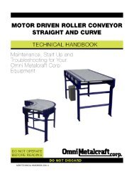
BELT DRIVEN LIVE ROLLER CONVEYOR STRAIGHT, V-BELT CURVE, STRAIGHT SPUR AND CURVE SPUR TECH HANDBOOK<br />
TABLE OF CONTENTS<br />
TABLE OF CONTENTS .................................................................................................................................. 2, 3<br />
GENERAL SAFETY STATEMENTS .................................................................................................................. 4<br />
-Introduction ..................................................................................................................................................... 4<br />
-Cautions, Warnings and Hazards ..................................................................................................................... 4<br />
SAFETY INFORMATION ............................................................................................................................... 5<br />
-Safety Labels .................................................................................................................................................... 5, 6<br />
-Installation Safety ............................................................................................................................................ 7<br />
-Electrical Safety ................................................................................................................................................ 8<br />
-Operational Safety ........................................................................................................................................... 9<br />
-Maintenance and Service Safety...................................................................................................................... 10, 11<br />
-<strong>BDLR</strong> Safety Instructions .................................................................................................................................. 12<br />
RECEIVING AND INSPECTION ...................................................................................................................... 13<br />
-Returns, Damages and Shortages ................................................................................................................... 13<br />
-Removal of Crating .......................................................................................................................................... 13<br />
GENERAL INSTALLATION ............................................................................................................................ 14<br />
-Understanding Pop-Out Rollers ....................................................................................................................... 14<br />
-Belt Lacing ........................................................................................................................................................ 14<br />
-Checking Unit Squareness ................................................................................................................................ 15<br />
-Squaring ........................................................................................................................................................... 15<br />
-Coupling / Attaching Bed Sections ................................................................................................................... 16<br />
LEG SUPPORTS AND INSTALLATION............................................................................................................ 17<br />
-Permanent Installation of Legs ........................................................................................................................ 17<br />
-Leg Adjustments .............................................................................................................................................. 17<br />
KNEE BRACES, CASTERS AND CEILING HANGERS ........................................................................................ 18<br />
-Installing Knee Braces and Casters .................................................................................................................. 18<br />
-Installing Ceiling Hangers ................................................................................................................................. 19<br />
MULTI-TIER SUPPORTS ............................................................................................................................... 20<br />
-Installation of Multi-Tier Supports ................................................................................................................... 20<br />
ASSEMBLY .................................................................................................................................................. 21<br />
-Straight <strong>BDLR</strong> Installation Instructions ............................................................................................................ 21-24<br />
-V-Belt Curve / Spur Installation Instructions.................................................................................................... 25-29<br />
INSTRUCTIONS FOR BELT TRACKING .......................................................................................................... 30<br />
-Belt Type 1 ....................................................................................................................................................... 30<br />
-Belt Type 2 ....................................................................................................................................................... 31<br />
PRE-START-UP OVERVIEW .......................................................................................................................... 32<br />
-Preparing for Initial Start-Up............................................................................................................................ 32<br />
-Drive Chain and Sprocket Alignment ............................................................................................................... 33<br />
-Drive Chain and Sprocket Tension ................................................................................................................... 34<br />
-Gear Reducer Vent Plug ................................................................................................................................... 34<br />
MAINTENANCE ........................................................................................................................................... 35<br />
-Inspection and Lubrication .............................................................................................................................. 35<br />
-Maintenance Schedules ................................................................................................................................... 36<br />
-Replacing V-Belt ............................................................................................................................................... 37<br />
-Report on Miscellaneous Maintenance Performed ......................................................................................... 38<br />
<strong>BDLR</strong> TECHNICAL HANDBOOK 2013.1<br />
2
BELT DRIVEN LIVE ROLLER CONVEYOR STRAIGHT, V-BELT CURVE, STRAIGHT SPUR AND CURVE SPUR TECH HANDBOOK<br />
TABLE OF CONTENTS (Continued)<br />
TROUBLESHOOTING AND REPLACEMENT PARTS ........................................................................................ 39<br />
-Troubleshooting ............................................................................................................................................... 39, 40<br />
PARTS LISTS ................................................................................................................................................ 41<br />
-<strong>BDLR</strong> Straight ................................................................................................................................................... 41<br />
-<strong>BDLR</strong> V-Belt Curve ............................................................................................................................................ 42, 43<br />
-<strong>BDLR</strong> V-Belt Straight Spur ................................................................................................................................ 44-46<br />
-<strong>BDLR</strong> V-Belt Curve Spur ................................................................................................................................... 47,48<br />
NOTES ........................................................................................................................................................ 49<br />
WARRANTY ................................................................................................................................................ 50<br />
<strong>BDLR</strong> TECHNICAL HANDBOOK 2013.1<br />
3
BELT DRIVEN LIVE ROLLER CONVEYOR STRAIGHT, V-BELT CURVE, STRAIGHT SPUR AND CURVE SPUR TECH HANDBOOK<br />
GENERAL SAFETY STATEMENTS<br />
IMPORTANT<br />
REQUIRED READING!<br />
¡IMPORTANTE!<br />
¡LECTURA OBLIGATORIA!<br />
To ensure this quality product is safely and correctly utilized, all instructions within this manual must be read and<br />
understood prior to equipment start-up. Be aware of all safety labels on machinery. If you do not understand any<br />
of the safety instructions or feel there may be safety labels missing, contact your supervisor or product<br />
supplier immediately!<br />
Para garantizar que este producto de calidad se utilice correctamente y con seguridad, es necesario leer y<br />
comprender las instrucciones incluidas en este manual, antes de comenzar a utilizar el equipo. Esté atento a<br />
todas las etiquetas de seguridad que se encuentran en las máquinas. Si no entiende alguna de las instrucciones<br />
de seguridad o considera que faltan algunas etiquetas de seguridad, ¡comuníquese inmediatamente con su<br />
supervisor o proveedor del producto!<br />
COMPLIANCE WITH SAFETY STANDARDS<br />
Compliance with safety standards, including federal, state and local codes or regulations is the responsibility of the conveyor<br />
purchaser(s). Placement of guards, safety labels and other safety equipment is dependent upon the area and use to which the<br />
system is applied. A safety study should be made of the conveyor application by the purchaser(s). It is the purchaser’s<br />
responsibility to provide any additional guards, safety labels or other safety equipment deemed necessary based on this<br />
safety study.<br />
The information contained in this safety manual is correct at the time of printing. Due to the continuing development of<br />
product lines, changes in specifications are inevitable. The company reserves the right to implement such changes without<br />
prior notice.<br />
If you suspect fire hazards, safety hazards, dangers towards health or any other job safety concerns,<br />
consult your federal, state or local codes.<br />
Certain safety information in this document was reprinted from ASME B20.1-2000 by permission of The<br />
American Society of Mechanical Engineers. All rights reserved.<br />
Inspect equipment for safety labels. Make sure personnel are aware of and follow safety instructions.<br />
Maintain an orderly environment in the vicinity of the conveyor at all times. Clean up spilled materials or<br />
lubricants immediately.<br />
All personnel shall be instructed regarding the necessity for continuous care and attention to safety<br />
during the operation of a conveyor. They must be trained to identify and immediately report all unsafe<br />
conditions or practices relating to the conveyor and its operation.<br />
Know your company’s machine specific Lockout / Tagout procedure. Do Not perform maintenance until<br />
electrical disconnect has been turned off!<br />
Replace all safety devices, guards and guarding prior to equipment start-up.<br />
References used for safety instructions in this manual are from: Conveyor Equipment Manufacturers Association (CEMA) and The<br />
American Society of Mechanical Engineers (ASME)<br />
4<br />
<strong>BDLR</strong> TECHNICAL HANDBOOK 2013.1
BELT DRIVEN LIVE ROLLER CONVEYOR STRAIGHT, V-BELT CURVE, STRAIGHT SPUR AND CURVE SPUR TECH HANDBOOK<br />
SAFETY INFORMATION: SAFETY LABELS<br />
Safety labels have been placed at various points on the equipment to alert everyone of potential dangers. Inspect<br />
equipment for proper position of safety labels and make sure all personnel are aware of the labels and obey their<br />
warnings. As mentioned in the previous section, a safety study should be made of the conveyor application by the<br />
purchaser(s). It is the purchaser’s responsibility to provide any additional guards, safety labels or other safety<br />
equipment deemed necessary based on this safety study. The following pages contain typical safety labels that<br />
may have been attached to your equipment.<br />
#110479 ( 5” x 2 1/2” )<br />
Placed on terminating ends (both ends) where there are exposed<br />
moving parts which must be unguarded to facilitate function, i.e.<br />
rollers, pulleys, shafts, chains, etc.<br />
#113529 (5” X 2 1/2” )<br />
Placed next to drive (both sides) to warn personnel that the lineshaft<br />
conveyor utilizes a rotating shaft which may be hazardous if hair or loose<br />
clothing become entangled around the rotating shaft. Also used on any<br />
other conveyors where the exposed shaft may create similar hazards.<br />
#111744 (5” X 2 1/2” )<br />
General warning to personnel that the equipment’s moving parts,<br />
which operate unguarded by necessity or function, i.e., air cylinders,<br />
etc., create hazards to be avoided.<br />
#110478 ( 5” X 2 1/2” )<br />
Placed on all chain guards to warn that operation of the machinery with<br />
guards removed would expose chains, belts, gears, shafts, pulleys,<br />
couplings, etc. which create hazards.<br />
#111752 ( 5” X 2 1/2” )<br />
Placed on max. of 20’ centers (both sides) along conveyors which<br />
provide surfaces and profiles attractive, but hazardous, for climbing,<br />
sitting, walking or riding.<br />
#113513 ( 5” X 2 1/2” )<br />
Placed on chain guard base so label is visible when guard cover is removed.<br />
#113528 ( 5” X 2 1/2” )<br />
Placed next to drive (both sides) to warn maintenance personnel that<br />
conveyors must be shut off and locked out prior to servicing. Examples:<br />
drives, take-ups, and lubrication points, which require guard removal.<br />
#111870 ( 5” X 3” )<br />
General warning of pinch point hazards.<br />
<strong>BDLR</strong> TECHNICAL HANDBOOK 2013.1<br />
5<br />
(Continued on next page)
BELT DRIVEN LIVE ROLLER CONVEYOR STRAIGHT, V-BELT CURVE, STRAIGHT SPUR AND CURVE SPUR TECH HANDBOOK<br />
SAFETY INFORMATION: SAFETY LABELS (Continued)<br />
#111750 ( 1 3/4” x 1 1/4” )<br />
Generally placed on smaller guards to<br />
alert personnel of potential danger if<br />
guard is removed and power is not<br />
locked out.<br />
#111749 ( 3” x 1 1/4” )<br />
Placed on shipping brace which stabilizes<br />
equipment during shipping. Brace must be<br />
removed before operating! May cause severe<br />
injury if not removed.<br />
#110491 (10” x 7” )<br />
Placed on equipment where conveyors may<br />
start without warning.<br />
<strong>BDLR</strong> TECHNICAL HANDBOOK 2013.1<br />
6
BELT DRIVEN LIVE ROLLER CONVEYOR STRAIGHT, V-BELT CURVE, STRAIGHT SPUR AND CURVE SPUR TECH HANDBOOK<br />
SAFETY INFORMATION: INSTALLATION SAFETY<br />
1) LOADING / UNLOADING<br />
Have trained personnel load or unload equipment. The conveyor must be properly handled when transferring<br />
from the unloading area to final site location to prevent damage.<br />
2) GUARDS / GUARDING<br />
Interfacing of Equipment. When two or more pieces of equipment are interfaced, special attention shall be<br />
given to the interfaced area to ensure the presence of adequate guarding<br />
and safety devices.<br />
Guarding Exceptions. Wherever conditions prevail that would require<br />
guarding under this standard but such guarding would render the conveyor<br />
unusable, seek guidance from your safety professional.<br />
3) ANCHORING<br />
DO NOT operate conveyor unless it is properly anchored. Serious injury or death may result.<br />
4) SAFETY WARNING<br />
Install all safety devices, guards and guarding prior to equipment start-up.<br />
<strong>BDLR</strong> TECHNICAL HANDBOOK 2013.1<br />
7
BELT DRIVEN LIVE ROLLER CONVEYOR STRAIGHT, V-BELT CURVE, STRAIGHT SPUR AND CURVE SPUR TECH HANDBOOK<br />
SAFETY INFORMATION: ELECTRICAL SAFETY<br />
1) ELECTRICAL CODE<br />
All electrical installations and wiring shall conform to federal, state and local codes.<br />
When conveyor operation is not required for a maintenance procedure,<br />
electrical power must be turned off and locked / tagged out following your<br />
company’s machine specific procedure.<br />
2) CONTROL STATION<br />
Control stations should be so arranged and located that the operation of the affected equipment is visible from<br />
them. Control stations shall be clearly marked or labeled to indicate the function controlled.<br />
A conveyor that would cause injury when started shall not be started until personnel in the area are alerted by a<br />
signal or by a designated person that the conveyor is about to start.<br />
Where system function would be seriously hindered or adversely affected by the required time delay, or where the<br />
intent of the warning may be misinterpreted (i.e., a work area with many different conveyors and allied devices), a<br />
clear, concise and legible warning sign needs to be provided. The warning sign shall indicate that conveyors and<br />
allied equipment may be started at any time, that danger exists and that personnel must keep clear. These<br />
warning signs shall be provided along the conveyor at areas not guarded by position or location.<br />
Remotely and automatically controlled conveyors, and conveyors where operator stations are not manned or are<br />
beyond voice or visual contact from drive areas, loading areas, transfer points and other potentially hazardous<br />
locations on the conveyor path not guarded by location, position or guards shall be furnished with emergency stop<br />
buttons, pull cords, limit switches or similar emergency stop devices.<br />
All such emergency stop devices shall be easily identifiable in the immediate vicinity of such locations unless<br />
guarded by location, position or guards. Where the design, function and operation of such conveyor clearly is not<br />
hazardous to personnel, an emergency stop device is not required.<br />
The emergency stop device shall act directly on the control of the conveyor concerned and shall not depend on the<br />
stopping of any other equipment. The emergency stop devices shall be installed so that they cannot be overridden<br />
from other locations.<br />
Inactive and unused actuators, controllers and wiring should be removed from control stations and panel board,<br />
together with obsolete diagrams, indicators, control labels and other material that might confuse the operator.<br />
3) SAFETY DEVICES<br />
All safety devices, including wiring of electrical safety devices, shall be arranged to operate such that a power<br />
failure or failure of the device itself will not result in a hazardous condition.<br />
4) EMERGENCY STOPS AND RESTARTS<br />
Conveyor controls shall be so arranged that, in case of emergency stop, manual reset or start at the location<br />
where the emergency stop was initiated shall be required for the conveyor(s) and associated equipment to resume<br />
operation.<br />
Before restarting a conveyor that has been stopped because of an emergency, an inspection of the conveyor shall<br />
be made and the cause of the stoppage determined. The starting device and electrical power must be turned off<br />
and locked / tagged out according to your company’s machine specific procedure before any attempt is made to<br />
remove the cause of the stoppage, unless operation is necessary to determine the cause or to safely remove the<br />
stoppage.<br />
5) SAFETY WARNING<br />
Replace all safety devices, guards and guarding prior to equipment start-up.<br />
8<br />
<strong>BDLR</strong> TECHNICAL HANDBOOK 2013.1
BELT DRIVEN LIVE ROLLER CONVEYOR STRAIGHT, V-BELT CURVE, STRAIGHT SPUR AND CURVE SPUR TECH HANDBOOK<br />
SAFETY INFORMATION: OPERATIONAL SAFETY<br />
Only trained, qualified personnel shall be permitted to operate a conveyor. Training shall include instruction in<br />
operation under normal conditions and emergency situations.<br />
Where safety is dependent upon stopping / starting devices, they shall be kept free of obstructions to permit<br />
access.<br />
The area around loading and unloading points shall be kept clear of obstructions that could endanger personnel.<br />
Do not ride the load-carrying element of a conveyor under any<br />
circumstances, unless the conveyor is designed and equipped with<br />
safety and control devices intended to carry personnel. For no<br />
reason shall a person ride any element of a vertical conveyor.<br />
Warning labels reading “DO NOT RIDE CONVEYOR” shall be affixed<br />
by the owner of the conveyor.<br />
Personnel working on or near a conveyor shall be instructed as to the location and operation of pertinent<br />
stopping devices.<br />
A conveyor shall be used to transport only a load that it is designed to handle safely.<br />
Under no circumstances shall the safety characteristics of the conveyor be altered.<br />
Routine inspections and preventative and corrective maintenance programs shall be conducted to ensure<br />
that all safety features and guards are retained and function properly. Inspect equipment for safety labels. Make<br />
sure personnel are aware of and follow safety label instructions.<br />
Alert all personnel to the potential hazard of entanglement in<br />
conveyors caused by items such as long hair, loose clothing and<br />
jewelry.<br />
SAFETY WARNING<br />
Replace all safety devices, guards and guarding prior to<br />
equipment start-up.<br />
<strong>BDLR</strong> TECHNICAL HANDBOOK 2013.1<br />
9
BELT DRIVEN LIVE ROLLER CONVEYOR STRAIGHT, V-BELT CURVE, STRAIGHT SPUR AND CURVE SPUR TECH HANDBOOK<br />
SAFETY INFORMATION: MAINTENANCE / SERVICE SAFETY<br />
ELECTRICAL POWER MUST BE TURNED OFF AND LOCKED / TAGGED OU T following<br />
your company’s machine specific procedures when servicing conveyor to prevent accidental<br />
restarting by other persons or interconnecting equipment (when used).<br />
1) MAINTENANCE (REPAIR)<br />
Maintenance and service shall be performed by trained, qualified personnel only.<br />
Where lack of maintenance and service would cause a hazardous condition, the user shall establish a<br />
maintenance program to ensure that conveyor components are maintained in a condition that does not<br />
constitute a hazard to personnel.<br />
No maintenance or service shall be performed when a conveyor is in operation. See “Lubrication” and<br />
“Adjustment or Maintenance During Operation” for exceptions.<br />
When a conveyor is stopped for maintenance or service, the starting devices, prime mover, powered<br />
accessories or electrical must be locked / tagged out in accordance with a formalized procedure designed to<br />
protect all persons or groups involved with the conveyor against an unexpected restart. Personnel should be<br />
alerted to the hazard of stored energy, which may exist after the power source is locked out. All safety<br />
devices and guards shall be replaced before starting equipment for normal operation.<br />
2) ADJUSTMENT OR MAINTENANCE DURING OPERATION<br />
When adjustments or maintenance must be done while equipment is in operation, only trained, qualified<br />
personnel who are aware of the hazards of the conveyor in motion shall be allowed to make adjustments,<br />
perform maintenance or service.<br />
Conveyors shall NOT be maintained or serviced while in operation unless proper maintenance or service<br />
requires the conveyor to be in motion. If conveyor operation is required, personnel shall be made aware of<br />
the hazards and how the task may be safely accomplished.<br />
3) LUBRICATION<br />
Conveyors shall NOT be lubricated while in operation unless it is impractical to shut them down for<br />
lubrication. Only trained and qualified personnel who are aware of the hazards of the conveyor in motion shall<br />
be allowed to lubricate a conveyor that is operating.<br />
Where the drip of lubricants or process liquids on the floor constitutes a hazard, drip pans or other means of<br />
eliminating the hazard must be provided by purchaser(s).<br />
4) MAINTENANCE OF GUARDS AND SAFETY DEVICES<br />
Guards and safety devices shall be maintained in a serviceable and operational condition. Warning signs are<br />
the responsibility of the owner of the conveyor and must be maintained in a legible / operational condition.<br />
<strong>BDLR</strong> TECHNICAL HANDBOOK 2013.1<br />
10
BELT DRIVEN LIVE ROLLER CONVEYOR STRAIGHT, V-BELT CURVE, STRAIGHT SPUR AND CURVE SPUR TECH HANDBOOK<br />
SAFETY INFORMATION: MAINTENANCE / SERVICE SAFETY (Continued)<br />
5) INSPECTIONS<br />
Routine inspections with preventative and /or corrective maintenance programs shall be conducted to ensure<br />
that all safety features and devices are maintained and function properly.<br />
All personnel shall inspect for hazardous conditions at all times. Remove sharp edges or protruding objects.<br />
Repair or replace worn or damaged parts immediately.<br />
6) CLEANING<br />
Where light cleaning and/or casing cleaning are required, they shall be performed by trained personnel. The<br />
conveyor electrical power must be turned off and locked / tagged out following your company’s machine<br />
specific procedures. Special attention may be required at feed and discharge points.<br />
7) SAFETY WARNING<br />
Replace all safety devices, guards and guarding prior to equipment start-up.<br />
<strong>BDLR</strong> TECHNICAL HANDBOOK 2013.1<br />
11
BELT DRIVEN LIVE ROLLER CONVEYOR STRAIGHT, V-BELT CURVE, STRAIGHT SPUR AND CURVE SPUR TECH HANDBOOK<br />
SAFETY INFORMATION: <strong>BDLR</strong> SAFETY INSTRUCTIONS<br />
PARTICULAR DANGER AND PINCH POINTS<br />
1) Any point at which a belt bends around a roller or pulley.<br />
2) Any point where two rollers or pulleys (sheaves for spurs) are close together and produce a “wringer” effect.<br />
3) Any point where accessories are located that also have moving parts.<br />
<strong>BDLR</strong> TECHNICAL HANDBOOK 2013.1<br />
12
BELT DRIVEN LIVE ROLLER CONVEYOR STRAIGHT, V-BELT CURVE, STRAIGHT SPUR AND CURVE SPUR TECH HANDBOOK<br />
RECEIVING AND INSPECTION: RETURNS, DAMAGES AND SHORTAGES<br />
UNCRATING CHECKLIST<br />
1) Compare the bill of lading with what you have received (including accessories).<br />
2) Examine the equipment for damage.<br />
3) Immediately report shortage or damages to the vendor and carrier.<br />
4) Obtain a signed damage report from the carrier and send a copy to the vendor.<br />
Do not attempt to modify or repair damaged equipment without authorization from vendor.<br />
Note:<br />
Do not return equipment to the factory without a written return authorization. Returns without written<br />
authorization will not be accepted.<br />
Single section<br />
Multiple sections<br />
Note: Custom products may be crated differently to fit the conveyor design.<br />
MOTOR DRIVEN ROLLER CONVEYOR STRAIGHT AND CURVE TECH HANDBOOK<br />
RECEIVING AND INSPECTION: REMOVAL OF CRATING<br />
AFTER COMPLETING THE “UNCRATING CHECKLIST”<br />
1) Remove crating and packaging.<br />
2) Look for boxes, accessories, bags or components such as fasteners, manuals, guard rails etc. that may be<br />
banded or fastened to the crating material.<br />
Note: Make sure all fasteners, guards and essential components are not discarded.<br />
<strong>BDLR</strong> TECHNICAL HANDBOOK 2013.1<br />
13
BELT DRIVEN LIVE ROLLER CONVEYOR STRAIGHT, V-BELT CURVE, STRAIGHT SPUR AND CURVE SPUR TECH HANDBOOK<br />
GENERAL INSTALLATION: UNDERSTANDING POP-OUT ROLLERS<br />
POP-OUT ROLLERS<br />
A special load carrying roller mounted in such a manner as to pop out when foreign objects are introduced<br />
between the belt and the roller.<br />
BELT DRIVEN LIVE ROLLER CONVEYOR STRAIGHT, V-BELT CURVE, STRAIGHT SPUR AND CURVE SPUR TECH HANDBOOK<br />
GENERAL INSTALLATION: BELT LACING (STRAIGHT CONVEYOR)<br />
BELT LACING<br />
The conveyor belt has been cut to the proper length and lacing has been installed at the factory. To install, follow<br />
these steps:<br />
1) Thread the belt through the conveyor as shown in on page 22 of this handbook.<br />
2) Pull the ends together and insert the lacing pin as shown.<br />
3) Adjust the tension with the take-up pulley or tail pulley. Keep the pulley square by moving both tension bolts<br />
an equal amount. Maintain enough tension so that the drive pulley will not slip when carrying the rated load.<br />
4) Track the belt per the instructions on page 30 and 31.<br />
TUCK PIN BACK INTO<br />
LACING, BOTH SIDES<br />
<strong>BDLR</strong> TECHNICAL HANDBOOK 2013.1<br />
14
BELT DRIVEN LIVE ROLLER CONVEYOR STRAIGHT, V-BELT CURVE, STRAIGHT SPUR AND CURVE SPUR TECH HANDBOOK<br />
GENERAL INSTALLATION: CHECKING UNIT SQUARENESS<br />
SQUARING<br />
Frame squareness can be checked by using a simple right angle square as shown or by measuring from the same<br />
points diagonally, corner to corner.<br />
Note:<br />
Make sure frames are square<br />
(as shown) or products will<br />
skew and tumble from the<br />
conveyor. Failure to square<br />
frames may also cause<br />
premature conveyor wear<br />
and failure.<br />
BELT DRIVEN LIVE ROLLER CONVEYOR STRAIGHT, V-BELT CURVE, STRAIGHT SPUR AND CURVE SPUR TECH HANDBOOK<br />
GENERAL INSTALLATION: SQUARING<br />
SQUARING CONVEYOR<br />
Bolt-together <strong>BDLR</strong> conveyor frames may be brought square utilizing the Squaring Rod Assembly provided with<br />
the conveyor. Attach the Squaring Rod Assembly angle brackets to the conveyor side frames as shown below and<br />
adjust the threaded rod until frames are squared. Excess (protruding) threaded rod should be cut off after<br />
installation.<br />
SQUARING ROD<br />
ADJUSTMENT BRACKET<br />
Note:<br />
Only trained professionals<br />
should attempt to square up<br />
a conveyor. If frames have<br />
been damaged in freight,<br />
follow the “returns, damages<br />
and shortages” protocol on<br />
page 13.<br />
BOTTOM VIEW OF CONVEYOR<br />
<strong>BDLR</strong> TECHNICAL HANDBOOK 2013.1<br />
15
BELT DRIVEN LIVE ROLLER CONVEYOR STRAIGHT, V-BELT CURVE, STRAIGHT SPUR AND CURVE SPUR TECH HANDBOOK<br />
GENERAL INSTALLATION: COUPLING / ATTACHING BED SECTIONS<br />
COUPLING<br />
Couple the sections using the fasteners provided per the drawing below.<br />
Note:<br />
For ease of installation, mount legs on each conveyor section prior to coupling.<br />
<strong>BDLR</strong> TECHNICAL HANDBOOK 2013.1<br />
16
BELT DRIVEN LIVE ROLLER CONVEYOR STRAIGHT, V-BELT CURVE, STRAIGHT SPUR AND CURVE SPUR TECH HANDBOOK<br />
LEG SUPPORTS AND INSTALLATION<br />
PERMANENT INSTALLATION OF LEGS<br />
Secure leg supports to the floor utilizing the lag holes in the adjustable leg boot.<br />
SIDE FRAMES<br />
Note:<br />
Make sure the conveyor is<br />
level by placing a level on the<br />
conveyor side frames. If the<br />
conveyor is not level, adjust<br />
the legs appropriately as<br />
shown below.<br />
LAG HOLES<br />
LEG ADJUSTMENT: BOLT-TOGETHER LEGS<br />
1) The conveyor electrical power must be turned off and<br />
locked / tagged out following your company’s machine<br />
specific procedures.<br />
2) Remove all load from the conveyor.<br />
3) Position conveyor in the location to be installed.<br />
4) Support conveyor section with jack, hoist or forklift.<br />
5) Carefully loosen the fasteners within the slots.<br />
6) Lift or lower conveyor until it is at the desired height.<br />
7) Ensure that the conveyor is completely level. (reference<br />
leveling note below)<br />
8) Tighten fasteners using torque appropriate for each<br />
fastener’s size and grade. (grade 5 fasteners provided)<br />
HEX HEAD<br />
CAP SCREWS<br />
PIVOT<br />
BRACKET<br />
UPRIGHT<br />
BOOT<br />
Note:<br />
Only qualified installation<br />
professionals should level<br />
and install conveyor.<br />
<strong>BDLR</strong> TECHNICAL HANDBOOK 2013.1<br />
17
BELT DRIVEN LIVE ROLLER CONVEYOR STRAIGHT, V-BELT CURVE, STRAIGHT SPUR AND CURVE SPUR TECH HANDBOOK<br />
KNEE BRACES, CASTERS AND CEILING HANGERS: INSTALLING KNEE BRACES<br />
INSTALLING KNEE BRACES<br />
1) After leg supports are set in place, attach the<br />
brace bracket.<br />
2) Attach knee brace angle to the leg support<br />
and brace bracket.<br />
(knee brace angle may need to be cut, drilled and<br />
trimmed for proper fit and to eliminate<br />
interference with adjacent equipment)<br />
Note:<br />
Knee braces are recommended when the<br />
conveyor height exceeds 36” and/or when<br />
additional stability is needed.<br />
DETAIL DESCRIPTION<br />
1 UPRIGHT<br />
2 SPREADER<br />
3 BRACE BRACKET<br />
4 KNEE BRACE ANGLE<br />
5 PIVOT BRACKET<br />
6 FOOT<br />
7 HEX HEAD CAP SCREW<br />
MOTOR DRIVEN ROLLER CONVEYOR STRAIGHT AND CURVE TECH HANDBOOK<br />
KNEE BRACES, CASTERS AND CEILING HANGERS: INSTALLING CASTERS<br />
NOTE: CUSTOMER TO LOCATE<br />
AND DRILL IF NECSSARY<br />
INSTALLING CASTERS<br />
Once in position, casters<br />
should be locked until<br />
conveyor needs to be<br />
moved again.<br />
Note:<br />
Leg supports with casters<br />
follow similar installation<br />
instructions as standard leg<br />
supports and knee braces.<br />
<strong>BDLR</strong> TECHNICAL HANDBOOK 2013.1<br />
18<br />
DETAIL DESCRIPTION<br />
1 UPRIGHT<br />
2 SPREADER<br />
3 BRACE BRACKET<br />
4 KNEE BRACE ANGLE<br />
5 PIVOT BRACKET<br />
6 FOOT<br />
7 Z-PLATE<br />
8 PHENOLIC CASTER<br />
9 HEX HEAD CAP SCREW
BELT DRIVEN LIVE ROLLER CONVEYOR STRAIGHT, V-BELT CURVE, STRAIGHT SPUR AND CURVE SPUR TECH HANDBOOK<br />
KNEE BRACES, CASTERS AND CEILING HANGERS: INSTALLING CEILING HANGERS<br />
INSTALLING CEILING HANGERS<br />
When using conveyors in an overhead scenario, mount hangers at section joints.<br />
Note:<br />
When installing ceiling hangers,<br />
refer to local building codes to<br />
ensure that materials comply.<br />
Only experienced material handling<br />
installers should attempt to install<br />
conveyors.<br />
CONVEYOR SECTION<br />
DETAIL DESCRIPTION<br />
1 HANGER CHANNEL<br />
2 PIPE SPREADER<br />
3 THREADED ROD<br />
4 U-BOLT<br />
5 WHIZ NUT<br />
6 HEX HEAD CAP SCREW<br />
7 HEX NUT<br />
8 LOCK WASHER<br />
<strong>BDLR</strong> TECHNICAL HANDBOOK 2013.1<br />
19
BELT DRIVEN LIVE ROLLER CONVEYOR STRAIGHT, V-BELT CURVE, STRAIGHT SPUR AND CURVE SPUR TECH HANDBOOK<br />
MULTI-TIER SUPPORTS: INSTALLATION OF MULTI-TIER SUPPORTS<br />
INSTALLING MULTI-TIER SUPPORTS<br />
1) Remove the upper spreader (detail 2) from support.<br />
2) Lower the conveyor section onto the lower spreader (detail 2) and attach using supplied fasteners.<br />
3) Check for appropriate elevation and attach the knee bracket assembly (detail 3,4,6,7,8).<br />
4) For upper conveyor assembly, replace upper spreader and repeat steps 2 and 3.<br />
5) Make sure all multi-tier supports are in line and square prior to conveyor start-up.<br />
Note: Make sure that the conveyor is stable prior<br />
to multi-tier assembly. Use of a forklift or crane may<br />
be required to ensure safe handling. Only experienced<br />
installation professionals should install conveyor.<br />
DETAIL DESCRIPTION<br />
1 UPRIGHT<br />
2 SPREADER<br />
3 BRACE BRACKET<br />
4 KNEE BRACE ANGLE<br />
5 FOOT WELDMENT<br />
6 WHIZ NUT<br />
7 HEX HEAD CAP SCREW<br />
8 FLAT WASHER<br />
<strong>BDLR</strong> TECHNICAL HANDBOOK 2013.1<br />
20
BELT DRIVEN LIVE ROLLER CONVEYOR STRAIGHT, V-BELT CURVE, STRAIGHT SPUR AND CURVE SPUR TECH HANDBOOK<br />
GENERAL INSTALLATION: STRAIGHT <strong>BDLR</strong> INSTALLATION INSTRUCTIONS<br />
<strong>BDLR</strong> STRAIGHT TRANSPORATION AND MINIMUM PRESSURE INSTALLATION INSTRUCTIONS<br />
1) Snap a chalk line on the floor along the conveyor center line. All installation should use this as a base line.<br />
2) Fasten floor supports to drive section as shown below. Secure supports to approximate desired height.<br />
3) Attach supports to intermediate and take-up sections. Secure supports to approximate desired height.<br />
4) Attach intermediate sections one at a time to drive section assembly. When all intermediate sections are<br />
assembled attach take-up section assembly. Adjust supports to exact height required.<br />
END DRIVE<br />
PRODUCT FLOW<br />
BELT DIRECTION<br />
DRIVE SECTION<br />
ASSEMBLY<br />
INTERMEDIATE<br />
SECTION<br />
TAKE-UP SECTION<br />
ASSEMBLY<br />
CENTER DRIVE<br />
PRODUCT FLOW<br />
BELT DIRECTION<br />
INTERMEDIATE<br />
SECTION<br />
INTERMEDIATE<br />
SECTION<br />
TAKE-UP SECTION<br />
ASSEMBLY<br />
DRIVE SECTION<br />
ASSEMBLY<br />
TAKE-UP SECTION<br />
ASSEMBLY<br />
<strong>BDLR</strong> TECHNICAL HANDBOOK 2013.1<br />
21
BELT DRIVEN LIVE ROLLER CONVEYOR STRAIGHT, V-BELT CURVE, STRAIGHT SPUR AND CURVE SPUR TECH HANDBOOK<br />
GENERAL INSTALLATION: STRAIGHT <strong>BDLR</strong> INSTALLATION INSTRUCTIONS<br />
5) Loop belt over snub rollers, return rollers and end pulleys as shown below. Bring laced ends together and<br />
thread steel pin through loops. Belts can be supplied with two types of lacing, “Standard” and “Cover-Flap<br />
Lace”, position the flap in relationship to flow according to view circle A-A below. It is recommended for the<br />
flap to be glued after installation.<br />
CENTER DRIVE<br />
PRODUCT FLOW<br />
END PULLEY<br />
TREAD ROLLERS<br />
RETURN ROLLER<br />
END PULLEY<br />
SNUB<br />
ROLLER<br />
SNUB<br />
ROLLER<br />
DRIVE<br />
PULLEY<br />
PRESSURE<br />
ROLLER<br />
SNUB ROLLER<br />
END DRIVE<br />
PRODUCT FLOW<br />
DRIVE PULLEY<br />
TREAD ROLLERS<br />
TAKE-UP<br />
PULLEY<br />
PRODUCT FLOW<br />
SMOOTH SIDE OF BELT<br />
(TOP SIDE)<br />
PRESSURE ROLLER<br />
SNUB ROLLER<br />
BELT FLOW<br />
“STANDARD” LACING<br />
“COVER-FLAP” LACING<br />
6) Assemble tread rollers into conveyor. (These rollers are shipped loose.)<br />
7) Remove excess slack from belt by adjusting the take-up pulley. Do not over tighten belt because it will be<br />
difficult, if not impossible, to track the belt.<br />
8) Loosen bolts in the pressure roller brackets and raise pressure rollers to increase the driving force of the<br />
tread rollers. This should be set to the minimum amount required to move the product. Excess pressure is<br />
unnecessary and will cause premature belt and frame wear.<br />
9) Check all frame sections, end units, drive units, etc. for squareness (page 15). All snub rollers and pulleys<br />
must be set square with the frame before making any belt adjustments.<br />
10) See belt tracking instructions for Type 1 Belt on page 30 for End Drive or Type 2 Belt on page 31 for Center<br />
Drive.<br />
<strong>BDLR</strong> TECHNICAL HANDBOOK 2013.1<br />
VIEW CIRCLE A - A<br />
22
BELT DRIVEN LIVE ROLLER CONVEYOR STRAIGHT, V-BELT CURVE, STRAIGHT SPUR AND CURVE SPUR TECH HANDBOOK<br />
GENERAL INSTALLATION: STRAIGHT <strong>BDLR</strong> INSTALLATION INSTRUCTIONS<br />
6) Assemble tread rollers into conveyor (these rollers are shipped loose). Locate the grooved tread roller and<br />
slave belts at conveyor ends as shown below in the appropriate drawing.<br />
PRODUCT FLOW PRODUCT FLOW PRODUCT FLOW<br />
SLAVE<br />
BELT<br />
TWO GROOVE<br />
TREAD ROLLER<br />
ONE GROOVE TREAD<br />
ROLLER<br />
TREAD ROLLER<br />
DRIVE SECTION END 4”<br />
PULLEY<br />
DRIVE SECTION END 8”<br />
PULLEY<br />
TAKE-UP SECTION END 4”<br />
PULLEY<br />
7) Remove excess slack from belt by adjusting the take-up pulley. Do not over tighten belt because it will be<br />
difficult, if not impossible, to track the belt.<br />
8) A) TRANSPORTATION<br />
Adjust belt pressure to tread rollers by raising pressure rollers. Loosen bolts in the pressure roller brackets.<br />
Raise brackets on both sides of conveyor until belt pressure to tread rollers is sufficient to drive largest<br />
product. Keep brackets equal and level from side to side. Retighten bolts. Note: Excess pressure is<br />
unnecessary and will cause premature belt and frame wear.<br />
TREAD ROLLER<br />
BELT<br />
RETURN ROLLER<br />
PRESSURE ROLLER<br />
PRESSURE ROLLER<br />
BRACKET<br />
<strong>BDLR</strong> TECHNICAL HANDBOOK 2013.1<br />
23
BELT DRIVEN LIVE ROLLER CONVEYOR STRAIGHT, V-BELT CURVE, STRAIGHT SPUR AND CURVE SPUR TECH HANDBOOK<br />
GENERAL INSTALLATION: STRAIGHT <strong>BDLR</strong> INSTALLATION INSTRUCTIONS<br />
8) B) MINIMUM PRESSURE<br />
While the conveyor is running, reduce pressure on all tread rollers by loosening the knurled finger nuts until<br />
there is no belt pressure driving the tread rollers. Place the heaviest product to be conveyed on the infeed<br />
end of conveyor. Increase pressure by tightening knurled finger nuts until belt pressure to tread rollers is<br />
sufficient to drive product. Keep brackets equal and level from side to side. Continue process until product<br />
has traveled the entire length of conveyor. Note: Excess pressure is unnecessary and will cause premature<br />
belt and frame wear.<br />
TREAD ROLLER<br />
BELT<br />
KNURLED FINGER NUT RETURN ROLLER PRESSURE ROLLER<br />
PRESSURE<br />
ROLLER BRACKET<br />
9) Check all frame sections, end units, drive units, etc. for squareness (page 15). All snub rollers and pulleys<br />
must be set square with the frame before making any belt adjustments.<br />
10) See belt tracking instructions for Type 1 Belt on page 30 for End Drive or Type 2 Belt on page 31 for Center<br />
Drive.<br />
<strong>BDLR</strong> TECHNICAL HANDBOOK 2013.1<br />
24
BELT DRIVEN LIVE ROLLER CONVEYOR STRAIGHT, V-BELT CURVE, STRAIGHT SPUR AND CURVE SPUR TECH HANDBOOK<br />
GENERAL INSTALLATION: V-BELT CURVE/SPUR INSTALLATION INSTRUCTIONS<br />
V-BELT DRIVEN LIVE ROLLER CURVE/SPUR INSTALLATION INSTRUCTIONS<br />
V-Belt conveyors can be connected to a wide variety of conveyors, such as other V-Belt sections, Flat-Belt Driven<br />
Live Roller, Lineshaft and Gravity Conveyor.<br />
1) Snap a chalk line on the floor along the conveyor center line. All installation should use this as a base line.<br />
2) Attach supports to both ends (tangent section) of each curve and also (1) support in center portion of curve.<br />
V-Belt Driven spurs get (1) leg only underneath head section.<br />
Note: If the V-Belt conveyor will be connecting to another V-Belt conveyor, (1) support may be placed on the<br />
splice of the two units, due to frame depths being the same. However, if it to be connected to some other type<br />
where the frame depths are different, the supports will need to be placed at the ends of both units.<br />
3) Hand tighten bolts only.<br />
4) Assemble the conveyor sections and components on the supports as shown in the assembly drawing<br />
pertaining to the type of conveyor ordered and/or system layout drawing if provided.<br />
5) Fasten sections together with end couplers and leg support pivot brackets. Hand tighten only. See figure 1A<br />
and 1B.<br />
FLAT-BELT<br />
END COUPLER<br />
V-BELT SECTION<br />
SECTION<br />
V-BELT SECTION<br />
MOUNTING<br />
BOLTS<br />
LEG SUPPORT<br />
PIVOT BRACKET<br />
FIGURE 1A<br />
FIGURE 1B<br />
6) Attach V-Belt Driven spurs to side of straight conveyor as shown in figure 2.<br />
STRAIGHT CONVEYOR<br />
V-BELT SPUR<br />
<strong>BDLR</strong> TECHNICAL HANDBOOK 2013.1<br />
FIGURE 2<br />
25<br />
MOUNTING BOLT
BELT DRIVEN LIVE ROLLER CONVEYOR STRAIGHT, V-BELT CURVE, STRAIGHT SPUR AND CURVE SPUR TECH HANDBOOK<br />
GENERAL INSTALLATION: V-BELT CURVE/SPUR INSTALLATION INSTRUCTIONS<br />
7) V-Belt curves and spurs without their own drive unit may be slaved off another V-Belt unit or Flat-Belt Driven<br />
conveyor.<br />
8) Check all frame sections, end units, etc. for squareness. All rollers, pulleys and sheaves must be square with<br />
the conveyor frame.<br />
9) Adjust elevation to desired height. Anchor floor supports securely. Level the conveyor. Tighten all bolts<br />
securely.<br />
10) Check that drive and idler shafts are square with sideframe. Belt may slip off of drive sheave if they are not<br />
square. Adjust the jack-bolt bracket next to the bearing on the outside of the conveyor to square shafts. See<br />
figure 3.<br />
11) Check and tighten all set screws.<br />
DRIVE SHEAVE<br />
BEARING<br />
FIGURE 3<br />
JACK-BOLT BRACKET<br />
SLAVE DRIVEN CURVES AND SPURS<br />
V-Belt Driven Live Roller conveyors can be connected to a wide variety of conveyors, such as other V-Belt<br />
sections, Flat-Belt Driven Live Roller, Lineshaft, Gravity conveyors, etc. V-Belt curves and spurs without their own<br />
drive may be slaved off another V-Belt unit or Flat-Belt Driven Live Roller conveyor.<br />
1) Fasten sections together with end couplers and leg support pivot brackets. Hand tighten only. See figure 1A<br />
and 1B on page 25.<br />
2) Attach guard backside to conveyor frames. Slide guard over extended shafts and attach with support<br />
brackets. Note support bracket locations for connecting (2) V-Belt units together in figure 4A and 4B for<br />
connecting V-Belt to Flat-Belt sections.<br />
3) Assemble sprockets onto shafts. Use a straight edge along the face of both sprockets to properly align. Make<br />
necessary adjustments and tighten set screws.<br />
4) Wrap chain or timing belt around sprockets. Use the supplied link to connect the chain together.<br />
5) Adjust the chain tensioner or take-up rod bracket to properly tension the chain/timing belt.<br />
6) Attach guard cover to guard backside.<br />
<strong>BDLR</strong> TECHNICAL HANDBOOK 2013.1<br />
26
3” OR 7”<br />
2” OR 6”<br />
1”<br />
BELT DRIVEN LIVE ROLLER CONVEYOR STRAIGHT, V-BELT CURVE, STRAIGHT SPUR AND CURVE SPUR TECH HANDBOOK<br />
GENERAL INSTALLATION: V-BELT CURVE/SPUR INSTALLATION INSTRUCTIONS<br />
SUPPORT<br />
BRACKET<br />
CHAIN<br />
SPROCKET<br />
CHAIN GUARD BACKSIDE<br />
CHAIN TENSIONER<br />
V-BELT CONVEYOR<br />
V-BELT CONVEYOR<br />
FIGURE 4A<br />
SLAVE KIT FOR CONNECTING (2) V-BELT UNITS<br />
TOGETHER - CHAIN DRIVEN<br />
CHAIN GUARD COVER<br />
SUPPORT BRACKET<br />
TIMING BELT<br />
SPROCKET<br />
CHAIN GUARD BACKSIDE<br />
TAKE-UP ROD<br />
BRACKET<br />
FLAT-BELT SHEAVE<br />
FIGURE 4B<br />
SLAVE KIT FOR CONNECTING V-BELT UNIT TO FLAT-<br />
BELT UNIT - TIMING BELT DRIVEN<br />
SIDE GUIDES: FIXED ANGLE / CHANNEL SIDE RAIL<br />
Attach rail to top of conveyor frame as shown in drawing.<br />
BF<br />
CHAIN GUARD COVER<br />
1 1/2”<br />
RAIL<br />
TUBE SPACER<br />
Note: Holes must be drilled in frame at time of assembly.<br />
FIGURE 5<br />
FIXED ANGLE GUARD RAIL<br />
(CHANNEL GUARD RAIL NOT SHOWN)<br />
<strong>BDLR</strong> TECHNICAL HANDBOOK 2013.1<br />
27
BELT DRIVEN LIVE ROLLER CONVEYOR STRAIGHT, V-BELT CURVE, STRAIGHT SPUR AND CURVE SPUR TECH HANDBOOK<br />
GENERAL INSTALLATION: V-BELT CURVE/SPUR INSTALLATION INSTRUCTIONS<br />
PRESSURE ADJUSTMENT<br />
V-Belt curves and spurs utilize a pressure sheave to force the V-Belt into contact with the tread rollers. Slots in<br />
the inside frame of a curve and long frame of a spur allow the sheaves to be adjusted up and down to obtain the<br />
correct amount of pressure to the tread rollers. Apply only enough pressure to drive the heaviest product to be<br />
conveyed. See figure 6.<br />
CAUTION: APPLYING TOO MUCH PRESSURE CAN CAUSE THE CONVEYOR TO STALL OUT.<br />
PRESSURE SHEAVE<br />
TREAD ROLLERS<br />
CORRECT<br />
INCORRECT -<br />
ADJUSTED TOO HIGH<br />
FIGURE 6<br />
<strong>BDLR</strong> TECHNICAL HANDBOOK 2013.1<br />
28
BELT DRIVEN LIVE ROLLER CONVEYOR STRAIGHT, V-BELT CURVE, STRAIGHT SPUR AND CURVE SPUR TECH HANDBOOK<br />
GENERAL INSTALLATION: V-BELT CURVE/SPUR INSTALLATION INSTRUCTIONS<br />
BELT TENSIONING (CURVES)<br />
The V-Belt must be properly tensioned to ensure the correct amount of drive pressure. A belt tensioned too<br />
much can cause the conveyor to stall out. Likewise, a belt not tensioned enough may be unable to drive the tread<br />
rollers at all.<br />
V-Belt curves have a take-up sheave located in the center of the curve that allows the belt to be tensioned.<br />
Loosen jam nuts on both ends of take-up rod and adjust sheave as shown in figure 7. If more belt take-up is<br />
required than what the take-up sheave allows, (2) idler sheaves may be moved accordingly.<br />
Note: Both idler sheaves should be moved equal distances.<br />
TAKE-UP SHEAVE<br />
TAKE-UP BRACKET LOCATED BELOW SPREADER<br />
TIGHTEN<br />
LOOSEN<br />
IDLER SHEAVE<br />
V-BELT<br />
BELT TENSIONING (SPURS)<br />
FIGURE 7<br />
V-Belt spurs have a take-up sheave located at the narrow end of the spur that allows the belt to be tensioned.<br />
Loosen jam nuts on take-up rod and adjust mounting bracket as shown in figure 8. If more belt take-up is<br />
required than what the mounting bracket allows, the snub sheave may also be adjusted.<br />
FIGURE 8<br />
MOUNTING BRACKET<br />
TAKE-UP SHEAVE<br />
V-BELT<br />
TAKE-UP BRACKET<br />
TAKE-UP ROD<br />
<strong>BDLR</strong> TECHNICAL HANDBOOK 2013.1<br />
SNUB SHEAVE<br />
29<br />
TIGHTEN<br />
LOOSEN
BELT DRIVEN LIVE ROLLER CONVEYOR STRAIGHT, V-BELT CURVE, STRAIGHT SPUR AND CURVE SPUR TECH HANDBOOK<br />
INSTRUCTIONS FOR BELT TRACKING: BELT TYPE 1<br />
Note: All snub rollers and pulleys must be set square with the frame before making any belt tracking<br />
adjustments. Mark initial belt position before beginning. Make all adjustments in small increments. CONVEYOR<br />
POWER MUST BE TURNED OFF WHEN MAKING ANY ADJUSTMENTS.<br />
BELT TYPE 1: ONE-WAY SERVICE, LEVEL WITH END DRIVE<br />
ELEVATION VIEW<br />
PRODUCT FLOW<br />
BELT DIRECTION<br />
1 2<br />
3<br />
1<br />
TOP VIEW<br />
BELT DIRECTION<br />
3<br />
2<br />
Note: If belt is running off-center to opposite than shown, adjust rollers and pulleys in opposite direction than shown.<br />
1) Run conveyor for a few minutes so the belt can take its position. Stop conveyor immediately if belt rubs<br />
against side of conveyor. If belt shifts to one side, adjust snub roller (3) to steer belt to center of take-up<br />
pulley (2).<br />
2) If belt is riding at the center of the take-up pulley (2) but not at the center of the drive pulley (1), adjust drive<br />
pulley (1) slightly as shown. The belt will travel toward the slack side.<br />
3) Adjusting the drive pulley (1) may throw off belt alignment on the take-up pulley (2). Repeat steps 1 and 2 as<br />
necessary. The belt will stretch during the first few days of operation. Adjust the take-up pulley (2) to<br />
compensate for the stretch.<br />
<strong>BDLR</strong> TECHNICAL HANDBOOK 2013.1<br />
30
BELT DRIVEN LIVE ROLLER CONVEYOR STRAIGHT, V-BELT CURVE, STRAIGHT SPUR AND CURVE SPUR TECH HANDBOOK<br />
INSTRUCTIONS FOR BELT TRACKING: BELT TYPE 2<br />
Note: All snub rollers and pulleys must be set square with the frame before making any belt tracking<br />
adjustments. Mark initial belt position before beginning. Make all adjustments in small increments. CONVEYOR<br />
POWER MUST BE TURNED OFF WHEN MAKING ANY ADJUSTMENTS.<br />
BELT TYPE 2: TWO-WAY SERVICE, LEVEL WITH CENTER DRIVE<br />
ELEVATION VIEW<br />
PRODUCT FLOW<br />
6<br />
4<br />
1<br />
7<br />
5<br />
2<br />
3<br />
4<br />
TOP VIEW - FORWARD<br />
TOP VIEW - REVERSE<br />
6<br />
5<br />
4<br />
2<br />
3<br />
7 6<br />
5 1 2 3 7<br />
FLOW<br />
FLOW<br />
Note: If belt is running off-center to opposite than shown, adjust rollers and pulleys in opposite direction than shown.<br />
FORWARD SERVICE<br />
1) Start belt for FORWARD service. Run conveyor for a few minutes so the belt can take its position. Stop<br />
conveyor immediately if belt rubs against side of conveyor. If belt shifts to one side, adjust snub rollers (4)<br />
to steer belt to center of take-up pulley (2), which in turn centers the belt onto the take-up pulley (7).<br />
Reversing belts may require that the belt run slightly off-center to one side in forward direction and to<br />
opposite side in reverse direction. This is due to the nature of the belt.<br />
2) Slight adjustment of snub roller (3) may be required to steer the return belt to center of take-up pulley (7).<br />
3) If belt is riding at the center of the take-up pulley (7) but not at the center of the take-up pulley (6), slight<br />
adjustment of take-up pulley (6) may be needed.<br />
Note: Care is required as leading the belt with this pulley may cause the belt to travel to the opposite side<br />
in REVERSE service.<br />
Adjust in very small increments. The belt will stretch during the first few days of operation. Adjust the takeup<br />
pulley (1) to compensate for the stretch.<br />
REVERSE SERVICE<br />
1) Tracking for REVERSE service should not be done until preliminary FORWARD service has been completed. If<br />
belt shifts to one side, adjust take-up pulley (1) to steer belt to center of drive pulley (2), which in turn<br />
centers the belt onto take-up pulley (6).<br />
2) Slight adjustment of snub roller (5) may be required to steer belt to center of take-up pulley (6).<br />
3) If belt is riding at the center of take-up pulley (6), but not at the center of take-up pulley (7), slight<br />
adjustment of take up pulley (7) may be needed.<br />
Note: Care is required as leading the belt with this pulley may cause the belt to travel to the opposite side<br />
in FORWARD service.<br />
Adjust in very small increments. The belt will stretch during the first few days of operation. Adjust the takeup<br />
pulley (1) to compensate for the stretch.<br />
<strong>BDLR</strong> TECHNICAL HANDBOOK 2013.1<br />
31
BELT DRIVEN LIVE ROLLER CONVEYOR STRAIGHT, V-BELT CURVE, STRAIGHT SPUR AND CURVE SPUR TECH HANDBOOK<br />
PRE-START-UP OVERVIEW: PREPARING FOR INITIAL START-UP<br />
1) Review pages 7 through 12 prior to starting any equipment.<br />
2) Verify that conveyor sections, leg supports, etc. were installed properly.<br />
3) Verify that drive chains and sprockets are installed, aligned and tensioned properly<br />
4) Verify set screws are tight in sprockets, bearings and all components that have them in.<br />
5) Verify that all drive and mounted bearing bolts are fastened securely.<br />
6) Verify that all motor control wiring is connected properly.<br />
7) Verify that conveyor is not loaded with product.<br />
8) Verify that gearboxes are filled with the proper amount of oil or that they were factory filled with lube. (If<br />
your conveyor is equipped with a Boston 700 Series Reducer, it is filled with oil, sealed and lubed for life thus<br />
requiring no oil changes. Literature provided with equipment will give detailed info on gearbox lube info)<br />
9) Verify that the gearbox has necessary vent plugs installed if applicable. (If your conveyor is equipped with a<br />
Boston 700 Series Reducer, it is supplied with a PosiVent® and no vent plug is required. Literature provided<br />
with equipment will give detailed info on gearbox vent plug requirements.)<br />
<strong>BDLR</strong> TECHNICAL HANDBOOK 2013.1<br />
32
BELT DRIVEN LIVE ROLLER CONVEYOR STRAIGHT, V-BELT CURVE, STRAIGHT SPUR AND CURVE SPUR TECH HANDBOOK<br />
PRE-START-UP OVERVIEW: DRIVE CHAIN AND SPROCKET ALIGNMENT<br />
DRIVE CHAIN AND SPROCKET ALIGNMENT<br />
To achieve maximum service life and efficiency from a chain drive, follow these simple guidelines:<br />
Visually inspect the roller chain, sprockets, and other components and verify that they are in good condition.<br />
Ensure that the sprockets are properly aligned.<br />
Adequately lubricate the chain.<br />
Inspect for proper chain tension.<br />
CONDITION OF COMPONENTS<br />
Shafting and bearings should be supported rigidly to maintain the initial alignment.<br />
Roller chain should be free of grit and dirt. Wash chain in kerosene when required. Relubricate.<br />
DRIVE ALIGNMENT<br />
Misalignment results in uneven loading across the width of the chain and may cause roller link-plate and sprocket<br />
tooth wear. Drive alignment involves two things: parallel shaft alignment and axial sprocket alignment.<br />
ALIGNING SHAFTS<br />
Shafts should be parallel and level. If there is axial movement of the shaft (as in the case of an electric motor),<br />
lock the shaft in the normal running position before aligning the sprockets.<br />
ALIGNING SPROCKETS<br />
Sprocket axial alignment can be checked with a straight edge which will extend across the finished sides of the<br />
two sprockets. Normally, it is good practice to align the sprockets as close to the shaft bearing as possible. For<br />
long center distances, use a taut cord, or wire long enough to extend beyond each of the sprockets.<br />
SPROCKET<br />
STRAIGHT EDGE<br />
SET SCREWS<br />
SPROCKET<br />
WARNING:<br />
Before performing any<br />
maintenance, lubrication or<br />
inspection on any powered<br />
conveyor, the electrical<br />
power must be turned off and<br />
locked / tagged out following<br />
your company’s machine<br />
specific procedure. NEVER<br />
operate the conveyor with<br />
any guard removed.<br />
<strong>BDLR</strong> TECHNICAL HANDBOOK 2013.1<br />
33
BELT DRIVEN LIVE ROLLER CONVEYOR STRAIGHT, V-BELT CURVE, STRAIGHT SPUR AND CURVE SPUR TECH HANDBOOK<br />
PRE-START-UP OVERVIEW: DRIVE CHAIN AND SPROCKET TENSION<br />
INSTALLING THE CHAIN<br />
Recheck all preceding adjustments for alignment and make certain all setscrews, bolts and nuts are tight. Fit<br />
chain around both sprockets and bring the free ends together on one sprocket for connection. The sprocket teeth<br />
will locate the chain end links. Install the connecting link, connecting link cover plate and the spring clip or cotter<br />
pins. On larger pitch chains or heavy multiple strand, it may be necessary to lock the sprockets for this operation.<br />
CHAIN TENSION<br />
Check chain tension to be certain the slack span has an approximate 2% mid-span movement.<br />
CHAIN TOO TIGHT<br />
CHAIN TOO LOOSE<br />
CORRECT SLACK<br />
SPROCKET CENTERS<br />
Requires extra power and<br />
causes excessive wear<br />
Causes excessive wear and<br />
excessive noise<br />
Approximately 2% of<br />
sprocket centers<br />
CHAIN DRIVEN LIVE ROLLER CONVEYOR STRAIGHT AND CURVE TECH HANDBOOK<br />
PRE-START-UP OVERVIEW: GEAR REDUCER VENT PLUG<br />
PosiVent®<br />
<strong>Omni</strong> <strong>Metalcraft</strong> <strong>Corp</strong>. standardly supplies the<br />
Boston Gear PosiVent® option for all current<br />
700 series styles and configurations. This<br />
specially-designed internal pressure<br />
equalization system allows the gearbox to<br />
operate in all environments without the use<br />
of conventional pressure vents. The unique<br />
design comes complete with Klubersynth UH1<br />
6-460 lubrication pre-filled for all mounting<br />
positions. Unlike competitive versions, this<br />
unique single seam design allows for easy<br />
installation and extended life. This means<br />
longer trouble-free operation with virtually<br />
no maintenance.<br />
<strong>BDLR</strong> TECHNICAL HANDBOOK 2013.1<br />
34
BELT DRIVEN LIVE ROLLER CONVEYOR STRAIGHT, V-BELT CURVE, STRAIGHT SPUR AND CURVE SPUR TECH HANDBOOK<br />
MAINTENANCE: INSPECTION AND LUBRICATION<br />
CARE AND MAINTENANCE OF CHAIN<br />
Proper maintenance of any chain should include correct lubrication, periodic inspection and proper adjustment<br />
for normal wear. Periodic inspection of the chain and sprockets is required to detect any deviation from normal<br />
wear before serious damage takes place. The cost of such inspection is repaid many times in extended chain life<br />
and in freedom from failure. No general rule can be given for the frequency of inspection. The frequency should<br />
be influenced by conditions of operation.<br />
CHAIN LUBRICATION AND ENVIRONMENT<br />
One of the most important factors in getting the best possible performance<br />
out of our drive chain is proper lubrication. A well lubricated chain will have<br />
an operating life much longer than that of an unlubricated chain. Wear<br />
between the pin and bushing causes drive chain to elongate. These parts<br />
should, therefore, be well lubricated. The gap between the roller link plate<br />
and the pin link plate on the slack side of the chain should be filled with oil.<br />
This oil forms a film which minimizes wear on the pin and bushing, thus<br />
increasing the chain’s service life. It also reduces noise and acts as a coolant<br />
when the chain runs at high speeds.<br />
PIN LINK PLATE<br />
Clean Atmosphere: Chains operating in a relatively clean atmosphere can be lubricated by brush or dripfeed<br />
oilers or by applying the lubricant manually with a brush or oil can.<br />
Atmosphere with Lint or Non-Abrasive Dust: Where large volumes of lint or non-abrasive dust are<br />
present, a brush or wiper can be used to clean the chain and apply a lubricant. Otherwise the lint or dust<br />
will clog the chain joint clearance and prevent penetration of the oil into the joints.<br />
Abrasive Atmosphere: If abrasives come in contact with chain, lubrication becomes more difficult. When<br />
lubricants are applied externally, abrasive particles tend to adhere to the chain surfaces and act as a<br />
lapping or grinding compound. Under extreme conditions it is sometimes advisable to avoid chain<br />
lubrication.<br />
Extreme Conditions: Consult a lubricant manufacturer when chains are required to operate at<br />
temperatures outside of those indicated in the chart below or if chains are used in other extreme<br />
conditions.<br />
SUGGESTED LUBRICATION<br />
Only high quality oil should be used to lubricate chain. Neither heavy oil nor grease is suitable. The lubricant<br />
should have a viscosity to enable it to reach internal surfaces under normal conditions. Lubricants suggested for<br />
specific ambient temperatures and chain speed ranges are given in the table below.<br />
TEMPERATURE<br />
CHAIN NUMBER 15° - 35° F 35° - 105° F 105° - 120° F 120° - 140° F<br />
ANSI 25 - 50 SAE10W SAE20 SAE30 SAE40<br />
ANSI 60 - 100 SAE20 SAE30 SAE40 SAE50<br />
ANSI 120 - 240 SAE30 SAE40 SAE50<br />
4" & 6" PITCH<br />
(ENGINEERED CHAIN)<br />
SAE20 SAE30 SAE40<br />
PIN<br />
ROLLER<br />
ROLLER LINK PLATE<br />
BUSHING<br />
<strong>BDLR</strong> TECHNICAL HANDBOOK 2013.1<br />
35
BELT DRIVEN LIVE ROLLER CONVEYOR STRAIGHT, V-BELT CURVE, STRAIGHT SPUR AND CURVE SPUR TECH HANDBOOK<br />
MAINTENANCE: MAINTENANCE SCHEDULES<br />
Note:<br />
Review pages 10 and 11 prior to maintaining any equipment.<br />
If equipment repair or replacement is required during inspections, thoroughly review the manufacturer’s specific<br />
product information for correct procedure.<br />
DAILY MAINTENANCE<br />
Inspect all conveyors to ensure that all guarding is securely in place.<br />
Inspect belt tracking for at least (3) full belt revolutions.<br />
WEEKLY MAINTENANCE<br />
Inspect conveyor for loose bolts and set screws.<br />
Inspect bearings, gear reducers, motors and chains for excessive noise or heat.<br />
Inspect belt to ensure that there is not excessive wear and that all splices are intact.<br />
Inspect belt tension. The tension should be enough to:<br />
A) Prevent slippage between drive pulley (sheaves for spurs) and belt under a full load.<br />
B) Force belt to conform to the crown on crowned pulleys.<br />
Inspect rollers to ensure that they rotate freely without excessive noise.<br />
MONTHLY MAINTENANCE<br />
Inspect oil level in reducer. Fill if necessary.<br />
Inspect reducer for leaking seals.<br />
Inspect conveyor for loose bolts.<br />
Inspect drive chains, jump chains and sprockets for wear, alignment and proper chain tension. For chain<br />
lubrication see page 35.<br />
QUARTERLY MAINTENANCE<br />
Grease all pulley shaft bearings.<br />
SEMI-ANNUAL MAINTENANCE<br />
Tighten all bearing set screws if not completely tight.<br />
ANNUAL MAINTENANCE<br />
Change oil in reducers. (If your conveyor is equipped with a Boston 700 Series Reducer, it is filled with oil,<br />
sealed and lubed for life thus requiring no oil changes. See manufacturer’s information for recommended<br />
lubricant at specific temperatures. This information is shipped with every reducer.)<br />
<strong>BDLR</strong> TECHNICAL HANDBOOK 2013.1<br />
36
BELT DRIVEN LIVE ROLLER CONVEYOR STRAIGHT, V-BELT CURVE, STRAIGHT SPUR AND CURVE SPUR TECH HANDBOOK<br />
MAINTENANCE: REPLACING V-BELT<br />
REPLACING V-BELT<br />
1) Note how the existing V-Belt is installed.<br />
2) Remove all tread rollers.<br />
3) Loosen tension on the V-Belt, see figure 7 or 8.<br />
4) Remove pipe spreaders where located inside the V-Belt loop (V-Belt curves 13” - 25” BFs only). See figure 9.<br />
5) Loosen set screws in bearing located on the bearing support channel.<br />
6) Remove fasteners connecting bearing support channel to channel spreader.<br />
7) Slide bearing support channel with attached bearing off of shaft.<br />
8) Replace V-Belt and reassemble conveyor.<br />
9) Adjust belt tension according to the belt tensioning instructions on page 29.<br />
TREAD ROLLER<br />
V-BELT<br />
SHAFT<br />
CHANNEL SPREADER<br />
PIPE SPREADER<br />
4 3/4”<br />
13” - 25” BF<br />
SPREADER<br />
LOCATION<br />
7 13/32”<br />
26” - 39” BF<br />
SPREADER<br />
LOCATION<br />
FIGURE 9<br />
<strong>BDLR</strong> TECHNICAL HANDBOOK 2013.1<br />
37
BELT DRIVEN LIVE ROLLER CONVEYOR STRAIGHT, V-BELT CURVE, STRAIGHT SPUR AND CURVE SPUR TECH HANDBOOK<br />
MAINTENANCE: REPORT ON MISCELLANEOUS MAINTENANCE PERFORMANCE<br />
REPORT ON MISCELLANEOUS MAINTENANCE PERFORMANCE<br />
Date___________<br />
Maintenance Performed:<br />
____________________________________________________________________________________________<br />
____________________________________________________________________________________________<br />
____________________________________________________________________________________________<br />
<strong>BDLR</strong> TECHNICAL HANDBOOK 2013.1<br />
38
BELT DRIVEN LIVE ROLLER CONVEYOR STRAIGHT, V-BELT CURVE, STRAIGHT SPUR AND CURVE SPUR TECH HANDBOOK<br />
TROUBLESHOOTING AND REPLACEMENT PARTS: TROUBLESHOOTING<br />
PROBLEM CAUSE SOLUTION<br />
V-Belt Slips or Does Not Move<br />
V-Belt too loose<br />
Reposition take-up sheaves to relieve<br />
belt tension<br />
Pressure sheaves putting much<br />
pressure on belt<br />
Lower pressure sheaves<br />
Poor bottom surface on products Improve conveyability<br />
Overloading the conveyor<br />
Remove overload<br />
Insufficient Drive<br />
Lubricant on belt, rollers and/or<br />
pulleys<br />
Clean belt, rollers and pulleys<br />
Interference<br />
Locate and correct interference<br />
Bad bearings in roller<br />
Replace roller<br />
Rollers Not Turning or Turning<br />
Interference with roller or belt Remove interference<br />
Slowly<br />
Roller bent<br />
Replace roller<br />
Rollers Not Turning or Turning<br />
Slowly, but V-Belt is Moving<br />
Pressure against belt from sheaves is<br />
too low<br />
Increase pressure to belt by raising<br />
pressure sheaves<br />
Misaligned drive shaft<br />
Align shaft<br />
Popping or Grinding Noises Bad bearings in roller<br />
Replace roller<br />
Coming from Conveyor Set screws in bearing loose<br />
Tighten set screws<br />
Drive chain loose<br />
Tighten chain<br />
Cross member too short<br />
Shim cross member at frame<br />
Roller Will Not Fit in Frame Frame bent<br />
Straighten frame or replace<br />
Roller too long<br />
Replace roller with shorter one<br />
Insufficient swaging pressure or tube<br />
Bearing Housing Turning in Shell<br />
bore too large<br />
Replace roller<br />
Insufficient lubrication<br />
Add recommended oil<br />
Output shaft or chain rubbing on<br />
Reducer or Motor Noisy chain guard<br />
Adjust guard<br />
Bent fan housing, worn brushes and<br />
worn bearing<br />
Repair or replace part<br />
Over filling<br />
Drain lubricant to proper level<br />
Reducer Oil Leakage<br />
Vent in wrong location<br />
Place vent in uppermost position<br />
Extend vent with pipe nipple<br />
Tighten all bolts and fittings<br />
Worn Seal<br />
Replace seal<br />
Drive overloaded<br />
Avoid overloading<br />
Motor voltage too low<br />
Correct voltage<br />
Reducer or Motor Overheating Insufficient lubrication<br />
Add recommended oil<br />
V-Belt too tight<br />
Reposition take-up sheaves to relieve<br />
belt tension<br />
Wrong size overloads<br />
Use proper size overloads<br />
Start Overload Kicking Out Motor too small<br />
Replace motor with proper size<br />
Defective motor<br />
Replace motor<br />
Loose chain<br />
Tighten chain<br />
Sprocket Wear<br />
Misalignment<br />
Check alignment with straight edge<br />
along side of chain<br />
Running dry<br />
Lubricate<br />
Wear on Inside of Roller Plates Sprockets offset on shaft (misaligned)<br />
or Side of Sprocket Teeth or out of parallel<br />
Realign sprockets<br />
<strong>BDLR</strong> TECHNICAL HANDBOOK 2013.1<br />
39
BELT DRIVEN LIVE ROLLER CONVEYOR STRAIGHT, V-BELT CURVE, STRAIGHT SPUR AND CURVE SPUR TECH HANDBOOK<br />
TROUBLESHOOTING AND REPLACEMENT PARTS: TROUBLESHOOTING<br />
PROBLEM CAUSE SOLUTION<br />
Wear on Tips of Sprocket Teeth<br />
Chain elongated excessively<br />
Replace chain<br />
Loose chain<br />
Tighten chain<br />
Drive overloaded<br />
Avoid overloading<br />
Excessive slack causing chain to jump<br />
Periodically adjust center distance<br />
teeth<br />
Broken Chain Parts or Sprocket<br />
Foreign object<br />
Remove object and prevent entry<br />
Teeth<br />
Inadequate lubrication<br />
Maintain proper lubrication intervals<br />
Corrosion<br />
Remove source of corrosion or use<br />
noncorrosive chain<br />
Chain contacting fixed object Remove object<br />
Inadequate lubrication<br />
Maintain proper lubrication intervals<br />
Excessive Chain Noise<br />
Broken or missing chain rollers Repair or replace chain<br />
Shaft and sprocket misalignment Realign<br />
Chain jumping sprocket teeth Adjust center distance between teeth<br />
Drive Pulley Bearings Noisy<br />
Weak Slave Belts<br />
Misaligned drive shaft<br />
Bad bearings<br />
Reaction to chemical<br />
Excessive temperature<br />
Ultraviolet rays<br />
Loosen bearings, align shaft, retighten<br />
bearings<br />
Replace bearing<br />
Correct cause<br />
Replace belt<br />
Replace belt<br />
<strong>BDLR</strong> TECHNICAL HANDBOOK 2013.1<br />
40
BELT DRIVEN LIVE ROLLER CONVEYOR STRAIGHT, V-BELT CURVE, STRAIGHT SPUR AND CURVE SPUR TECH HANDBOOK<br />
PARTS LISTS: <strong>BDLR</strong> STRAIGHT<br />
DETAIL DESCRIPTION DETAIL DESCRIPTION<br />
1 SIDEFRAME: DRIVE SECTION 21 TAIL PULLEY<br />
2 BOLT-IN SPREADER 22 END GUARD: TAKE-UP PULLEY<br />
3 SIDEFRAME TAKE-UP SECTION 23 SNUBBER ROLLER GUARD<br />
4 END COUPLER 24 DRIVE SUPPORT BASE<br />
5 PIPE SPREADER 25 CARRIAGE PLATE<br />
6 PRESSURE ROLLER BRACKET: 4 ROLLERS 26 REDUCER<br />
7 PRESSURE ROLLER BRACKET: 3 ROLLERS 27 MOTOR<br />
8 GRAVITY ROLLER 28 DRIVE CHAIN<br />
9 GROOVED ROLLER: 1 GROOVE 29 BACK CHAIN GUARD<br />
10 GROOVED ROLLER: 2 GROOVE 30 FRONT CHAIN GUARD<br />
11 URETHANE SLAVE BELT 31 DRIVE BELT<br />
12 SNUBBER ROLLER BRACKET 32 DRIVE SPROCKET<br />
13 SNUBBER ROLLER 33 DRIVEN SPROCKET<br />
14 BEARING 34 JAM NUT<br />
15 BEARING ADJUSTER 35 WHIZ NUT<br />
16 DRIVE SHAFT 36 FLAT WASHER<br />
17 DRIVE PULLEY 37 CARRIAGE BOLT<br />
18 TAKE-UP PULLEY BASE PLATE 38 HEX HEAD CAP SCREW<br />
19 TAKE-UP PULLEY BRACKET 39 HEX NUT<br />
20 TAKE-UP SHAFT<br />
<strong>BDLR</strong> TECHNICAL HANDBOOK 2013.1<br />
41
BELT DRIVEN LIVE ROLLER CONVEYOR STRAIGHT, V-BELT CURVE, STRAIGHT SPUR AND CURVE SPUR TECH HANDBOOK<br />
PARTS LISTS: <strong>BDLR</strong> V-BELT CURVE<br />
<strong>BDLR</strong> TECHNICAL HANDBOOK 2013.1<br />
42
BELT DRIVEN LIVE ROLLER CONVEYOR STRAIGHT, V-BELT CURVE, STRAIGHT SPUR AND CURVE SPUR TECH HANDBOOK<br />
PARTS LISTS: <strong>BDLR</strong> V-BELT CURVE<br />
DETAIL<br />
DESCRIPTION<br />
1 TANGENT SIDEFRAME<br />
2 INSIDE RAIL<br />
3 OUTSIDE RIAL<br />
4 END GURAD<br />
5 PULLEY MOUNT<br />
6 SPREADER<br />
7 PIPE SPREADER<br />
8 SPLICE PLATE<br />
9 END COUPLER<br />
10 DRIVE SHEAVE<br />
11 DRIVE SHEAVE BUSHING<br />
12 IDLER SHAFT<br />
13 BEARING<br />
14 DRIVE SHAFT<br />
15 IDLER SHEAVE<br />
16 IDLER SHEAVE SPACER<br />
17 IDLER PULLEY ADJUSTMENT BRACKET<br />
18 GROOVED ROLLER: 1 GROOVE<br />
19 GRAVITY ROLLER<br />
20 TAPERED ROLLER<br />
21 URETHANE SLAVE BELT<br />
22 FINGER GUARD<br />
23 DRIVE BASE MOUNTING ANGLE<br />
24 DRIVE BASE<br />
25 ADJUSTING PLATE<br />
26 REDUCER<br />
27 MOTOR<br />
28 GUARD SUPPORT BRACKET<br />
29 CHAIN GUARD BACK<br />
30 CHAIN GUARD FRONT<br />
31 JACK BOLT BRACKET<br />
32 KEYSTOCK<br />
33 DRIVE SPROCKET<br />
34 DRIVEN SPROCKET<br />
35 DRIVE CHAIN<br />
36 V-BELT<br />
37 NYLOCK NUT<br />
38 CARRIAGE BOLT<br />
39 FLAT WASHER<br />
40 LOCK WASHER<br />
41 HEX NUT<br />
42 HEX HEAD CAP SCREW<br />
<strong>BDLR</strong> TECHNICAL HANDBOOK 2013.1<br />
43
BELT DRIVEN LIVE ROLLER CONVEYOR STRAIGHT, V-BELT CURVE, STRAIGHT SPUR AND CURVE SPUR TECH HANDBOOK<br />
PARTS LISTS: <strong>BDLR</strong> V-BELT STRAIGHT SPUR<br />
<strong>BDLR</strong> TECHNICAL HANDBOOK 2013.1<br />
44
BELT DRIVEN LIVE ROLLER CONVEYOR STRAIGHT, V-BELT CURVE, STRAIGHT SPUR AND CURVE SPUR TECH HANDBOOK<br />
PARTS LISTS: <strong>BDLR</strong> V-BELT STRAIGHT SPUR<br />
RIGHT HAND<br />
LEFT HAND<br />
<strong>BDLR</strong> TECHNICAL HANDBOOK 2013.1<br />
45
BELT DRIVEN LIVE ROLLER CONVEYOR STRAIGHT, V-BELT CURVE, STRAIGHT SPUR AND CURVE SPUR TECH HANDBOOK<br />
PARTS LISTS: <strong>BDLR</strong> V-BELT STRAIGHT SPUR<br />
DETAIL<br />
DESCRIPTION<br />
1 LONG RAIL<br />
2 SHORT RAIL<br />
3 GRAVITY ROLLER<br />
4 GROOVED ROLLER: 1 GROOVE<br />
5 FINGER GUARD<br />
6 URETHANE SLAVE BAND<br />
7 PIPE SPREADER<br />
8 BOLT-IN SPREADER<br />
9 DRIVE MOUNTING SPREADER<br />
10 MOTOR<br />
11 REDUCER<br />
12 DRIVE CHAIN<br />
13 CHAIN GUARD: BACK<br />
14 CHAIN GUARD: FRONT<br />
15 CHAIN GUARD BRACKET: SHORT<br />
16 CHAIN GUARD BRACKET: LONG<br />
17 DRIVE SPROCKET<br />
18 DRIVEN SPROCKET<br />
19 TAKE-UP PUSH PLATE<br />
20 JACK SCREW BRACKET<br />
21 CARRIAGE PLATE<br />
22 KEYSTOCK<br />
23 2 BOLT FLANGE BEARING<br />
24 DRIVE SHAFT<br />
25 DRIVE SHEAVE<br />
26 DRIVE SHEAVE BUSHING<br />
27 IDLER SHEAVE BUSHING<br />
28 IDLER SHEAVE: 5" DIAMETER<br />
29 IDLER SHEAVE: 3" DIAMETER<br />
30 V-BELT<br />
31 SHELF BRACKET<br />
32 SHELF SUPPORT BRACKET: TOP<br />
33 SHELF SUPPORT BRACKET: BOTTOM<br />
34 ROLLER SUPPORT BRACKET<br />
35 END GUARD<br />
36 END COUPLER<br />
37 HEX HEAD CAP SCREW<br />
38 CARRIAGE BOLT<br />
39 JAM NUT<br />
40 CLIP NUT<br />
41 HEX NUT<br />
42 NYLOCK NUT<br />
43 LOCK WASHER<br />
44 FLAT WASHER<br />
<strong>BDLR</strong> TECHNICAL HANDBOOK 2013.1<br />
46
BELT DRIVEN LIVE ROLLER CONVEYOR STRAIGHT, V-BELT CURVE, STRAIGHT SPUR AND CURVE SPUR TECH HANDBOOK<br />
PARTS LISTS: <strong>BDLR</strong> V-BELT CURVE SPUR<br />
RIGHT HAND<br />
LEFT HAND<br />
<strong>BDLR</strong> TECHNICAL HANDBOOK 2013.1<br />
47
BELT DRIVEN LIVE ROLLER CONVEYOR STRAIGHT, V-BELT CURVE, STRAIGHT SPUR AND CURVE SPUR TECH HANDBOOK<br />
PARTS LISTS: <strong>BDLR</strong> V-BELT CURVE SPUR<br />
DETAIL DESCRIPTION DETAIL DESCRIPTION<br />
1 LONG RAIL 24 KEYSTOCK: REDUCER<br />
2 SHORT RAIL 25 DRIVEN SPROCKET<br />
3 INSIDE RAIL 26 DRIVE CHAIN<br />
4 OUTSIDE RAIL 27 GUARD SUPPORT BRACKET: MEDIUM<br />
5 TANGENT SIDEFRAME: INSIDE RAIL 28 GUARD SUPPORT BRACKET: SHORT<br />
6 TANGENT SIDEFRAME: OUTSIDE RAIL 29 CHAIN GUARD: BACK<br />
7 BOLT-IN SPREADER 30 CHAIN GUARD: FRONT<br />
8 END COUPLER 31 HEX HEAD CAP SCREW<br />
9 SPLICE PLATE 32 FINGER GUARD<br />
10 2 BOLT FLANGE BEARING 33 GRAVITY ROLLER<br />
11 DRIVE SHAFT 34 TAPERED ROLLER<br />
12 KEYSTOCK: DRIVE SHEAVE 35 GROOVED ROLLER: 1 GROOVE<br />
13 KEYSTOCK: DRIVE SHAFT 36 URETHANE SLAVE BAND<br />
14 DRIVE SHEAVE BUSHING 37 ROLLER SUPPORT BRACKET<br />
15 DRIVE SHEAVE 38 SPREADER/PULLEY MOUNT: V-BELT ADJUSTMENT<br />
16 IDLER SHEAVE SPACER 39 IDLER SHAFT<br />
17 IDLER SHEAVE: 3" DIAMETER 40 IDLER PULLEY ADJUSTMENT BRACKET<br />
18 IDLER SHEAVE: 5" DIAMETER 41 DRIVE MOUNTING SPREADER<br />
19 V-BELT 42 CARRIAGE PLATE<br />
20 PIPE SPREADER 43 JACK SCREW BRACKET<br />
21 REDUCER 44 SHELF BRACKET<br />
22 MOTOR 45 SHELF SUPPORT BRACKET: TOP<br />
23 DRIVE SPROCKET 46 SHELF SUPPORT BRACKET: BOTTOM<br />
<strong>BDLR</strong> TECHNICAL HANDBOOK 2013.1<br />
48
BELT DRIVEN LIVE ROLLER CONVEYOR STRAIGHT, V-BELT CURVE, STRAIGHT SPUR AND CURVE SPUR TECH HANDBOOK<br />
NOTES<br />
Notes:<br />
___________________________________________________<br />
___________________________________________________<br />
___________________________________________________<br />
___________________________________________________<br />
___________________________________________________<br />
___________________________________________________<br />
___________________________________________________<br />
___________________________________________________<br />
___________________________________________________<br />
___________________________________________________<br />
___________________________________________________<br />
___________________________________________________<br />
___________________________________________________<br />
___________________________________________________<br />
___________________________________________________<br />
___________________________________________________<br />
___________________________________________________<br />
___________________________________________________<br />
___________________________________________________<br />
___________________________________________________<br />
___________________________________________________<br />
___________________________________________________<br />
___________________________________________________<br />
___________________________________________________<br />
___________________________________________________<br />
___________________________________________________<br />
___________________________________________________<br />
___________________________________________________<br />
___________________________________________________<br />
___________________________________________________<br />
___________________________________________________<br />
___________________________________________________<br />
___________________________________________________<br />
___________________________________________________<br />
___________________________________________________<br />
___________________________________________________<br />
<strong>BDLR</strong> TECHNICAL HANDBOOK 2013.1<br />
49
BELT DRIVEN LIVE ROLLER CONVEYOR STRAIGHT, V-BELT CURVE, STRAIGHT SPUR AND CURVE SPUR TECH HANDBOOK<br />
ABBREVIATED WARRANTY<br />
<strong>Omni</strong> <strong>Metalcraft</strong> <strong>Corp</strong>. warrants that the Equipment will be free of defects in workmanship and material (if<br />
properly installed, operated and maintained) for a period of one year or 2080 hours of use, whichever is sooner,<br />
from date of shipment to Customer, subject to the limitations hereunder set forth. If within the one year<br />
warranty period, <strong>Omni</strong> receives from the Customer written notice of any alleged defects in the Equipment and if<br />
the Equipment is not found to be in conformity with this warranty (the Customer having provided <strong>Omni</strong> a<br />
reasonable opportunity to perform any appropriate tests thereon) <strong>Omni</strong> will, at its option, either repair the<br />
Equipment or supply a replacement therefore.<br />
*The above stated information is in reference to a section of <strong>Omni</strong> <strong>Metalcraft</strong>’s full Terms and Conditions of sale. This information does not<br />
constitute an agreement, but simply reference information. To obtain a full copy of <strong>Omni</strong> <strong>Metalcraft</strong>’s Terms and Conditions of Sale, please<br />
contact your Sales Representative.<br />
<strong>BDLR</strong> TECHNICAL HANDBOOK 2013.1<br />
50
<strong>BDLR</strong> TECHNICAL HANDBOOK 2013.1<br />
51