CRACKING RAY TUBES - Cracked Ray Tube
CRACKING RAY TUBES - Cracked Ray Tube
CRACKING RAY TUBES - Cracked Ray Tube

Create successful ePaper yourself
Turn your PDF publications into a flip-book with our unique Google optimized e-Paper software.
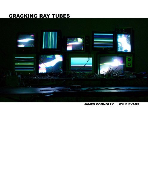
<strong>CRACKING</strong> <strong>RAY</strong> <strong>TUBES</strong><br />
JAMES CONNOLLY<br />
KYLE EVANS
<strong>Cracked</strong> <strong>Ray</strong> <strong>Tube</strong> is a collaborative realtime project that breaks and disrupts the interfaces of analog<br />
televisions and computer monitors to produce flashing, screeching, wobbulating, self-generated electronic<br />
noise and video.<br />
Our audio and video hacks for televisions and VGA computer monitors were first developed as independent<br />
projects, and collaboration grew out of their natural compatibility. With the computer monitors,<br />
the red, green, and blue video signals of the VGA cable are processed and fed back through<br />
a sound mixer simultaneously generating the audio and video information, which is received, deciphered<br />
and displayed by multiple computer monitors. On the other side, transmitted video is distorted<br />
through both physical contact with handmade circuitry and by electromagnetic flexing and folding of<br />
high powered electron beams within modified televisions. In both of our systems, the interfaces of<br />
the hardware are hacked, removed, and replaced with structures that function in a far less controlled<br />
and more chaotic manner, able to be manipulated through complex instrumentation resulting in unexpected<br />
outcomes that differ greatly from their intended use as commodities. Rather than using it to<br />
generate signals to be consumed by the viewer, we’re interested in examining the cathode ray tube<br />
as raw material in itself, as a physical object capable of breaking the viewer’s expectations of the<br />
familiar act of passively staring at television and computer screens. We’re interested in engaging with<br />
the methods developed by artists who have examined the cathode ray tube in its own aesthetic qualities<br />
including Ben Leposky’s Oscillons of the 1950s, the endless experiments of Nam June Paik, the<br />
Sandin Image Processor, as well as several artists currently working in the collaborative New Media<br />
art world, such as the Chicago group Arcanebolt.<br />
This document describes the way our system works through schematics and tutorials. It explains how<br />
to hack the communication networks of these hardwares in order to create new and alternative uses<br />
that differ from their intended purposes. This information is presented as a starting point from which<br />
your own methods of making, breaking, hacking, and restructuring can follow.<br />
James Connolly and Kyle Evans<br />
crackedraytube.com<br />
Copy-It-Right, 2011<br />
2
CONTENTS<br />
i. SYSTEM SCHEMATICS 6<br />
ii. HARDWARE HACKING TUTORIALS<br />
3. HACKING A VGA TO BEND AUDIO INTO VIDEO 8<br />
2. BUILDING A DIY VIDEO TRANSMITTER 17<br />
3. BUILDING A DIY ELECTROMAGNET 33<br />
4. HACKING A TELEVISION WITH A DIY ELECTROMAGNET 41<br />
Cover photo and photographs on pages 2 and 3 by Andy Rivera. Photographs on page 50 by Courtney<br />
Ziegler.<br />
3
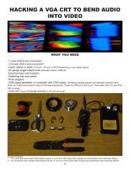
HACKING A VGA CRT TO BEND AUDIO<br />
INTO VIDEO<br />
WHAT YOU NEED<br />
-1 male VGA d-sub Connector 1<br />
-1 female VGA d-sub connector 2<br />
-Audio cables or jacks (1/4 inch, 1/8 inch, or RCA depending on your ideal output)<br />
-22-gauge single-strand wire (stranded makes it difficult)<br />
-Electrical tape and scissors<br />
-Soldering iron and solder<br />
-Wire strippers<br />
-VGA signal generator or computer with VGA output. (Sending unstable signals can damage computer hardware,<br />
so I highly recommend using a VGA signal generator. These are difficult to find, but it I have seen them for less than<br />
$20 on ebay.)<br />
-VGA CRT (tube) computer monitor (LCD will not work)<br />
1 You could also use a male VGA breakout board, or cut into a VGA cable itself, though wire-identification then becomes difficult<br />
2 You could also use a female VGA breakout board, or cut into a VGA cable itself, though wire-identification then becomes difficult<br />
8
UNDERSTANDING A VGA CABLE<br />
A computer monitor communicates through a Video<br />
Graphics Array (VGA) connector, which is organized<br />
into a 15 pin (3 rows of 5) adapter at either end that<br />
sends discrete (and, therefore, hackable) RGBHV<br />
(RED, GREEN, BLUE, HORIZONTAL-SYNC, VERTI-<br />
CAL-SYNC) analog signals.<br />
The most useful part of its organization is that the RED,<br />
GREEN, and BLUE (R, G, B) colors of the monitor are<br />
controlled by three discrete pins─pins 1-3. These are<br />
the pins the stereo audio signal gets sent to. Pin 13 is<br />
Horizontal-sync, which controls the frame rate and of<br />
the displayed image, and pin 14 is the Verical-sync,<br />
which displays the pixel information. Pin 5 is ground,<br />
and pins 6-10 are the ground connections for the R, G,<br />
B, H-SYNC, and V-SYNC.<br />
For this hack, wires need to be connection to pins 1 (R),<br />
2 (G), 3 (B), 5-10 (ground), 13 (horizontal-sync), and 14<br />
(vertical-sync)<br />
NOTE: D-sub connectors with soldering terminals are<br />
labeled with small numbers to ensure you’re soldering<br />
into the correct holes (this can get VERY confusing, as<br />
female soldering terminals are the opposite of male, and<br />
on top of that you’re seeing them in reverse). To save<br />
time and avoid having to resolder, be sure you’re placing<br />
the wire into the correct terminal BEFORE applying<br />
any solder.<br />
R G B<br />
GRND<br />
PIN 1:<br />
RED<br />
PIN 2:<br />
GREEN<br />
PIN 3:<br />
BLUE<br />
PIN 4: -<br />
PIN 5:<br />
GROUND<br />
PIN 6:<br />
RED GROUND<br />
PIN 7:<br />
GREEN GROUND<br />
PIN 8:<br />
BLUE GROUND<br />
PIN 9: -<br />
PIN 10:<br />
SYNC GROUND<br />
PIN 11: -<br />
PIN 12: -<br />
PIN 13:<br />
HORIZONTAL-SYNC<br />
PIN 14:<br />
VERTICAL SYNC<br />
PIN 15: -<br />
GRND B G R<br />
male face<br />
GRND<br />
H V<br />
B G R<br />
V H<br />
R G B<br />
male solder terminals<br />
GRND<br />
female face<br />
V H<br />
H V<br />
female solder terminals<br />
9
THE HACK<br />
1. SOLDERING THE D-SUB CONNECTOR<br />
This is the most difficult part of the hack. 15-pin d-sub connectors contain solder terminals to connect<br />
wires to 15 pins. For the purpose of this hack, only 10 of the 15 pins need to be soldered to.<br />
1.1 PREPARING<br />
-Cut 3 pieces of single-strand wire about 6 inches in length. Make sure that all pieces are as<br />
close to being the same length as possible.<br />
-Strip one end of each 6-inch piece of wire a quarter of an inch (this end will be soldered to the<br />
d-sub connector), and the other end half an inch (this will be soldered to the wire connected to<br />
the female d-sub connector.<br />
-These wires are for the R, G, and B pins of the male and female d-sub connectors separately.<br />
-Cut an additional 7 pieces of single-strand wire about 12 inches in length, making sure that all<br />
pieces are as close to being the same length as possible.<br />
-Strip both ends of each wire a quarter of an inch.<br />
-These wires will connect the ground pins and H and V sync pins on the male d-sub connector<br />
to the ground pins and H and V sync pins on the female d-sub connector.<br />
10
1.2 SOLDERING THE GROUND PINS IN THE MIDDLE ROW<br />
-Solder 4 separate pre-cut 12 inch wires to solder terminals 6, 7, 8, and 10 (note that pin 9 is not<br />
necessary to solder) of the male d-sub connector.<br />
male d-sub<br />
connector<br />
10 8 7 6<br />
hold solder to the<br />
solder terminal<br />
itself until it melts,<br />
then push it toward<br />
the soldering iron<br />
place soldering iron on<br />
the bare wire beyond<br />
solder terminal but<br />
away from the nonstripped<br />
plastic<br />
TIP: When soldering into the solder terminals, it works best to slide the wire into the terminal and<br />
then tape the wire to the table you’re working on to act as a “third hand”, holding it in place while<br />
you solder the wire.<br />
IMPORTANT: Make sure you solder the middle row of terminals (pins 6, 7, 8, and 10) before<br />
soldering the top and bottom row, or else it will be almost impossible to access those terminals<br />
with the soldering iron.<br />
male d-sub<br />
connector<br />
10 8 7 6<br />
11
-Solder the other end of those wires into the corresponding solder terminals 6, 7, 8, and 10 on<br />
the female d-sub connector.<br />
female d-sub<br />
connector<br />
6 7 8 10<br />
male d-sub<br />
connector<br />
female d-sub<br />
connector<br />
1.3 SOLDERING THE H AND V SYNC PINS<br />
-Solder 2 separate pre-cut 12 inch wires to solder terminals 13 and 14 of the male d-sub connector.<br />
-Solder the other end of those wires into the corresponding solder terminals 13 and 14 on the<br />
female d-sub connector.<br />
H V<br />
male d-sub<br />
connector<br />
female d-sub<br />
connector<br />
V H<br />
12
1.4 SOLDERING THE R, G, AND B PINS AND REMAINING GROUND PIN<br />
-Use the remaining pre-cut 12 inch wire to solder terminal 5 of the male pin to terminal 5 of the<br />
female pin, completing the ground connection.<br />
-Take the 3 pre-cut 6 inch wires. Solder the end that has been stripped to a quarter of an inch into<br />
solder terminals 1, 2, and 3 on the FEMALE d-sub connector (it is unessecary to solder them<br />
to the male d-sub connector).<br />
female d-sub<br />
connector<br />
1/R 2/B 3/G 5/GRND<br />
connect to the<br />
audio signal<br />
R, G, and B<br />
pins<br />
male d-sub<br />
connector<br />
female d-sub<br />
connector<br />
connects to<br />
the signal<br />
generator or<br />
computer<br />
connects to<br />
the monitor<br />
2. SENDING AUDIO SIGNALS TO THE R, G, AND B PINS<br />
To connect audio to the R, G, and B signals of a VGA cord in a way that shows all colors discretely the<br />
three cords have to be connected to the left channel, the right channel, and the ground of an audio signal.<br />
The pin connected to the ground signal generates the majority of the visuals, so I prefer to connect<br />
the RED pin. The left and right channels can be connected to the BLUE or the GREEN pins interchangably.<br />
This tutorial has you connecting the pins to two mono 1/4 inch jacks though, depending on your<br />
ideal output, you could also use 1/8 inch jacks or RCA jacks.<br />
13
2.1 UNDERSTANDING A 1/4 INCH AUDIO JACK<br />
-Mono 1/4 inch jacks make contact with the audio adapter at two points, one being the positive<br />
connection and the other the negative. Both points of contact have their own solder lugs.<br />
-The lug making contat with the tip of the adapter is the positive signal. The positive lug on one<br />
jack will be attached to 2 color pins.<br />
-The lug making contact with the base of the adapter is the negative signal. This lug on one of<br />
the jacks will be connected to the one of the color pins and will form the majority of the visuals.<br />
-Experiment with different combinations to see which you like best.<br />
lug attached to positive signal<br />
lug attached to negative signal<br />
1/4 inch jack one 1/4 inch jack two<br />
attach to R, G, or<br />
B pin<br />
attach to R, G, or<br />
B pin<br />
attach to R, G, or<br />
B pin (will generate<br />
the majority of the<br />
visuals.<br />
14
2.2 SOLDERING THE 1/4 INCH JACKS<br />
-Cut three 6-inch wires and strip both ends 3/4 of an inch on all.<br />
-Connect one end of 2 of the wires to each positive solder lug on both jacks by putting the wire<br />
half-way through the hole and twisting it to hold it in place, then solder them together.<br />
-Connect one end of the remaining wire to a negative solder lug on one of the two audio jacks<br />
the same way and solder them together.<br />
positive lugs,connect both to a color pin<br />
negative lug, connect one to a color pin to<br />
generate the majority of the visuals.<br />
2.2 CONNECTING THE 1/4 INCH JACKS TO THE R, G, AND B PINS<br />
-Solder the other end of the wire attached to the NEGTIVE lug of one of the audio jacks to one<br />
of the wires soldered to the color pins.<br />
-Solder the other ends of the wires attached to the POSITIVE lugs of each of the audio jacks to<br />
the 2 of the wires attached to color pins<br />
-(It doesn’t matter which pin goes to which lug, just make sure two are attached to each of the<br />
positive signals and one is attached to one of the negative signals).<br />
15
3. FINISHING UP<br />
-Wrap the connections of the audio cable to the R, G, and B pins with electric tape.<br />
-You may want to apply glue form a glue gun to the solder terminals of the male and femal d-sub<br />
connectors to keep the wires firmly in place, especially if you weren’t using shrink wrap tubing.<br />
-You may want to use zip ties or electric tape to keep the wires organized and together.<br />
Insert mono<br />
audio input<br />
Insert mono<br />
audio input<br />
female d-sub connector-<br />
attach to<br />
monitor<br />
female d-sub connector-<br />
attach to<br />
signal generator<br />
4. CONNECTING THE HACK<br />
-The female end of the hacked VGA cord connects to the VGA cord that goes to the VGA CRT<br />
computer monitor.<br />
-The male end of the hacked VGA cord needs to be stabilized by being connected to a VGA<br />
signal generator.<br />
-You could also add potentiometers to the connection between the audio and the color pins with<br />
switches to control the level of each signal.<br />
-Experiment with the setup. Add additional audio signals to the color pins. Connect multiple color<br />
pins to the same audio signal. Plug in a synthesizer or a function generator to have complete<br />
control of the visualized waveforms. Try to do more than just send a stable stream of audio into<br />
the monitor.<br />
IMPORTANT NOTE: You could stabalize the VGA signal through a computer or a VGA output<br />
from a laptop, but the hardware of the computer may be damaged after sending audio into the<br />
hacked VGA cord for prolonged periods of time. Because the audio is being sent to the ground of<br />
the VGA cable in order to have the red, green, and blue signal of the monitor discretely hacked, it<br />
is possible that raw voltage could be thrown back into the computer in a way that could damage<br />
the Hardware. Because of this, I highly recommend using a VGA signal generator.<br />
16
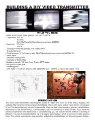
BUILDING A DIY VIDEO TRANSMITTER<br />
WHAT YOU NEED<br />
- Blank PCB Copper Plate (jameco.com part #169279)<br />
- Capacitors: 2x 0.1uf<br />
1x 100u<br />
2x 6-70pf Variable Caps (jameco.com part #32855)<br />
- Resistors: 27kOhm<br />
10kOh<br />
- Transistor-MPSA18 (jameco.com part #210681)<br />
- 1k potentiometer<br />
- Small amount (~4”) of magnet wire 24 AWG or close (jameco.com part #2098419)<br />
- Sand paper<br />
- Stranded hookup wire<br />
- Hacksaw or dremel tool<br />
-Headphones with 1/8” plug (from iPod or MP3 player)<br />
- Hot glue or super glue<br />
- Soldering Iron<br />
- CRT “tube” TV with an antenna (the transmitter won’t transmit to newer flat screen TV’s)<br />
INTRODUCTION<br />
This micro video transmitter was designed by the DIY radio and micro TV artist Tetsuo Kogawa. His<br />
website (http://anarchy.translocal.jp/) is full of great info on DIY radio, and all credit for this circuit goes<br />
to him.The transmitter can be used to transmit a relatively clear video signal or abstract visualizations,<br />
depending on the desired output. It will usually function at a distance of about 20 feet. If you have any<br />
previous experience with electronics or circuit building, you will notice that this method of building is<br />
different. The circuit is constructed on top of a copper “ground plate” which is common in radio applications.<br />
This tutorial uses step-by-step sketches and photos created based on Tetsuo Kogawa’s design.<br />
17
BUILDING THE TRANSMITTER<br />
1. PREPARING THE COPPER PLATE<br />
- Take the bare copper plate and cut off 1inch of material using a dremel tool or hacksaw.<br />
- Use this material to cut out 6 square ½ in. x ½ in. pieces.<br />
- Arrange the 6 pieces on the larger copper plate as shown in the image below…<br />
apply super glue to bottom of<br />
placed squares<br />
**NOTE** Be sure to arrange them so that all the component leads will be able to reach the<br />
squares. Look ahead to see what components will go where so you know exactly how to space<br />
them.<br />
- Once you have them arranged, put a dab of hot or super glue on the bottom of each square and<br />
stick them in place on the copper plate.<br />
18
2. ADDING THE 100uF CAPACITOR (the cylinder with “100uF” written on the side)<br />
- Melt a blob of solder onto the two squares furthest to the right. To do this, apply your iron to each<br />
square to transfer heat for an extended period of time until the solder flows onto the surface.<br />
apply blobs of solder<br />
reheat solder blobs and put the<br />
capacitor into place<br />
- Bend the legs out of the 100uf capacitor and straddle them between the two squares making<br />
sure that the leads are only touching the two small squares (not touching the ground plate).<br />
- Cut the excess off of the leads.<br />
- One at a time, re-heat the solder blobs and place the capacitor leads into them, allowing them<br />
to cool down until they stay in place.<br />
19
***NOTE*** - This capacitor is polarized meaning that it has to be facing in the appropriate direction.<br />
Make sure you solder the NEGATIVE lead to the LOWER of the two squares. The negative<br />
side has the shorter lead and a vertical stripe along the side of the capacitor.<br />
20
3. ADDING THE .1uF CAPACITORS (the two discs with “104” written on them)<br />
- These capacitors will be positioned between the upper and lower left most squares and the<br />
ground plate. Melt a blob of solder on these two squares and two blobs on the ground plate beside<br />
each. (Reference the pictures for exact positioning).<br />
- Re-heat the blobs and position the capacitors accordingly as in step 2.<br />
21
4. ADDING THE RESISTORS (10k and 27k)<br />
- Solder the 10k resistor (brown, black and orange stripes) between the bottom left square and<br />
ground.<br />
- Solder the 27k resistor (red, violate and orange stripes) between the two left squares.<br />
22
5. ADDING THE COIL<br />
- Cut about 4” of the magnet wire (24 AWG or close)<br />
- Use the plug from your headphones to wrap the wire around. Make 5 turns.<br />
- With the wire still wrapped around the headphone plug, take a small piece of sand paper<br />
and rub off the colored insulation of each end until the bare copper is exposed (If the copper<br />
is not exposed, you won’t be able to make a connection).<br />
- Solder the coil into place bridging the two squares as seen below<br />
23
6. ADDING THE VARIABLE CAPACITORS<br />
*NOTE* Once the component leads start to pile up on each other on each square, it helps to add<br />
additional solder.<br />
- The first variable capacitor will be soldered between the top square of the three that make up<br />
the bottom triangle and the ground plate.<br />
- Solder the “nose” of the capacitor (the lead that is different from the other two) to the square,<br />
and the other two side leads to the ground plate.<br />
*NOTE* You will have to bend the leads in a certain way in order to get everything positioned<br />
properly. Just play around with it till you get it.<br />
- The second variable capacitor will bridge between top and right squares of the triangle. Only<br />
two leads are needed here so use your clippers to remove one of the side leads, leaving the<br />
nose and only one side. (See the pic below)<br />
24
The variable capacitors soldered into place…<br />
25
7. ADDING THE TRANSISTOR (MPSA18)<br />
*NOTE* This transistor is sensitive to heat and can be destroyed by the heat from your iron. Be<br />
sure to follow the necessary precautions below. But don’t worry if you do kill one, they are only<br />
~$.10 a piece.<br />
- The three leads of the transistor all do specific things and must go to the appropriate places.<br />
Here is a pic of the orientation of this transistor…<br />
C=Collector B=Base E=Emitter<br />
flat edge<br />
C<br />
BE<br />
- Each lead from the transistor will be soldered to the three different squares that make up the<br />
triangle, so you will have to bend the leads accordingly.<br />
- The B lead (base) goes to the left square of the triangle, the C lead (collector) goes to the top<br />
square, and the E lead (emitter) goes to the right square, as in the image below.<br />
B<br />
flat edge<br />
C<br />
E<br />
- Before you solder the transistor in place, you need to have a “heat sink” attached to protect<br />
it. This will draw some of the heat from the transistor to something else. To do this, simply<br />
take an alligator clip and attach it to the lead you are soldering…<br />
26<br />
place alligator clip<br />
between soldering<br />
iron and transistor<br />
to act as a heat sink
- Solder each lead in place attaching the clip lead to each one before doing so.<br />
27
8. ADDING THE 1k POTENTIOMETER<br />
- Put a bit of super glue or hot glue on the bottom of the potentiometer and stick it to the upper<br />
right corner with the leads facing towards the left of the plate.<br />
- Take a small amount of stranded hookup wire and strip both ends. Solder one side to the upper<br />
most lead and the other side to the ground plate.<br />
- Repeat the process by connecting the middle lead of the potentiometer to the upper most of<br />
the two right squares. Then connect the lower lead of the potentiometer to the right most square<br />
of the triangle.<br />
28
9. ADDING THE INPUT WIRES<br />
- Cut two small lengths (~4-5”) of your stranded wire and strip both sides<br />
- Solder one of the wires to the ground plate (this will be the ground input from your video<br />
source)<br />
- Solder the other wire to the bottom square of the two right squares. (This will be the signal input<br />
from your video source)<br />
29
10. ADDING THE BATTERY INPUT WIRES<br />
- Just like the last step, cut two shot pieces of wire and strip both ends.<br />
- Solder one of the wires to the ground plate (this will be the negative input from your 9volt battery).<br />
- Solder the other wire to the upper left square (this will be the positive input from your 9volt battery).<br />
30
11. ADDING THE ANTENNA<br />
- Cut about 2 feet of wire and strip one end.<br />
- Solder the wire to the right most square of the triangle.<br />
31
OPERATING<br />
- Find a video source (DVD player, VHS player, iPod etc.) that has a composite video output.<br />
- Use an alligator clip lead to connect the ground from your video source to the ground input<br />
of the transmitter. Using another alligator clip lead, attach the signal output from your<br />
source to the signal input of the transmitter.<br />
- Use two more alligator clips to connect the positive and negative of a 9v battery to the<br />
positive and negative battery inputs of the transmitter.<br />
- Turn on a CRT “tube style” TV and tune it to channel 2 or 3.<br />
- Turn your potentiometer to somewhere around 50%<br />
- Using a small screwdriver, tune the upper most variable cap slowly until you see the TV<br />
make a flicker or change.<br />
- Tune the second variable capacitor until you start to see some strong signal coming through<br />
- Tune the potentiometer and the two variable capacitors until you get the imagery you wan<br />
Send any comments, questions or suggestions to yaktronix.online@gmail.com<br />
32
BUILDING A DIY ELECTROMAGNET<br />
FOR TELEVISION HACKING<br />
WHAT YOU NEED<br />
-3/8” diameter STEEL dowel rod (length depends on how many E-mags you want to make)<br />
-Steel works good, but it at least hast to be a ferrous (magnetic) metal.<br />
(If your not sure, bring a fridge magnet to the hardware store and see if it sticks to it. If it sticks,<br />
you know its ferrous.<br />
-Hand Drill<br />
-Hack saw<br />
-Wire clippers<br />
-Electrical Tape and Scissors<br />
-Small piece of sand paper<br />
-Patience and Dedication<br />
-Multi-meter (optional, but it helps to have one)<br />
-Insulated Magnet Wire (jameco.com part #2098419)<br />
24 AWG seems to work best<br />
(AWG=American Wire Gauge, standards for wire thickness)<br />
33
BUILDING THE ELECTROMAGNET<br />
1. Use your hack saw to cut off a ~4” length piece from your dowel rod.<br />
2. Fit the small rod into the chuck of your drill, as if it’s a drill bit.<br />
Note: You need as much of the rod as you can outside of the chuck so only put it<br />
in far enough so that it holds in place.<br />
3. With the magnet wire, tie a knot around the top of the rod leaving about a 4” tail of wire. Tie the knot<br />
about ½” from the top.<br />
4. Wrap electrical tape around the knot to secure it. Make sure both sides of the magnet wire are outside<br />
of the tape.<br />
step 3 step 4<br />
34
5. Hold the magnet wire taught to one side of the rod and slowly begin to spin the drill.<br />
-You can hold the wire however feels most comfortable and use whichever rotation direction for<br />
the drill you like, just be sure to keep it tight.<br />
-The wire will start to stack one on top of the other as you guide it into position. If you mess up,<br />
just reverse the drill direction and pull the wire off until you reach the point of your mistake.<br />
-This first layer is very important and will affect the winding of the following layers, so try to be<br />
as clean as possible. Also, the closer the windings are together, the more powerful the magnet<br />
will be.<br />
6. Continue winding the wire making sure that you hold it tight. Once you reach the bottom, the top of<br />
the cuck will force the winding in the opposite direction and do the same process all the way back up.<br />
35
7.Once you reach back to the top, hold the wire tight and wrap electrical tape around the whole length of<br />
the rod. Don’t cover up the very tip of the metal rod with tape, and be sure to leave ¼” to ½” exposed.<br />
36
8. Repeat this process a few more times. The more wire you wind will result in a more powerful magnet<br />
but greater overall resistance. I usually wind my mine until I reach 5 Ohms of resistance. A good<br />
rule of thumb is that each up and down wind = 1 Ohm. So going up and down about 5 times is usually<br />
sufficient. But anything around 4 – 8 Ohms is good. If none of this makes sense, don’t worry and just<br />
experiment.<br />
To test the resistance of your magnet so far, find a stopping point at one of the ends and tape down the<br />
wire. Take your sand paper and rub off the insulation on both ends of the wound wire. This removes the<br />
colored insulation and exposes the bare wire. Take your multi-meter and test the resistance between<br />
the two points. If it is sufficient then snip off your wire, but if it’s not, keep on winding.<br />
9. When your finished winding, tape up length of the rod one last time and snip off the remaining wire<br />
leaving a few inches for a tail. Remove the magnet from the drill chuck and turn it over. You may notice<br />
that the bottom side closest to the chuck is not very well secured. Place some tape around the bottom<br />
covering the exposure to secure it.<br />
37
The finished magnet should look something like this. Make sure everything is secure with tape, but be<br />
sure to leave the top and bottom ends of the metal rod exposed.<br />
10. To test out your magnet, first make sure you have sanded off the insulation on both sides of the<br />
wire. Use some clip leads or some wire to attach the + and – of a 9v battery to the two leads of magnet<br />
wire. It doesn’t matter which side goes to + or – at this point. (Changing that will switch the north and<br />
south polarity of the magnet).<br />
You should be able to pick up a few paper clips or bottle caps with just the 9v.<br />
38
For more power, use more electricity. Try hooking it up to a DC power supply. The increase in available<br />
amps will increase the power of the magnet dramatically. But it will also increase the heat it generates.<br />
Sometimes it can be hot to the tough so be careful.<br />
Here are some examples:<br />
Holding a<br />
½” drill bit at<br />
about 10V<br />
Holding a screwdriver<br />
at about 10V<br />
Holding its own weight against a metal plate at<br />
about 15V<br />
A lantern battery would also work much more efficiently than the 9v. If you’re comfortable you can also<br />
try a moderately powerful DC wall wart, but don’t play around with plugging stuff into the wall unless you<br />
are more experienced. Remember: Batteries can’t hurt you, but wall power can!<br />
39
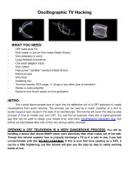
INTRODUCTORY INFORMATION ON USING AN ELECTROMAGNET FOR TELEVISION<br />
HACKING<br />
Though this will all be covered in the next tutorial, here is an explanation on where all this is going<br />
in regards to video hacking.<br />
If you have ever stuck a magnet on a CRT, you know how it alters the colors and images on the<br />
screen. Doing this internally makes for some very interesting and dramatic imagery.<br />
The electromagnet needs to be between 4 and 8 Ohms because this is around the same resistance<br />
of an audio speaker (or impedance when you’re talking about an alternating current signal like<br />
audio). If you amplify an audio signal, such as a sine wave, and replace the speaker with the magnet,<br />
you have a magnet that is rapidly switching polarity. This is useful over a stationary magnet because<br />
you can make an image wobble over time rather than just a still distortion. If none of this makes sense,<br />
don’t worry, it doesn’t have to in order to make it work. Here are some example results of the process:<br />
40
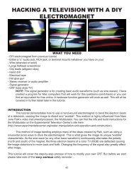
HACKING A TELEVISION WITH A DIY<br />
ELECTROMAGNET<br />
WHAT YOU NEED<br />
- DIY electromagnet from previous tutorial<br />
- Either a ¼” audio jack, RCA jack, or terminal mounts (whatever you have on you)<br />
- Wire (stranded or solid)<br />
- Large flathead screwdriver<br />
- Clip leads (alligator clips)<br />
- Hand drill<br />
- Electrical tape<br />
- Hot glue gun<br />
- Stereo receiver or audio amplifier<br />
- Signal generator<br />
- CRT (tube style TV)<br />
NOTE: The signal generator is for creating basic audio waveforms (such as sine waves). I have<br />
created a program for Mac computers that will work for this (yaktronix.com/tvhack) or you can<br />
find an equivalent for free online. A hardware function generator will work as well. This will all be<br />
covered in further detail later in the tutorial.<br />
INTRODUCTION<br />
This tutorial demonstrates how to use a hand-wound electromagnet to bend the electron beam<br />
of a television, causing the image to distort and “wobble”. This method is highly influenced from Nam<br />
June Paik’s video instrument/processor, the Wobbulator. You can find the info and build instructions for<br />
the Wobbulator on the Experimental Television Center’s site here:<br />
(http://www.experimentaltvcenter.org/raster-manipulation-unit-operation-and-construction).<br />
This method of image bending employs many of the ideas created by Paik, such as using a<br />
sinusoidal (sine) wave to drive the electromagnet. This is what gives the image its unique “wobble”<br />
characteristic. As the sine wave (or any other basic waveform) continuously alternates the polarity<br />
(north and south) of the magnet, the three electron beams of a color TV (RGB) are deflected causing<br />
the image distortions to move back and forth. Changing the frequency of the signal also greatly affectsthe<br />
image.<br />
This tutorial will cover the step-by-step process of how to modify your own CRT. But before we start<br />
please take note of this very serious safety reminder…<br />
41
OPENING A CRT TELEVISION IS A VERY DANGEROUS PROCESS. You will be<br />
handling a device that stores MANY times more electricity than what comes out of the<br />
wall. Though this tutorial explains how to properly discharge a TV so it is safe to use, if you<br />
feel uncomfortable with this DO NOT CONTINUE. If this is your first time opening up a CRT, it<br />
can be a little frightening, but this tutorial will give you the step by step to safely working inside<br />
of one.<br />
THE HACK<br />
1. FINDING THE RIGHT CRT AND OPENING IT UP<br />
It must be a CRT (tube style) TV, no flat screens will work for this. You can find these at all thrift<br />
stores around the world for dirt-cheap. Though almost any CRT will work, it does make a difference if<br />
you use a color or B+W TV. Using a color TV will result in the rainbow effect as the RG+B beams are<br />
deflected to the wrong points on the phosphorescent screen. A B+W TV will just give you the image<br />
distortions.<br />
When picking out your CRT, take into account the type of hardware holding it together and make<br />
sure you have the tools to open it. Also make sure that the screws are not challenging to get to. You can<br />
open up any TV, just some are more difficult than others.<br />
Before you open up the TV, make sure it is unplugged from the wall. Remove all the screws and<br />
set them aside. The big back part of the TV will be loose and can now be slid off. Sometimes older TV’s<br />
will have extra latches in the casing that you may have to use a screwdriver to detach. Be sure not to<br />
touch stuff in there until you really know what your doing. A CRT will hold a very powerful charge for a<br />
very long time. The TV is not safe to operate within until it has been properly discharged.<br />
2. DISCHARGING THE CRT<br />
*NOTE* It is important to follow basic electrical safety measures when dealing with high<br />
voltages. Where rubber sole shoes to keep yourself insulated and work on wood floors if available.<br />
Always keep one hand behind your back when discharging, as this will prevent the electricity<br />
from moving through your body from one hand to the other.<br />
For this step you will need to make a discharging tool using a big flathead screwdriver with an<br />
insulated handle (rubber or plastic) and a clip lead (alligator clip). Attach one side of the clip lead to the<br />
base of the metal of the screwdriver. The image below shows the tool I use to discharge TV’s that is attached<br />
to a clip lead that has been stripped on one side and wrapped around the screwdriver and held<br />
in place with heat shrink tubing.<br />
I would suggest using some electrical tape to make sure that the clip is secured to the screwdriver.<br />
42
Now attach the other end of the clip lead to the grounding wire or plate of the CRT. This will most<br />
likely be an exposed wire that runs around the outside of the tube. It looks like picture hanging wire. If<br />
that is not there then it is the metal frame surrounding the tube. The images below show the ground wire<br />
and how to attach the clip lead…<br />
43
Now locate the anode. The anode usually sits on the top of the tube and looks like a suction<br />
cup with a thick (usually red) wire coming out of it. With one hand behind your back and while wearing<br />
your rubber sole shoes, slide the screwdriver head underneath the rubber of the suction cup. There is a<br />
piece of metal underneath the cap that you want the screwdriver to make contact with. Once it touches<br />
it, you may hear a loud snap or a quick sizzle, but don’t worry because this is a good thing. That means<br />
the electricity is discharging. If you don’t hear a pop, don’t worry. Some CRT’s don’t hold as much of a<br />
charge so you may not hear it, but make sure the screwdriver is coming in contact with the metal under<br />
the rubber cap and that the clip lead is attached to the screwdriver and the ground wire.<br />
At this point, leave the screwdriver in place for a couple minutes to ensure that all the electricity<br />
has been discharged. After that, try discharging it one more time just to be safe. Now you have a safely<br />
discharged TV to work with.<br />
*NOTE* Even though the TV is safe to work with now, you should probably still stay away<br />
from the anode cup and the fly-back transformer that the red wire leads to. They are not used in<br />
the process and it’s best to be extra safe and just leave them alone.<br />
3. PLACING THE MAGNET<br />
In order to find the appropriate positioning to your liking, you<br />
will have to go through a process of temporarily securing the<br />
magnet in place then testing it out and repeating if necessary.<br />
Using Some electrical tape, strap the magnet to the<br />
area of the CRT shown in the picture below. I have found<br />
that the most responsive method of placing the magnet is<br />
by making sure one of the ends (poles) of the magnet is<br />
right next to the tube. There is less activity happening in the<br />
middle of the magnet so it is less responsive. But experimentation<br />
is key here.<br />
44
4. TESTING AND READJUSTING<br />
To test the magnet you will need to set up your stereo and a signal source. Your signal source can be<br />
anything really, but to get the most response out of the magnet some sources work better than others.<br />
Here are some things that work best…<br />
- Software I made for this at yaktronix.com/tvhack (Mac only)<br />
- Any other signal generator or test tone software (plenty of free ones out there. Google “free<br />
signal generator software”)<br />
- Test tone from your DAW like Logic or Pro Tools<br />
- Recordings of test tones played out of QuickTime, iTunes or an iPod<br />
- iPhone/Android app signal generator<br />
- Hardware function generator<br />
- Synthesizers (software of hardware)<br />
- Homemade synths (Ex. Nic Collins 7C14 square wave synth. Book: “Handmade Electronic Music”)<br />
*NOTE* The best range of frequency for magnet response is ~1Hz - ~300Hz. But experimentation is<br />
the best way to figure out what works best for you.<br />
45
The setup is as follows:<br />
- Plug your selected signal source into your stereo receiver’s input.<br />
- Connect speaker wire (or any wire) from the positive and negative terminals of one of the<br />
speaker outputs<br />
- Using clip leads, connect the two exposed wires of your magnet to the + and – of the speaker<br />
output. (This is the reason why, as said in the DIY magnet tutorial, the magnets should measure<br />
around 4-8 Ohms. This will trick the stereo into thinking the magnet is a speaker because speakers<br />
measure around the same impedance. It doesn’t have to be perfect to trick the stereo.)<br />
Make sure that no exposed wires are touching any parts of the insides of the TV. Cover all<br />
exposed wire in electrical tape.<br />
- Plug in a video source to your TV. It can be a DVD or VHS connected to the video input of the<br />
TV or, if it’s older, find one of the rare last remaining broadcast channels with some rabbit ears or<br />
build the DIY transmitter in the previous tutorial. Also, an FM modulator (Radio Shack) will convert<br />
a composite video signal from an RCA to a usable signal for an old TV with only an antenna<br />
input. If none of this, just use the static and find a video source later.<br />
- Plug in your TV and turn it on. Stay away from the inside when it’s on.<br />
- Make sure the volume to your stereo is turned down before you power on your signal source.<br />
This will be turned up gradually.<br />
- Turn on your signal source and tune it to around 60Hz. If your source is not tunable like this or<br />
if you have no idea what this means, just find a low to medium pitched sound. I would suggest<br />
starting with a sine tone and then experimenting with other waveforms after.<br />
- Turn up your stereo slowly until you start to see some reaction on the TV screen.<br />
SIGNAL SOURCE<br />
Computer software or<br />
hardware<br />
Speaker Out<br />
(+ and -)<br />
46<br />
MAGNET<br />
If you don’t see much happening, then try repositioning the magnetby following these steps:<br />
- Turn off the TV and unplug it<br />
- Discharge the TV again<br />
- Reposition the magnet and tape it down<br />
This part will take some experimentation on your part until you find the perfect positioning.<br />
If that is still not fixing the problem, here are some troubleshooting techniques…<br />
Test your magnet by removing it from the TV and hooking it up to the stereo independently. Double-check<br />
your stereo settings to make sure you have the proper inputs and outputs selected. Turn up<br />
the volume on the stereo with your signal source playing and place your screwdriver at the end of your<br />
magnet. It should vibrate the screwdriver at the frequency of your source signal. If you get no response<br />
out of it, it could be a problem with the stereo or your magnet.
5. FINISHING<br />
Once you have found the perfect positioning for the magnet, its time to install it permanently and create<br />
a way to “plug in” to your magnet from outside the TV after you close it up.<br />
- First, turn off, unplug and discharge your TV. Remember the location and positioning of the<br />
magnet and remove the tape holding it in place. Now hold the magnet positioned the way you<br />
want and apply large amounts of hot glue. Be generous with the glue and apply a few coats because<br />
the more you add, the sturdier it will be.<br />
- After the glue has dried, cut two lengths of wire (solid or stranded) ~2’ in length. Strip both ends<br />
and solder each wire to the two leads coming from your magnet. Wrap the connections with<br />
electrical tape when you’re done.<br />
*NOTE* – Do not leave any wires exposed. You want to be COMPLETELY ISOLATED from<br />
the internal electronics of the TV.<br />
47
- Find a location on the side of your TV that you can drill a hole to put your jack. 1/4” audio,<br />
RCA, terminal mounts or any connection will work for this. You just need a way to be able to<br />
plug into your magnet from the outside of the TV.<br />
- Drill a hole using the appropriate bit size for your selected jack and install it.<br />
- Solder the wires connected to your magnet to the two lugs of your jack.<br />
- Close up the TV and your ready to go.<br />
48
OPERATING<br />
Create the same setup as before with your signal source and stereo. The output of the stereo will have<br />
to match the input you chose to mount the TV so you will most likely have to cut up or create a cable<br />
for this. (Ex. Speaker wire from your stereo to a ¼” audio plug).<br />
Now you can experiment with using different video sources and signal sources to drive the magnet.<br />
Experiment with a range of frequencies or try using multiple sources at ounce. Check out yaktronix.<br />
com/tvhack to see how different frequencies affect the TV<br />
49
James Connolly (BFA With Emphasis in Art History, Theory, and Criticism, The School of the Art Institute<br />
of Chicago) is a sound, new media, and video artist, curator, and writer living in Chicago, Illinois.<br />
His work takes a critical relationship to digital culture through methods of appropriation, His work has<br />
been performed and shown at the 2009 SAIC Undergraduate Film Festival at the Gene Siskel Film<br />
Center, the Version Festival at the Co-Prosperity Sphere in Chicago, the Crtical Glitch Artware realtime<br />
event at NOTACON 2010, and the GLI.TC/H festival, among several other venues. He has been interviewed<br />
regarding his work and curatorial practices by blogs and periodicals including Bad At Sports and<br />
Furtherfield. He currently works as the Assistant Curator of the Roger Brown Study Collection of the<br />
School of the Art Institute of Chicago, and is co-organizer of the Strange Electronics series of realtime<br />
performances.<br />
Kyle Evans MFA, The School of the Art Institute of Chicago) is a sound designer, computer musician,<br />
electronic instrument creator, and realtime video performer. While his educational background<br />
was focused toward experimental music and sound art, his collective artistic work ranges from music<br />
technology development to multimedia installation. He has invented many electronic musical and video<br />
instruments ranging from studio-based synthesizers and performance-based computer interfaces to<br />
electronic modifications and augmentations to acoustic instruments. His performances and installations<br />
commonly explore the relation between modern and obsolete technologies, breaking and repurposing,<br />
and the dialogue between performer and technology. He has performed and presented his work<br />
throughout the United States including the 2010 International Computer Music Conference (ICMC) in<br />
New York, the Pixilerations New Media Showcase in Providence, the Guthman New Musical Instrument<br />
Competition 2010 in Atlanta and the 2011 Milwaukee Avenue Arts Festival in Chicago. His work has<br />
been presented in several publications including Popular Science Magazine and Hand Made Electronic<br />
Music by Nic Collins.<br />
Any questions and comments regarding the material in this document can be sent to jconno@saic.edu<br />
and kyleevans1123@gmail.com.<br />
crackedraytube.com<br />
jameshconnolly.com<br />
yaktronix.com<br />
50