CRACKING RAY TUBES - Cracked Ray Tube
CRACKING RAY TUBES - Cracked Ray Tube
CRACKING RAY TUBES - Cracked Ray Tube

You also want an ePaper? Increase the reach of your titles
YUMPU automatically turns print PDFs into web optimized ePapers that Google loves.
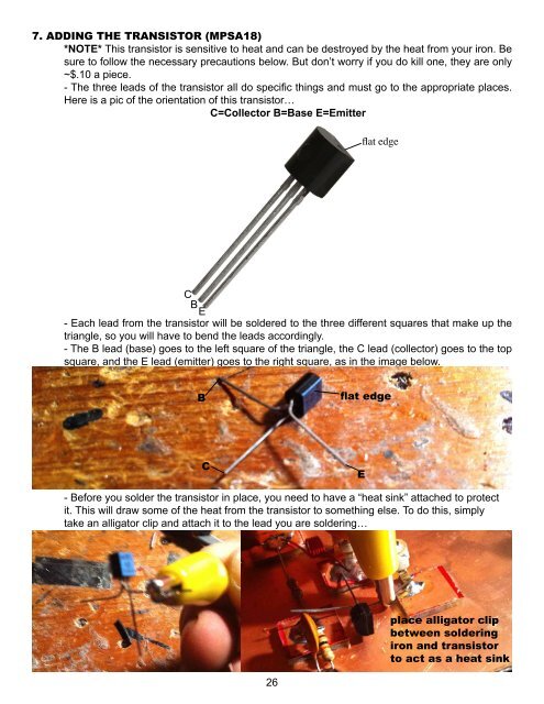
7. ADDING THE TRANSISTOR (MPSA18)<br />
*NOTE* This transistor is sensitive to heat and can be destroyed by the heat from your iron. Be<br />
sure to follow the necessary precautions below. But don’t worry if you do kill one, they are only<br />
~$.10 a piece.<br />
- The three leads of the transistor all do specific things and must go to the appropriate places.<br />
Here is a pic of the orientation of this transistor…<br />
C=Collector B=Base E=Emitter<br />
flat edge<br />
C<br />
BE<br />
- Each lead from the transistor will be soldered to the three different squares that make up the<br />
triangle, so you will have to bend the leads accordingly.<br />
- The B lead (base) goes to the left square of the triangle, the C lead (collector) goes to the top<br />
square, and the E lead (emitter) goes to the right square, as in the image below.<br />
B<br />
flat edge<br />
C<br />
E<br />
- Before you solder the transistor in place, you need to have a “heat sink” attached to protect<br />
it. This will draw some of the heat from the transistor to something else. To do this, simply<br />
take an alligator clip and attach it to the lead you are soldering…<br />
26<br />
place alligator clip<br />
between soldering<br />
iron and transistor<br />
to act as a heat sink