CRACKING RAY TUBES - Cracked Ray Tube
CRACKING RAY TUBES - Cracked Ray Tube
CRACKING RAY TUBES - Cracked Ray Tube

You also want an ePaper? Increase the reach of your titles
YUMPU automatically turns print PDFs into web optimized ePapers that Google loves.
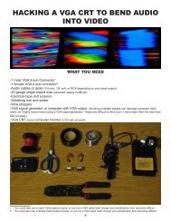
UNDERSTANDING A VGA CABLE<br />
A computer monitor communicates through a Video<br />
Graphics Array (VGA) connector, which is organized<br />
into a 15 pin (3 rows of 5) adapter at either end that<br />
sends discrete (and, therefore, hackable) RGBHV<br />
(RED, GREEN, BLUE, HORIZONTAL-SYNC, VERTI-<br />
CAL-SYNC) analog signals.<br />
The most useful part of its organization is that the RED,<br />
GREEN, and BLUE (R, G, B) colors of the monitor are<br />
controlled by three discrete pins─pins 1-3. These are<br />
the pins the stereo audio signal gets sent to. Pin 13 is<br />
Horizontal-sync, which controls the frame rate and of<br />
the displayed image, and pin 14 is the Verical-sync,<br />
which displays the pixel information. Pin 5 is ground,<br />
and pins 6-10 are the ground connections for the R, G,<br />
B, H-SYNC, and V-SYNC.<br />
For this hack, wires need to be connection to pins 1 (R),<br />
2 (G), 3 (B), 5-10 (ground), 13 (horizontal-sync), and 14<br />
(vertical-sync)<br />
NOTE: D-sub connectors with soldering terminals are<br />
labeled with small numbers to ensure you’re soldering<br />
into the correct holes (this can get VERY confusing, as<br />
female soldering terminals are the opposite of male, and<br />
on top of that you’re seeing them in reverse). To save<br />
time and avoid having to resolder, be sure you’re placing<br />
the wire into the correct terminal BEFORE applying<br />
any solder.<br />
R G B<br />
GRND<br />
PIN 1:<br />
RED<br />
PIN 2:<br />
GREEN<br />
PIN 3:<br />
BLUE<br />
PIN 4: -<br />
PIN 5:<br />
GROUND<br />
PIN 6:<br />
RED GROUND<br />
PIN 7:<br />
GREEN GROUND<br />
PIN 8:<br />
BLUE GROUND<br />
PIN 9: -<br />
PIN 10:<br />
SYNC GROUND<br />
PIN 11: -<br />
PIN 12: -<br />
PIN 13:<br />
HORIZONTAL-SYNC<br />
PIN 14:<br />
VERTICAL SYNC<br />
PIN 15: -<br />
GRND B G R<br />
male face<br />
GRND<br />
H V<br />
B G R<br />
V H<br />
R G B<br />
male solder terminals<br />
GRND<br />
female face<br />
V H<br />
H V<br />
female solder terminals<br />
9