Manual Técnico - Chiller YORK® Absorção YPC ... - Johnson Controls
Manual Técnico - Chiller YORK® Absorção YPC ... - Johnson Controls
Manual Técnico - Chiller YORK® Absorção YPC ... - Johnson Controls

Create successful ePaper yourself
Turn your PDF publications into a flip-book with our unique Google optimized e-Paper software.
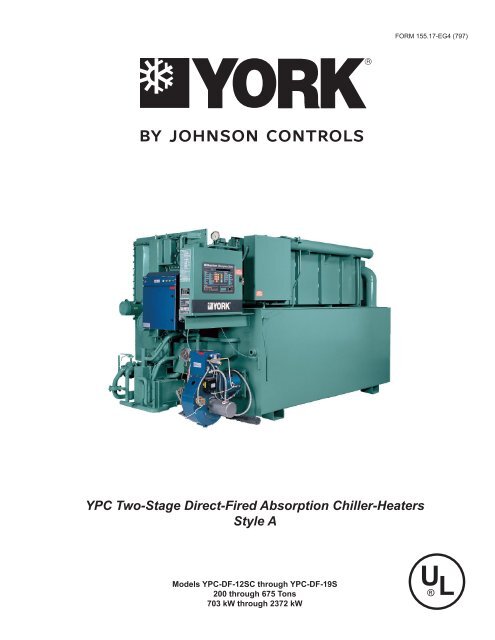
FORM 155.17-EG4 (797)<br />
<strong>YPC</strong> Two-Stage Direct-Fired Absorption <strong>Chiller</strong>-Heaters<br />
Style A<br />
Models <strong>YPC</strong>-DF-12SC through <strong>YPC</strong>-DF-19S<br />
200 through 675 Tons<br />
703 kW through 2372 kW
2<br />
YORK INTERNATIONAL
FORM 155.17-EG4<br />
TABLE OF CONTENTS<br />
How It Works............................................................................................................. 5<br />
Ratings...................................................................................................................... 9<br />
Control System ....................................................................................................... 10<br />
Mechanical Specifications ...................................................................................... 12<br />
Application Data ...................................................................................................... 16<br />
Dimensions ............................................................................................................. 25<br />
Electrical Data ........................................................................................................ 26<br />
Nozzle Arrangements ............................................................................................. 28<br />
Guide Specifications ............................................................................................... 30<br />
NOMENCLATURE<br />
The model number denotes the following characteristics of the unit:<br />
<strong>YPC</strong> - FN - 14SC - 46 - H-A<br />
Model<br />
Tube Code<br />
Heat Source<br />
Heater Code<br />
Size Code<br />
Electrical Code<br />
YORK INTERNATIONAL<br />
3
Millennium<br />
<strong>YPC</strong> Two-Stage Direct-Fired Absorption <strong>Chiller</strong>-Heaters<br />
200 to 700 Tons<br />
703 kW to 2372 kW<br />
TM<br />
27844A<br />
The YORK Millennium <strong>YPC</strong> Direct-Fired Absorption<br />
<strong>Chiller</strong> offers an environmentally-friendly alternative to<br />
electric energy. Since a <strong>YPC</strong> Direct-Fired <strong>Chiller</strong> uses<br />
inexpensive natural gas rather than electricity, owners<br />
can balance their energy needs and take advantage of<br />
the competition in an open energy market. And, because<br />
the unit also provides hot water for heating, typical applications<br />
will not require a boiler – saving even more<br />
money. With today’s energy and environmental considerations,<br />
the <strong>YPC</strong> Direct-Fired Absorption <strong>Chiller</strong> is the<br />
ideal choice for a wide range of applications.<br />
U.S. made <strong>YPC</strong> Direct-Fired <strong>Chiller</strong>s come equipped with<br />
the same sophisticated microprocessor controls found<br />
throughout YORK’s product lines, making the <strong>YPC</strong><br />
Direct-Fired <strong>Chiller</strong> the smartest absorber on today’s<br />
market.<br />
With its high efficiency, “smart controls,” proven reliability<br />
and the guaranteed quality of a standard performance<br />
test, U.S. made units are the ideal choice for today’s<br />
demanding specifications.<br />
4<br />
YORK INTERNATIONAL
How It Works<br />
FORM 155.17-EG4<br />
CHILLING CYCLE<br />
LD01609(R)<br />
CHILLING CYCLE<br />
<strong>YPC</strong>’s remarkably efficient two-stage absorption refrigeration<br />
cycle uses water as the refrigerant and lithium<br />
bromide as the absorbent. It is the strong affinity these<br />
two substances have for each other that makes the cycle<br />
work. The entire process occurs in hermetic vessels in<br />
an almost complete vacuum.<br />
The large diagram above indicates the complete chilling<br />
cycle. The six steps are detailed here and on the<br />
next page, with corresponding numbers in the diagram<br />
to show where each step takes place. <strong>YPC</strong>’s two-stage<br />
absorption chilling cycle is continuous; however, for the<br />
sake of clarity and simplicity, it is divided into six steps.<br />
1. Solution Pump/Heat Exchangers<br />
A dilute solution of lithium bromide and water descends<br />
from the Absorber to the Solution Pump. This flow of<br />
dilute solution is split into two streams and pumped<br />
through heat exchangers to the First-Stage Generator<br />
and to the Second-Stage Generator.<br />
<strong>YPC</strong>’s exclusive two-way split of solution flow virtually<br />
eliminates the possibility of crystallization (solidification)<br />
by allowing the unit to operate at much lower solution<br />
concentration and temperatures than series flow systems.<br />
Note: There are two heat exchangers, but only one is<br />
shown for illustrative purposes.<br />
2. First-Stage Generator<br />
A heat source heats dilute lithium bromide coming from<br />
the Solution Pump/Heat Exchangers. This produces<br />
hot refrigerant vapor which is sent to the Second-Stage<br />
YORK INTERNATIONAL<br />
5
How It Works<br />
Generator, leaving a concentrated solution that is returned<br />
to the Heat Exchangers.<br />
3. Second-Stage Generator<br />
The energy source for the production of refrigerant vapor<br />
in the Second-Stage Generator is the hot refrigerant<br />
vapor produced by the First-Stage Generator.<br />
This is the heart of YORK’s remarkably efficient<br />
two-stage absorption effect. The refrigerant vapor produced<br />
in the First-Stage Generator is increased by 40%<br />
– at no additional expense of fuel. The result is much<br />
higher efficiency than in conventional systems.<br />
This additional refrigerant vapor is produced when dilute<br />
solution from the Heat Exchanger is heated by refrigerant<br />
vapor from the First-Stage Generator. The additional<br />
concentrated solution that results is returned to<br />
the Heat Exchanger. The refrigerant vapor from the<br />
First-Stage Generator condenses into liquid giving up<br />
its heat, and continues to the Condenser.<br />
4. Condenser<br />
Refrigerant from two sources – (1) liquid resulting from<br />
the condensing of vapor produced in the First-Stage Generator<br />
and (2) vapor produced by the Second-Stage<br />
Generator – enters the Condenser. As the liquid refrigerant<br />
enters the low pressure of the condenser it flashes to<br />
vapor. The two sources of refrigerant vapor combine and<br />
condense to liquid as they are cooled by the condenser<br />
water. The liquid then flows down to the Evaporator.<br />
5. Evaporator<br />
Refrigerant liquid from the Condenser passes through<br />
a metering valve and flows down to the Refrigerant Pump,<br />
where it is pumped up to the top of the Evaporator. Here<br />
the liquid is sprayed out as a fine mist over the Evaporator<br />
tubes. Due to the extreme vacuum (6 mm Hg) in the<br />
Evaporator, some of the refrigerant liquid vaporizes, creating<br />
the refrigerant effect. (This vacuum is created by<br />
hydroscopic action – the strong affinity lithium bromide<br />
has for water – in the Absorber directly below.)<br />
The refrigerant effect cools the returning system chilled<br />
water in the Evaporator tubes. The refrigerant liquid/vapor<br />
picks up the heat of the returning chilled water, cooling<br />
it from 54°F to 44°F (12.2°C to 6.6°C). The chilled<br />
water is then supplied back to the system.<br />
6. Absorber<br />
As the refrigerant liquid/vapor descends to the Absorber<br />
from the Evaporator, a concentrated solution<br />
coming from the Heat Exchanger is sprayed out into<br />
the flow of descending refrigerant. The hydroscopic<br />
action between lithium bromide and water-and the related<br />
changes in concentration and temperature-result<br />
in the creation of an extreme vacuum in the Evaporator<br />
directly above. The dissolving of the lithium bromide<br />
in water gives off heat, which is removed by condenser<br />
water entering from the cooling tower at 85°F<br />
(29.4°C) and leaving for the Condenser at 92°F<br />
(33.3°C). The resultant dilute lithium bromide solution<br />
collects in the bottom of the Absorber, where it flows<br />
down to the Solution Pump.<br />
The chilling cycle is now completed and begins again<br />
at Step 1.<br />
6<br />
YORK INTERNATIONAL
FORM 155.17-EG4<br />
HEATING CYCLE WITHOUT HOT WATER HEAT EXCHANGER<br />
LD01610(R)<br />
HEATING CYCLE WITHOUT HOT WATER HEAT<br />
EXCHANGER<br />
1. First-Stage Generator<br />
An energy source heats dilute lithium bromide solution<br />
in the First-Stage generator. This produces hot refrigerant<br />
vapor which travels through the open valve VD and<br />
also moves through the Second-Stage generator and<br />
Condenser to the evaporator.<br />
2. Evaporator<br />
The hot refrigerant vapor travels through the evaporator<br />
where it gives up heat to the system hot water, and<br />
changes state from vapor to liquid as its heat is removed.<br />
The refrigerant liquid collects in the bottom of the evaporator.<br />
3. Refrigerant Pump<br />
The refrigerant pump removes the refrigerant liquid from<br />
the evaporator and pumps it into the second stage generator<br />
where it mixes with intermediate lithium bromide<br />
solution to form dilute lithium bromide solution.<br />
4. Heat Exchangers/Absorber<br />
The dilute lithium bromide flows to the solution heat<br />
exchanger where it combines with the concentrated<br />
solution from the First Stage generator to form intermediate<br />
solution. The intermediate solution then flows<br />
through the absorber.<br />
5. Solution Pump/Heat Exchangers<br />
The solution pump moves the intermediate solution from<br />
the absorber through the solution heat exchangers and<br />
into the first and second stage generators and the process<br />
begins again.<br />
YORK INTERNATIONAL<br />
7
How It Works<br />
HEATING CYCLE WITH OPTIONAL HOT WATER HEAT EXCHANGER<br />
LD01611<br />
HEATING CYCLE WITH OPTIONAL HOT WATER<br />
HEAT EXCHANGER<br />
1. First-Stage Generator<br />
Dilute lithium bromide solution is heated by the energy<br />
source in the First-Stage Generator. This drives off refrigerant<br />
vapor and leaves concentrated solution.<br />
2. Hot Water Heat Exchanger<br />
The hot refrigerant vapor from the first stage generator<br />
gives up its heat to the System Hot Water Heat Exchanger<br />
and condenses to liquid as the heat is removed.<br />
The condensed refrigerant liquid returns to the<br />
First-Stage Generator and the cycle begins again.<br />
8<br />
YORK INTERNATIONAL
Ratings<br />
FORM 155.17-EG4<br />
COMPUTERIZED PERFORMANCE RATINGS<br />
Each chiller selection is custom-matched to meet the<br />
individual application requirements. It is not practical to<br />
provide tabulated information for all possible combinations.<br />
Computerized performance ratings are available<br />
through each YORK Sales Office.<br />
Fig. 1 details the high efficiency part load performance<br />
of the <strong>YPC</strong> Absorption <strong>Chiller</strong>. At both constant tower<br />
water temperatures and ARI adjusted entering tower<br />
temperatures, the unique Millennium design delivers superior<br />
economy at low loads.<br />
FIG. 1 – ENERGY INPUT VS. OUTPUT*<br />
LD01612<br />
* Shows the part load performance of the YORK <strong>YPC</strong> chiller-heater. The highest efficiency is achieved between 50 and 100 percent chilling<br />
capacity. Valid for leaving chilled water temperature 42°- 52°F (6.6°C - 12.2°C).<br />
FIG. 2 – IPLV ANALYSIS**<br />
WEIGHTING<br />
ENTERING COND.<br />
FACTOR WEIGHTED<br />
LOAD (%) WATER TEMP. COP<br />
(FROM ARI AVERAGE COP<br />
°F °C 560-92)<br />
100 85.00 29.44 1.0 0.17 0.170<br />
75 78.75 25.97 1.097 0.39 0.428<br />
50 72.50 22.64 1.167 0.33 0.385<br />
25 68.00 20.00 1.089 0.11 0.120<br />
** IPLV (expressed as a COP) = 1.10<br />
YORK INTERNATIONAL<br />
9
Control System<br />
The YORK Millennium Control Center is designed for<br />
the very best in chiller protection and overall system<br />
efficiency. As standard equipment on all Millennium chillers,<br />
the Millennium Control Center is a major development<br />
in absorption chiller technology, providing the most<br />
precise and reliable control available in the industry.<br />
Information Display<br />
Vital chiller operating information can be shown on the<br />
40 character alphanumeric display. All information is in<br />
the English language with numeric data provided in<br />
English or metric units. Information provided standard<br />
on all units includes:<br />
• Chilled water temperatures, entering and leaving<br />
• Hot water temperatures, entering and leaving<br />
• Tower water temperatures, entering and leaving<br />
• First-stage generator pressure and temperature<br />
• Refrigerant temperature<br />
• Solution temperature<br />
• Operating hours<br />
• Number of starts<br />
• Number of purge cycles (last 7 days and lifetime total)<br />
• Burner firing rate command (in %)<br />
• Indication of each pump’s operation<br />
The operating program is stored in non-volatile memory<br />
(EPROM) to eliminate chiller failure due to AC power<br />
failure/battery discharge. In addition, programmed<br />
setpoints are retained in lithium battery-backed RTC<br />
memory for a minimum of 5 years.<br />
In addition, all operating and setpoint information can<br />
be transmitted to an optional remote printer through the<br />
RS-232 port to obtain data logs:<br />
• At any time by pressing the PRINT button<br />
• At set time intervals by programming the panel<br />
28342A (D)<br />
• After a safety shutdown to list the cause of the shutdown<br />
and the operational parameters just prior to<br />
shutdown<br />
• For a complete history print-out of the last four shutdowns<br />
and operational parameters just prior to<br />
shutdown<br />
Capacity Control<br />
When automatic capacity control is desired, the ISN<br />
Control Center automatically varies the burner firing rate<br />
to maintain the programmed leaving chilled water or hot<br />
water setpoint for cooling or heating loads ranging from<br />
30% to 100% of design. Features include:<br />
• Digital keypad entry of setpoint to 0.1°F (0.1°C)<br />
• Verify actual vs. setpoint temperature via alphanumeric<br />
display.<br />
• Remote reset of setpoint (up to 20°F (11.1°C)<br />
range) with a 1 to 11 second PWM signal (optional<br />
4-20 mA, 0-10VDC or contact closure).<br />
When automatic control is not desired, the input<br />
burner firing rate is also manually adjustable from<br />
the Millennium Control Center panel to any setting<br />
between minimum and maximum, provided heat input<br />
is not limited due to a specific operating condition<br />
(e.g. safety).<br />
System Cycling <strong>Controls</strong><br />
• Programmable seven-day time clock for automatic<br />
start/stop of chiller and chilled, condenser and hot<br />
water pumps.<br />
• Separate schedule input strictly for holidays<br />
• Remote cycling contacts available for other field<br />
supplied signals<br />
• Multi-unit cycling contact input terminals for field<br />
supplied signals<br />
10<br />
YORK INTERNATIONAL
FORM 155.17-EG4<br />
Warning Conditions/lnhibited Unit Loading<br />
The Millennium Control Center provides a warning display<br />
message and, when beneficial to the machine, will<br />
limit heat input to 30% or 60% when operating conditions<br />
indicate the unit is moving towards a safety shutdown.<br />
This gives the operator the opportunity to fix a<br />
problem before it leads to a complete safety shutdown.<br />
Warnings include the following:<br />
• Low refrigerant temperature<br />
• High generator pressure or temperature<br />
• High or low entering condenser water temperature<br />
• Purge pump current overload<br />
• Faulty solution dilution temperature sensor<br />
Shutdown <strong>Controls</strong><br />
The following conditions will lead to unit shutdown. After<br />
a shutdown, the reason for the shutdown is displayed<br />
in English on the alphanumeric display. Each annunciation<br />
details the day, time, reason for shutdown and the<br />
type of restart required.<br />
Cycling – those controls which automatically reset and<br />
permit auto restart of the system.<br />
• Loss of condenser water flow<br />
• Low leaving chilled water temperature<br />
• Power failure (when automatic restart is selected)<br />
Safety – those controls which (when employed) require<br />
a manual operation to restart the system.<br />
• Solution pump thermal or current overload<br />
• Refrigerant pump thermal or current overload<br />
• Low refrigerant temperature<br />
• First stage generator high temperature or pressure<br />
• First stage generator low solution level<br />
• Burner alarm indication<br />
• Burner Panel malfunction (combustion-related malfunction)<br />
• Loss of chilled water flow<br />
• Power failure (when automatic restart not used)<br />
• Incomplete dilution cycle due to any of the following:<br />
• Power failure<br />
• Solution/refrigerant pump overloads<br />
• Low refrigerant temperature<br />
• Loss of chilled water flow<br />
• Auxiliary safety shutdown terminals for field supplied<br />
signals<br />
Concentration Calculator<br />
The micropanel monitors the first-stage generator concentration<br />
to prevent operation at an unsafe concentration.<br />
Concentration is tied into both the Warning Conditions and<br />
Safety Shutdown systems discussed in this section. Also<br />
YORK INTERNATIONAL<br />
included is an operator interface concentration calculator.<br />
When in the Program mode, an operator can use the concentration<br />
calculator to determine concentration by inputting<br />
set of conditions. The operator must input any two of<br />
three parameters (bromide solution temperature, saturation<br />
temperature, and pressure) and the micropanel will<br />
display the concentration. The display will also indicate if<br />
the input conditions are in the crystallization zone.<br />
Control Mode Selection<br />
The Millennium Control Center includes secure programming<br />
and servicing capabilities. There are three<br />
keys for the selection of the control center modes:<br />
• ACCESS CODE permits access to the control center<br />
PROGRAM button when the proper password<br />
is given<br />
• PROGRAM permits operator to program the<br />
setpoints and select desired MODE:<br />
• LOCAL allows manual unit start and purging.<br />
• REMOTE allows remote start and stop of the<br />
unit remote reset of the chilled water temperature<br />
limit, while still allowing manual purging at<br />
the chiller.<br />
• SERVICE allows manual operation of the burner<br />
firing rate, including LOAD, UNLOAD, HOLD, and<br />
AUTO keys. <strong>Manual</strong> operation of all pumps is<br />
also included.<br />
Energy Management Interface<br />
By connecting with the YORK Integrated Systems Network,<br />
the Millennium Control Center can communicate<br />
all data accessible from the keypad (including all temperatures,<br />
pressures, alarms and operating data) to a<br />
remote DDC processor through a single shielded cable.<br />
In remote mode, the DDC processor may issue all operating<br />
commands available at the keypad to the control<br />
center through the same shielded cable. With an<br />
ISN translator panel, other BAS systems can receive<br />
this same information.<br />
The Millennium Control Center also provides a direct<br />
hard wire interface capability with other building automation<br />
systems using a 1-11 PWM standard signal (4-20<br />
mA, 0-10VDC or contact closure optional) including the<br />
following:<br />
• Remote unit start/stop<br />
• Remote chilled water temperature reset<br />
• Remote hot water temperature reset<br />
• Remote read out of status including:<br />
• Unit ready to start<br />
• Unit operating<br />
• Unit safety shutdown<br />
• Unit cycling shutdown<br />
11
Mechanical Specifications<br />
General<br />
The YORK Millennium <strong>YPC</strong> Direct-Fired Absorption Liquid<br />
<strong>Chiller</strong>-Heater is completely factory-packaged, including<br />
a first-stage (high temperature) generator,<br />
burner, burner panel, solution heat exchangers, main<br />
shell, hot water heater, microprocessor controls and all<br />
interconnecting unit piping and wiring.<br />
All models are shipped as a single piece complete with<br />
al factory balanced LiBr and refrigerant charge inside<br />
of the unit to simplify and expedite start up. The unit is<br />
also shipped with a nitrogen charge to eliminate the<br />
possibility of air entering the machine during shipment.<br />
Burner and Burner panel on each unit are factory<br />
mounted, wired and tested and ship preinstalled as integral<br />
components of the <strong>Chiller</strong>-Heater.<br />
The purchase price includes the services of a YORK<br />
factory-trained, field service representative to supervise<br />
the initial start-up of the machine.<br />
Solution Flow<br />
The solution flow is divided into two parallel paths, one<br />
leading to the first stage generator and one to the second<br />
stage generator. In this way, each stream is concentrated<br />
only once, allowing for a more safe and efficient<br />
operation. The balance of flow between the two streams<br />
is pre-set at the factory and fine-tuned at start up to ensure<br />
maximum efficiency for any given application.<br />
Main Shell<br />
The main shell consists of four separate shell and tube<br />
heat exchangers – the absorber, evaporator, condenser<br />
and second stage (low temperature) generator – all<br />
housed in a single carbon steel shell divided into low<br />
pressure and intermediate pressure sections. The shell<br />
is fabricated from formed carbon steel plates with fusion<br />
welded seams. Carbon steel tube sheets, drilled<br />
and reamed to accommodate the tubes, are welded to<br />
the end of the shell. Intermediate tube supports are fabricated<br />
of carbon steel plates. Each tube is roller expanded<br />
into the tube sheets to provide a leak tight seal;<br />
each tube is individually replaceable. The solution side<br />
of the shell is designed for a working pressure of 60<br />
mm Hg absolute.<br />
The portion of the shell opposite the burner houses the<br />
low pressure section of the machine which includes the<br />
evaporator and the absorber. Both the absorber and the<br />
evaporator are drip-type heat exchangers with 5/8"<br />
(15.875 mm) OD, .025" (0.635 mm) wall copper tubing<br />
for the 12SC-14SC, and 3/4" (19.05 mm) OD, 0.028"<br />
(0.71 mm) wall for the 15SL and larger. Tubes are externally<br />
enhanced where necessary to achieve desired<br />
capacity. The absorber and evaporator are separated<br />
by finned eliminator baffles designed to allow water in<br />
the vapor state to pass to the absorber.<br />
12<br />
The burner side of the shell contains the intermediate<br />
pressure section of the machine consisting of the condenser<br />
and second stage generator. The second stage<br />
generator is a drip-type heat exchanger with 5/8" (15.9<br />
mm), .025" (0.635 mm) wall, copper tubing for the<br />
12SC-14SC, and 3/4" (19.05 mm) OD, .028" (0.71 mm)<br />
wall for the 15SL and larger. Generator and condenser<br />
are separated by baffling which prevents liquid carryover<br />
to the condenser. Condenser tubing is 5/8" (15.875 mm),<br />
.025" (0.635 mm) wall copper tubing for the 12SC-14SC,<br />
and 3/4" (19.05 mm) OD, .028" (0.71 mm) wall for the<br />
15SL and larger.<br />
The removable compact water boxes are fabricated of steel.<br />
The design working pressure is 150 PSIG (1 MPa) and<br />
the boxes are tested at 225 PSIG (1.6 MPa). Integral steel<br />
water baffles are located and welded within the water box<br />
to provide the required pass arrangements. Stub-out water<br />
nozzles connections with Victaulic grooves are welded<br />
to the water boxes. These nozzles are suitable for Victaulic<br />
couplings, welding or flanges, and are capped for shipment.<br />
Plugged vent and drain connections and lifting lugs<br />
are provided on each water box.<br />
First Stage Generator<br />
The first stage generator is a single flooded heat exchanger<br />
using vertical carbon steel boiler tubes. The<br />
shell side is fabricated from carbon steel plate with fusion<br />
welded seams, and is designed for a working pressure<br />
of 13.5 PSIA (93 kPa). The unit bursting disk is<br />
designed to fail at 12 PSIG (83 kPa). Carbon steel eliminator<br />
baffles prevent solution carryover over with the<br />
refrigerant vapor. The generator uses a series of bare<br />
and enhanced vertically-oriented, carbon-steel boiler<br />
tubes to enhance heat transfer. Hot combustion gases<br />
flow from the combustion chamber across the tubes to<br />
provide the necessary heat input.<br />
The high temperature generator contains a solution float<br />
valve which controls the level of solution in the generator.<br />
This limits the amount of sensible heating at part<br />
load conditions, resulting in much better performance.<br />
Solution Heat Exchanger<br />
The solution heat exchanger is a shell and tube design<br />
with geometrically-enhanced 5/8" (15.875 mm) OD for<br />
the 12SC-14SC, and 0.578" (14.68 mm) OD for the 15SL<br />
and larger, 90/10 cupronickel tubing. The shell is formed<br />
from carbon steel plate with fusion welded seam. Tubes<br />
are roller expanded into carbon steel tube sheets.<br />
Burner<br />
The burner is a forced draft, flame retention burner listed<br />
by Underwriters Laboratories (IRI, FM and other codes<br />
available as options) and capable of operating on natural<br />
gas, propane, or No. 2 oil (as specified by the customer).<br />
YORK INTERNATIONAL
FORM 155.17-EG4<br />
The burner is made of welded steel and the combusion<br />
head incorporates a multi-blade stainless steel, flame<br />
retention diffuser. Minimum turndown ratio is 3 to 1.<br />
Combustion air is supplied by an integrally-mounted<br />
blower assembly incorporating a direct-drive, 3-phase<br />
motor. The burner uses a full-modulation-type fuel/air<br />
control system.<br />
The gas control train is prepiped and prewired with suitable<br />
junction boxes and terminal strips to burner panel<br />
terminal connections. The gas train contains the following<br />
components: manual shutoff cock, main gas pressure<br />
regulator, low and high gas pressure switches, two<br />
(2) UL listed leak test cocks, burner manifold gas pressure<br />
gauge, two (2) main motorized gas valves (for gas<br />
inputs of 5.0 MMBTU/HR and lower), two (2) main motorized<br />
gas valves – one (1) with proof of closure interlock<br />
switch (for gas inputs above 5.0 MMBTU/HR), and<br />
one (1) normally open vent valve sized according to IRI<br />
requirements.<br />
The oil control train (when specified) incorporates U.L.<br />
approved components supplied by the burner manufacturer<br />
to provide the specified fuel/air control operation.<br />
The system uses a single high pressure oil nozzle<br />
of the internal-bypass type. The nozzle oil train includes<br />
one (1) 300# (2.1 MPa) gauge to read nozzle return oil<br />
pressures.<br />
The high pressure nozzle supply oil pump is a two (2)<br />
gear type capable of producing 300 PSIG (2.1 MPa) discharge<br />
pressure and 15 inches (381 mm) Hg. vacuum. It<br />
is a separate unit mounted on its own support base with a<br />
direct drive motor. The oil pump unit comes complete with<br />
removable mesh-type oil strainer, 0-300 PSIG (2.1 MPa)<br />
oil nozzle pressure gauge, nozzle line, main and auxiliary<br />
solenoid safety shutoff oil valves and low oil pressure<br />
switch. The oil nozzle bypass line uses dual check valves.<br />
The flame safeguard control includes fully automatic<br />
prepurge and post-purge sequencing of the burner blower<br />
motor, interrupted ignition system, and fuel/air flow components<br />
with an ultra violet sensor for flame detection.<br />
Pumps<br />
Solution and refrigerant pumps are hermetically sealed,<br />
self-lubricating, totally enclosed, liquid cooled,<br />
factory-mounted, wired and tested. Motor windings are not<br />
exposed to LiBr or water. The suction and discharge connections<br />
for each pump are fully welded to the unit piping<br />
to minimize the opportunity for leaks. Suction and discharge<br />
connections are also equipped with factory installed isolation<br />
valves to permit quick and easy servicing of pumps.<br />
AII <strong>YPC</strong> units include one or two solution pump(s) and a<br />
refrigerant pump. Pumps are designed to operate for a<br />
total of 55,000 hours between service inspections.<br />
Valves<br />
All valves used for adjusting the solution are fully welded<br />
or brazed to prevent leakage of air into the unit. Valve<br />
actuators are covered with a seal cap to eliminate the<br />
possibility of air leakage through the stem. Additionally,<br />
all connections of valves to unit piping are fully welded.<br />
Solution and Refrigerant<br />
Each Millennium unit is charged with lithium bromide<br />
solution with non-toxic lithium molybdate as a corrosion<br />
inhibitor. Refrigerant is deionized water. A small amount<br />
of 2-ethyl hexanol is added as a heat and mass transfer<br />
enhancer.<br />
Purge System<br />
The purge system automatically and constantly removes<br />
noncondensible vapors generated in the absorption process<br />
through the use of an eductor. Noncondensibles<br />
are then stored in a purge chamber until they can be<br />
removed through the use of a purge pump. The purge<br />
pump is an oil, rotary, two-stage vacuum pump with a<br />
1/4 HP, 3-Phase, ODP motor.<br />
The chiller control panel includes a SmartPurge system<br />
that will automatically sense the amount of noncondensibles<br />
in the purge chamber and empty the tank<br />
whenever necessary. The SmartPurge system eliminates<br />
the need for an operator to ever manually empty the purge<br />
chamber. In addition, the control panel monitors the frequency<br />
of purge cycles and alerts the chiller operator,<br />
through a unique control panel warning message, if the<br />
number if purges exceeds normal levels.<br />
Capacity Control<br />
Capacity control is accomplished by modulating the<br />
burner’s firing rate. The <strong>YPC</strong> Direct-Fired unit is capable<br />
of modulating capacity from 30% to 100%.<br />
The two-stage chiller design incorporates a float valve<br />
that limits solution flow to the generator as the cooling<br />
load decreases. This maintains optimum solution level<br />
throughout the operating range. In addition, manual control<br />
valves are used by YORK technicians in the factory<br />
and/or at start-up to fine tune solution and refrigerant<br />
flows to match the jobsite needs at peak efficiency.<br />
Power Panel<br />
The power panel enclosure includes the following: single<br />
point wiring connection for the incoming power supply;<br />
non-fused disconnect switch; motor starters, complete<br />
with current and thermal-overload protection for solution<br />
pump(s), refrigerant pump, and purge pump (current<br />
overloads only); 115VAC 50/60 Hz control power<br />
transformer.<br />
YORK INTERNATIONAL<br />
13
Mechanical Specifications<br />
Millennium Control Center<br />
The microprocessor based control center is<br />
factory-mounted, wired and tested. The electronic panel<br />
automatically controls the operation of the unit in meeting<br />
system cooling or heating requirements while minimizing<br />
energy usage. <strong>Chiller</strong> operating parameters are<br />
sensed by either thermistors or transducers and displayed<br />
on the keypad. All pressures are taken as absolute<br />
to alleviate typical gauge pressure inaccuracies.<br />
Temperatures and pressures can be displayed in English<br />
(F, PSIA) or metric (C, KPa) units depending on<br />
the application. Display of all information is shown in<br />
the English language on a 40-character alphanumeric<br />
display.<br />
Available operating information includes return/leaving<br />
chilled water temperatures, return/leaving tower water temperatures,<br />
first stage generator pressure and temperature,<br />
refrigerant and solution temperatures, operating hours,<br />
burner firing rate and number of starts and purges.<br />
Warning Conditions – The Millennium Control Center<br />
provides a warning annunciation and, when appropriate,<br />
limits heat input under the following conditions:<br />
low refrigerant temperature, high generator pressure or<br />
temperature, high or low entering condenser water temperature,<br />
purge pump current overload, faulty solution<br />
dilution temperature sensor.<br />
Safety <strong>Controls</strong> – The control center includes unique<br />
safety logic designed to protect the <strong>YPC</strong> chiller from damaging<br />
malfunctions. Complete safety annunciation is displayed<br />
for each shut-down by pressing the status key. This<br />
information includes day, time and reason for shutdown.<br />
These include: solution- or refrigerant-pump thermal or<br />
current overload, low refrigerant temperature, first-stage<br />
generator high pressure or temperature, loss of chilled<br />
water flow, power failure, burner safety shutdown, auxiliary<br />
safety shutdown, incomplete dilution cycle and power<br />
failure if manual restart after power failure is selected.<br />
Operating <strong>Controls</strong> – Background messages are displayed<br />
while the unit is running to signal operator of<br />
controlling conditions such as leaving chilled water temperature<br />
control and non-critical sensor error. System<br />
cycling messages display day, time, cause of cycling<br />
shutdown, and autostart indication. These include loss<br />
of condenser water (or hot water) flow, low-leaving<br />
chilled water (or high leaving hot water) temperature,<br />
and power failure (when autostart is selected).<br />
Digital programming of operating setpoints from the<br />
keypad include leaving chilled water (or hot water) temperature,<br />
pulldown demand limiting, remote reset temperature<br />
range daily start/stop scheduling of chiller and<br />
water pumps with separate holiday schedule.<br />
Security access code is provided for operator to program<br />
setpoints or to choose local, remote, or service<br />
modes of operation. <strong>Manual</strong> control of the burner firing<br />
rate and all pumps is provided through separate buttons<br />
in the service mode of operation.<br />
Data Logging – All operating and setpoint information<br />
can be transmitted to a remote printer (by others)<br />
through the RS-232 port in the control center to obtain<br />
data logs. This can be accomplished at any time by<br />
pressing the “Print” button on the control center, or automatically<br />
at predetermined intervals by programming<br />
the panel’s data logger. The printer will automatically<br />
record time and cause of any safety or cycling shutdown<br />
along with all chiller operating data monitored by<br />
the panel just prior to shutdown. A “History Print” button<br />
also allows the printout of the last four causes of cycling<br />
or safety shutdowns plus operating data for each<br />
shutdown.<br />
BAS Interface – The Millennium Control Center is<br />
compatible with remote Building Automation Systems<br />
(BAS). The standard design allows remote start and stop;<br />
leaving chilled-water temperature reset and steam demand<br />
limit through PWM signal; and “ready-to-start,”<br />
“unit running”, “safety” and “cycling” shutdown status<br />
contacts. For designed-in features and reliability, YORK<br />
provides a full line of BAS controls.<br />
Factory Leak Test<br />
Each Millennium unit is subjected to a series of four<br />
rigorous leak tests, culminating in a vacuum leak test<br />
measured by a mass spectrometer and conducted while<br />
the unit is immersed in an atmosphere of low-density<br />
helium.<br />
Codes and Standards<br />
• CSD-1<br />
• U.L. (other codes as an option for burner/gas train<br />
system)<br />
• ARI 560-92 NEC - National Electrical Code<br />
• OSHA – Occupational Safety and Health Act<br />
Paint<br />
Exterior surfaces are protected by an initial coat of<br />
red oxide primer with a single finish coat of<br />
Caribbean-blue, air-drying, high-solids, enamel machinery<br />
paint.<br />
Shipment<br />
Protective covering is furnished on the microprocessor<br />
controls, burner and other electric devices. Water<br />
nozzles are capped prior to shipment.<br />
14<br />
YORK INTERNATIONAL
FORM 155.17-EG4<br />
OPTIONAL FEATURES<br />
Special Tube Materials and Wall Thicknesses<br />
<strong>YPC</strong> units are designed for long life with the standard<br />
tube materials and wall thicknesses in each heat exchanger.<br />
For special applications where different tube<br />
specifications are required, YORK offers copper tubing<br />
with .028" (0.71 mm) (where .025" (0.635 mm) is<br />
standard) and .035" (0.89 mm) wall thicknesses. Also,<br />
90/10 cupro-nickel tubes are available for the absorber,<br />
evaporator, and condenser in both the standard<br />
and the above-listed optional tube-wall thickness.<br />
Water Flanges<br />
150 lb. (68 kg) ANSI raised-faced flanges for the evaporator<br />
and/or absorber/condenser water connection are<br />
factory welded to water nozzles. Companion flanges,<br />
bolts, nuts and gaskets are not included.<br />
Water Flow Switch<br />
This is a paddle-type, vapor-proof water flow switch suitable<br />
for 150 PSIG (1.0 MPa) DWP (300 PSIG [2.1 MPa]<br />
available) for the absorber/condenser water circuit<br />
(chilled-water flow switch is standard).<br />
Spare Pumps<br />
A complete set of replacement solution and refrigerant<br />
pumps ships alongside the unit for local spare parts inventory.<br />
Remote Reset <strong>Controls</strong><br />
An optional board allows for continuous reset of leaving<br />
chilled-water temperature using a 4 to 20 mA, O to 10<br />
VDC, or contact closure as opposed to the standard 1<br />
to 11 second PWM signal. These signals may be wired<br />
directly to the panel terminal block on the card file without<br />
any external interfacing.<br />
Ship with Separate Charge<br />
All models ship with the LiBr and refrigerant charge in<br />
the unit. For applications which require light rigging<br />
loads, the charge can be removed and shipped alongside<br />
the unit for recharging in the field.<br />
Low NOx Burner<br />
For areas with restrictive clean air requirements, YORK offers<br />
a burner with low (
Application Data<br />
The following discussion is a user guide in the application<br />
and installation of Millennium <strong>YPC</strong> <strong>Chiller</strong>-Heaters<br />
to ensure the reliable, trouble-free life for which this<br />
equipment was designed. While this guide is directed<br />
towards normal water-chilling applications, your local<br />
YORK sales representative can provide complete recommendations<br />
on other types of applications.<br />
Location<br />
<strong>YPC</strong> units make very little noise or vibration and may<br />
generally be located at any level in a building where the<br />
construction will support the total system operating<br />
weight. The unit site should be a floor, mounting pad or<br />
foundation which is level and capable of supporting the<br />
operating weight of the chiller. The unit will operate properly<br />
and produce maximum output only if it is installed<br />
level within 1/1000 of unit length in the lengthwise direction<br />
and 1/1000 of unit width in the widthwise direction.<br />
Leave between 46 and 60 inches (1.17 - 1.52 m) of<br />
space around the machine for servicing, reading instruments,<br />
and performing tests. If there are flammable materials<br />
near the machine, leave at least 20 inches (0.5<br />
m) of space above the machine and at least 40 inches<br />
(1.02 m) above the first stage generator. Required tube<br />
pull space is equal to the unit length on either end of the<br />
machine, with 40 inches (1.02 m)on the opposite end.<br />
Absorption chillers are not suitable for outdoor installation.<br />
The machine room must be enclosed and properly<br />
ventilated to keep its temperature no higher than 104°F<br />
(40°C), and no lower than 35°F (1.7°C).<br />
Water Circuits<br />
Flow rate – For normal water chilling duty, chilled and<br />
tower water flows are permitted at any velocity between<br />
4.9 and 10 fps (1.5 and 3.05 m/s). <strong>YPC</strong> chillers are designed<br />
for constant flow systems. Applications involving<br />
chilled and condenser water flow rates which vary<br />
by more than +/- 10% from design will require special<br />
consideration. Contact your YORK representative for flow<br />
limits at specific design conditions.<br />
Temperature ranges – For normal chilling duty, leaving<br />
chilled water temperatures may be selected between<br />
42°F and 60°F (5.55°C and 15.5°C) for water temperature<br />
ranges between 8°F and 20°F (4.4°C and 11.1°C).<br />
Water quality – The practical and economical application<br />
of liquid chillers requires that the quality of the<br />
water supply for the evaporator and the absorber/condenser<br />
be analyzed by a water-treatment specialist.<br />
Water quality may affect the performance of any chiller<br />
through corrosion, depositions of heat-resistant scale,<br />
sedimentation or organic growth. These will hurt chiller<br />
performance and increase operating and maintenance<br />
costs. Normally, performance may be maintained by corrective<br />
water treatment and periodic cleaning of tubes.<br />
16<br />
If water conditions exist which cannot be corrected by<br />
proper water treatment, it may be necessary to provide<br />
a larger allowance for fouling, and/or specify special<br />
materials of construction.<br />
General water piping – All chilled water and tower water<br />
piping should be designed and installed in accordance<br />
with accepted piping practice. Chilled water and<br />
tower water pumps should be located to discharge<br />
through the unit to assure positive pressure and flow<br />
through the unit. Piping should include offsets to provide<br />
flexibility and should be arranged to prevent drainage<br />
of water from the evaporator and condenser when<br />
the pumps are shut down. Piping should be adequately<br />
supported and braced independent of the chiller to avoid<br />
imposition of strain on chiller components. Hangers must<br />
allow for alignment of the pipe. Isolators in the piping<br />
and in the hangers are highly desirable in achieving<br />
sound and vibration control.<br />
Convenience considerations – With a view to facilitating<br />
the performance of routine maintenance work,<br />
some or all of the following steps may be taken by the<br />
purchaser. Evaporator and condenser water boxes are<br />
equipped with plugged vent and drain connections. If<br />
desired, vent and drain valves may be installed with or<br />
without piping to an open drain. Pressure gauges with<br />
stop cocks, and stop valves, may be installed in the inlets<br />
and outlets of the tower and chilled water lines as<br />
close as possible to the chiller. An overhead monorail<br />
crane or beam may be used to facilitate servicing.<br />
Connections – The standard unit is designed for 150<br />
PSIG (1.0 MPa) design working pressure in both the<br />
chilled and tower water circuits. The connections (water<br />
nozzles) to these circuits are furnished with grooves for<br />
Victaulic couplings (ANSI flanges are optional). Piping<br />
should be arranged for ease of disassembly at the unit<br />
for performance of such routine maintenance as tube<br />
cleaning. A crossover pipe to route the tower water from<br />
the absorber into the condenser is integral to the machine<br />
construction for the 12SC-14SC. Models 15SL and<br />
larger require an external crossover pipe from absorber<br />
to condenser. External crossovers are provided by YORK<br />
and will ship mounted on the chiller. All water piping<br />
should be thoroughly cleaned of all dirt and debris before<br />
final connections are made to the machine.<br />
Pump on/off control - Contacts are provided in the<br />
Millennium Control Center to start/stop chilled and tower<br />
water pumps. The contacts can be used to supply 115V<br />
power to a pump motor starter relay, or as dry contacts<br />
to signal a building automation system to start/stop flow<br />
through the chiller. YORK recommends that these contacts<br />
be used for all installations whether they directly<br />
control the pumps or they are used as inputs that tell<br />
the building automation system when to supply flow.<br />
Absorption chillers require flow at shutdown to perform<br />
YORK INTERNATIONAL
FORM 155.17-EG4<br />
a dilution cycle that will vary in length depending on<br />
operating conditions at shutdown. Without flow, the dilution<br />
cycle will terminate early, which can lead to crystallization.<br />
Chilled water – The chilled water circuit should be designed<br />
for constant flow. A flow switch, provided standard<br />
with the unit, must be installed in the chilled water<br />
line of every unit. The switch must be located in the horizontal<br />
piping close to the unit, where the straight horizontal<br />
runs on each side of the flow switch are at least<br />
five pipe diameters in length. The switch must be electrically<br />
connected to the chilled water interlock position<br />
in the unit control center. A water strainer, of maximum<br />
1/8" mesh should be field-installed in the chilled water<br />
inlet line as close as possible to the chiller. If located<br />
close enough to the chiller, the chilled water pump may<br />
be protected by the same strainer. The flow switch and<br />
strainer assure chilled water flow during unit operation.<br />
The loss or severe reduction of water flow could seriously<br />
impair performance or even result in tube freezeup.<br />
Condenser water – Like the chilled water circuit, the<br />
tower water circuit requires a means of proving flow. The<br />
recommended method of proving flow is a tower water<br />
flow switch (not in standard supply scope, but available<br />
from YORK) installed in the tower water piping in the same<br />
manner as the chilled-water flow switch (above).<br />
The <strong>YPC</strong> <strong>Chiller</strong> is engineered for maximum efficiency<br />
at both design and part load operation by taking advantage<br />
of the colder cooling tower water temperatures<br />
which naturally occur in the winter months. In its standard<br />
configuration, <strong>YPC</strong> absorbers can tolerate entering<br />
tower water temperatures as low as 68°F (20°C).<br />
Because the unit flow rates must be maintained, the<br />
recommended method of tower water temperature control<br />
is a three-way mixing valve.<br />
At the initial startup, entering tower water temperature<br />
may be as low as 59°F (15°C), provided the water temperature<br />
rises to 68°F (20°C) within twenty minutes.<br />
On/Off Cycling<br />
Once the chiller reaches its minimum operating load, if<br />
the cooling load decreases, the leaving chilled water<br />
temperature will fall below the setpoint. When the leaving<br />
chilled water temperature falls 3°F below the setpoint,<br />
the chiller will cycle off. During a cycling shutdown, the<br />
Control Center continues to monitor the leaving chilled<br />
water temperature; when the temperature rises 1°F<br />
above the setpoint, the chiller will cycle on. The on/off<br />
cycling band used causes no noticeable effect for most<br />
cooling applications. To prevent wear damage associated<br />
with starting and stopping, it is recommended that<br />
installations be designed to prevent the two-stage absorption<br />
chiller from cycling more than twice per hour.<br />
YORK INTERNATIONAL<br />
Rupture Disk Piping<br />
All <strong>YPC</strong> <strong>Chiller</strong>s ship with a rupture disk(s) designed to<br />
fail at 12 PSIG (0.83 bar). The purpose of the rupture<br />
disk is to quickly relieve excess pressure as a precaution<br />
in the event of an emergency such as a fire. Refer<br />
to factory submittal for rupture disk size.<br />
A CPVC or fiberglass discharge pipe should run from<br />
the rupture disk to a drain. Steel rupture disk piping is<br />
not recommended unless extra care is taken to support<br />
the piping and isolate any stress from the rupture<br />
disk.The discharge piping must supported independent<br />
of the unit.<br />
Sound and Vibration Considerations<br />
Since the unit generates very little vibration, vibration<br />
eliminating mounts are not usually required. However,<br />
when the machine is installed where even mild noise is<br />
a problem, mounts or pads can be used. The use of<br />
anchoring bolts on the machine legs is not normally necessary.<br />
Thermal Insulation<br />
<strong>YPC</strong> units require thermal insulation (by others) on both<br />
hot and cold surfaces in order to achieve maximum efficiency<br />
and prevent sweating. Required insulation area<br />
is tabulated on p. 25.<br />
Simultaneous Operation<br />
<strong>YPC</strong> <strong>Chiller</strong>-Heaters equipped with an optional hotwater<br />
heat exchanger can provide both chilled water and hot<br />
water simultaneously. An understanding of the simultaneous<br />
operation feature and its limitations is required<br />
to ensure proper application. Simultaneous operation<br />
can take place only if there is a basic demand for chilled<br />
water and when an optional high temperature heater is<br />
provided. The chillers operation of the machine during<br />
simultaneous operation is initiated and controlled by the<br />
chilling load, and it is essentially the same as the normal<br />
chilling operation. The only difference is that during<br />
simultaneous operation some of the vapor generated in<br />
the first-stage generator is utilized to make hot water.<br />
To control the hot water temperature, a motorized mixing<br />
valve and two temperature controllers must be supplied<br />
and installed in the hot water circuit by the installer<br />
as shown in the sketch in Fig. 4. One controller senses<br />
the leaving hot water temperature and positions the mixing<br />
valve to maintain that temperature. The other controller<br />
acts as a limit switch and will abort simultaneous<br />
operation by placing the mixing valve in the full by-pass<br />
position and stopping the hot-water circulating pump if<br />
the leaving chilled-water temperature rises to a pre-set<br />
level (usually 50°F (10°C)), indicating that too much<br />
energy is being used to make hot water and the chiller<br />
cannot meet the chilling demand.<br />
17
Application Data<br />
LD01613<br />
FIG. 3 – SIMULTANEOUS OPERATION<br />
LD01614(R)<br />
FIG. 4 – SUGGESTED PIPING SCHEMATIC FOR SIMULTANEOUS OPERATION<br />
(All piping and <strong>Controls</strong> by Others)<br />
18<br />
YORK INTERNATIONAL
FORM 155.17-EG4<br />
LD01615<br />
FIG. 5 – HEATING MODE – STANDARD HEATER (TWO PIPE SYSTEM)<br />
FIG. 6 – TYPICAL NOISE LEVELS<br />
NOISE LEVEL *<br />
Location 1<br />
Location 2<br />
Location 3<br />
Location 4<br />
82 dB(A)<br />
81 dB(A)<br />
83 dB(A)<br />
83 dB(A)<br />
LD01616<br />
* Measured 1 meter from the machine<br />
YORK INTERNATIONAL<br />
19
Application Data<br />
Since the machine operation is controlled by the chilling<br />
load, the amount of available heating capacity as<br />
well as the hot water temperature will vary as the chilling<br />
load varies. The graph in Fig. 3 shows the relationship<br />
between chilling capacity and heating capacity at<br />
varying energy input rates.<br />
For example, at 100% energy input rate (top curve), the<br />
machine will produce 100% chilling and no heating or,<br />
80% chilling and 20% heating, or 50% chilling and 48%<br />
heating, etc. At 80% energy input rate, the machine will<br />
produce 80% of the rated chilling capacity and no heating,<br />
or 50% chilling and approximately 28% heating, etc.<br />
WARNING – When the <strong>YPC</strong> <strong>Chiller</strong>/Heater is in<br />
the heating only (not simultaneous)<br />
mode, the mixing valve must be in<br />
the open position to allow full flow<br />
through the hot water heat exchanger.<br />
The hot water controller will<br />
then modulate the burner to meet<br />
load variations and the machine will<br />
operate in the normal manner.<br />
A standard heater is designed for a two pipe system,<br />
thus simultaneous is not possible. Heating is accomplished<br />
in the evaporator (See Fig. 5).<br />
Air Supply and Chimney System<br />
Air Supply – As with any natural gas or No. 2 Oil-fired<br />
appliance, adequate combustion air supply must be provided<br />
for proper and complete combustion. As a general<br />
rule, 12 standard cubic feet (0.34 standard cubic meters)<br />
of air are required for every 1000 Btu (1054 kJ) of fuel<br />
burned, assuming combustion with 20% excess air.<br />
In addition to direct combustion air, outside air is also<br />
needed for ventilation and as make up to any machine<br />
room air which is induced up the chimney through a<br />
barometric draft regulator.<br />
Air supply openings of adequate size must be provided<br />
to the machine room in accordance with local codes<br />
and standards. The specific location and size should be<br />
sufficient to allow an unobstructed flow of fresh air to<br />
the burner. Under no circumstances should the static<br />
pressure in the mechanical room become negative (below<br />
atmospheric pressure).<br />
Contacts are provided in the burner panel (supplied<br />
mounted on the YORK chiller-heater) to tie in the opening<br />
and closing of fresh air dampers into the start/stop<br />
sequence of the chiller. If the fresh air dampers do not<br />
open within 60 seconds, the Millennium Control Center<br />
will shut the chiller down, preventing an unsafe operating<br />
condition.<br />
Chimney Draft Theory – Draft control serves two important<br />
functions for <strong>YPC</strong> Direct Fired chiller-heaters: 1.<br />
20<br />
It removes the combustion products from the living or<br />
work space, and 2. Minimizes excess draft which pulls<br />
useful heat out of the unit and lowers its efficiency.<br />
Draft depends on two important factors: 1. The temperature<br />
difference between the flue gas and the outside<br />
air, and 2. The height of the chimney. Higher temperature<br />
differences between the flue gas and the outside<br />
air, and higher chimneys both create more draft.<br />
Chimney draft is the force created by the difference in<br />
temperature between the flue gases and the outside<br />
ambient air. The magnitude of this temperature difference<br />
is directly proportional to the draft created. Temperature<br />
difference causes draft because gases, such<br />
as air, occupy different volumes at different temperatures.<br />
For example: One cubic foot of air weighs 0.0834<br />
pounds (37.8 grams) at a temperature of 0°F. This same<br />
cubic foot of air at 450°F (232°C) weighs only 0.0422<br />
Ibs. (19.1 grams). The amount of mass per specific<br />
volume is referred to as density. Density decreases as<br />
temperature increases and lighter (lower density) air<br />
rises while heavier, more dense air sinks. This is the<br />
same phenomena that leads to air stratification in buildings.<br />
The temperature in a room at the thermostat may<br />
be 70°F (21.1°C) but the temperature near the ceiling<br />
may be 80°F (26.7°C).<br />
Heated combustion gases being less dense than the<br />
cooler outside air rise and flow out of the top of the chimney<br />
and create a partial vacuum. This causes a negative<br />
pressure at the chimney inlet that pulls in more gas for<br />
venting. This pulling force is referred to as chimney draft.<br />
Because the direct-fired chiller-heaters are capable of<br />
operating in both the heating and cooling modes, the<br />
outdoor air temperatures will change significantly from<br />
the summer (cooling season) to the winter (heating season).<br />
These wide temperature swings must be accounted<br />
for during system design. The larger the temperature<br />
difference the greater the draft. Therefore, when<br />
the unit is operating during the colder months more draft<br />
will be produced. It is essential that the chimney system<br />
be designed using summer ambient conditions so<br />
as to avoid undersizing the draft system.<br />
Chimney Design Theory – The following is a discussion<br />
of the basic terms and approach used in chimney<br />
design. It is not the intent of this section to address the<br />
fine details of proper chimney design. Because of the<br />
large number of variables, this must be addressed on<br />
an application specific basis by an experienced designer<br />
knowledgeable in chimney systems, draft control, and<br />
local code requirements.<br />
Theoretical Draft (Dt) – The definition of Theoretical<br />
Draft is the natural draft or “Chimney Effect” produced<br />
by difference in densities of hot exhaust gas relative to<br />
cooler ambient air.<br />
YORK INTERNATIONAL
FORM 155.17-EG4<br />
Available Draft (Da) – The Available Draft is the draft<br />
required at the outlet exhaust flange of the YORK High<br />
Temperature Generator.<br />
Pressure Drop (dP) – Frictional losses in the chimney<br />
system which act against theoretical draft. The chimney<br />
draft needed to overcome chimney frictional losses<br />
is described as follows:<br />
Dt = dP + Da<br />
Proper chimney design balances the theoretical draft<br />
(Dt) against the pressure drop (dP) of the chimney system<br />
in order to provide the required available<br />
pressure(Da) at the outlet of the chiller-heater.<br />
Proper chimney design must provide the required (Da)<br />
under all operating conditions. Because the difference<br />
between summer and winter ambient conditions can result<br />
in Dt variations of 50% and greater, some method of<br />
draft control is usually required in order to maintain Da.<br />
Chimney Application – The YORK direct-fired chillerheater<br />
is equipped with a forced draft burner capable of<br />
firing on a variety of fuels, including natural gas and/or<br />
No. 2 oil and/or propane. As such, the unit will require a<br />
properly designed chimney system to control draft and<br />
discharge flue gases from the unit to the atmosphere.<br />
The combustion chamber of the chiller-heater is engineered<br />
to product a positive gauge pressure of 0.05 to<br />
0.15 in. of water (1.27 - 3.81 kg/m 2 ) at the outlet of the<br />
first stage generator with an exhaust temperature of<br />
400°F+/-50°F (204°C +/- 28°C). As such the chimney<br />
design must provide a method for maintaining the pressure<br />
at all ambient conditions. Because YORK<br />
chiller-heaters operate at “high fire” throughout the summer<br />
months, it is important to design the chimney system<br />
for summer ambient design conditions to avoid<br />
undersizing. It is recommended that the chimney itself<br />
should be designed for a Da of 0 (zero) in. (0 mm) of<br />
water column. This will prevent the chimney from becoming<br />
pressurized at any point along the flue gas path.<br />
Caution – If the stack/chimney pressure is ever<br />
above 0 (zero) in. of water column there<br />
is a chance of flue gas being leaked<br />
into the equipment room.<br />
There are two commonly used ways to maintain the<br />
pressure at the outlet of the chiller-heater. Either manual<br />
or automatic/motorized draft control can be used. All<br />
YORK direct-fired chiller-heaters will come standard with<br />
a manual draft control damper. This damper can be modified<br />
for motorized operation either in the factory (if ordered)<br />
or in the field if site conditions require.<br />
<strong>Manual</strong> Draft Control – <strong>Manual</strong> draft control is suitable<br />
for applications where each gas fired appliance will have<br />
its own dedicated chimney and draft control system. Fig.<br />
7 depicts a simple yet effective means of controlling draft.<br />
YORK INTERNATIONAL<br />
With this system, a (field supplied) barometric draft regulator<br />
is used in series with the factory supplied manual<br />
backdraft damper. With maximum economy employed<br />
in the chimney design, Dt would exactly equal dP + Da<br />
during the summer design ambient conditions with the<br />
barometric regulator closed. In reality, some degree of<br />
conservatism should exist in the design, causing the<br />
barometric regulator to be open slightly even during<br />
summer design conditions. As ambient temperatures<br />
drop, Dt would increase, if not for the barometric draft<br />
regulator. With the regulator in place, mechanical room<br />
air is introduced into the chimney system in response<br />
to the impressed draft, thus stabilizing the gauge pressure<br />
just upstream of the barometric regulator. Most<br />
barometric regulators can maintain -0.06 in. water column<br />
gauge pressure when properly sized for a particular<br />
application.<br />
With the gauge pressure stabilized upstream of the barometric<br />
regulator, the factory supplied manual backdraft<br />
damper can be adjusted to a fixed position which will<br />
provide the pressure drop to yield the required positive<br />
pressure at the exhaust flange of the chiller-heater.<br />
Motorized Draft Control – Motorized draft control is suitable<br />
for applications where multiple gas fired appliances<br />
will be ducted into one common chimney system. In this<br />
case each unit will require its own draft control system.<br />
(Motorized draft control may be used for one chiller-heater/one<br />
chimney applications as well if it is desired<br />
over manual control.) Fig. 8 depicts a sequential<br />
draft control system which incorporates a motorized<br />
damper whose position is automatically adjusted as a<br />
function of available draft at the outlet of the chiller. The<br />
YORK supplied backdraft damper at the outlet of the<br />
chiller can be modified (in the factory if ordered, or in<br />
the field) to mount the motor driver. The motor is controlled<br />
from a draft control panel which senses the pressure<br />
at the outlet of the chiller-heater. The draft control<br />
panel is available from YORK to ship with the chiller.<br />
The panel is wired to the burner panel and damper motor<br />
in the field, and the pressure is sensed through a small<br />
line field connected to the outlet of the chiller-heater.<br />
Special Problems and Maintenance – Factors causing<br />
draft variations during normal operation include: wind<br />
and weather factors, inadequate chimney construction<br />
or system installation, location of installation, or inadequate<br />
system maintenance.<br />
Wind and weather – Windy conditions will tend to increase<br />
the draft in the chimney as the wind helps to<br />
remove the combustion products leaving the chimney<br />
at a much faster rate. Down draft may occur causing a<br />
temporary positive pressure in the chimney system. The<br />
stack should be designed to prevent not only wind, but<br />
21
Application Data<br />
rain and snow from entering the stack. A flue cap should<br />
be installed.<br />
Inadequate System Installation – If the diameters of the<br />
chimney system are too restrictive, the combustion products<br />
and flue gases may not be allowed to leave the<br />
system. On the other hand if the flue passages are too<br />
large, the chimney is never given a chance to completely<br />
warm due to the large surface area of the flue. This situation<br />
may cause poor draft and flue gas condensation<br />
which can corrode the chimney. To allow the chimney<br />
system to heat up faster, insulation should be installed<br />
on all exposed flue piping. Insulation is also a good safety<br />
measure (often required by code) as the breaching and<br />
flue pipes will heat to temperatures in excess of 400°F<br />
(204°C).<br />
Location of installation – Consideration should be given<br />
to the location of the stack in comparison to building<br />
intake and exhaust vents, cooling towers, etc. The effect<br />
of wind patterns around a building can create surface<br />
pressures and eddy currents that could lead to draft<br />
problems or contamination of other systems.<br />
Inadequate System Maintenance – Inadequate system<br />
maintenance may lead to burner sooting. If left unattended<br />
for long periods of time, the flue passages can<br />
become restricted reducing the draft. Flue gas should<br />
be sampled on a regular basis to check for proper fuel/<br />
air ratios.<br />
For More Information – For information regarding<br />
chimney and breaching design procedures, refer to<br />
ASHRAE 1992 Systems and Equipment Handbook,<br />
Chapter 31 and the National Fuel gas code (NFPA 54-<br />
1992). For information regarding the effects of airflow<br />
around buildings refer to ASHRAE 1993 Fundamentals<br />
Handbook chapter 14.<br />
Also, independent companies exist which design and<br />
supply stack materials. These companies have engineering<br />
programs to design chimneys for specific application<br />
considerations. When contacting such a company<br />
expect to need certain information including: Fuel<br />
type and consumption, design ambient temp. (it is best<br />
to design for the hottest summer day), flue gas temp.,<br />
expected height of stack, number of expected fittings<br />
(elbows, T’s, etc.).<br />
Electrical Data<br />
Table 4 contains unit electrical data. Total kW includes<br />
power requirements for the system solution and refrigerant<br />
pumps. Each model has one solution and one refrigerant<br />
pump.<br />
22<br />
YORK INTERNATIONAL
FORM 155.17-EG4<br />
LD01617<br />
FIG. 7 – BAROMETRIC CONTROL<br />
Gauge Pressure Profile – Chimney System with Barometric Control<br />
NOTES:<br />
1. dP between A and B due to transition<br />
piece and properly positioned<br />
backdraft damper. Damper adjusted<br />
to maintain +0.05 to +0.15 in. (+1.27<br />
to +3.81 kg/m 2 ) water at A.<br />
2. Maximum draft (minimum gauge<br />
pressure) occurs at base of vertical<br />
section of chimney (B). Barometric<br />
regulator will maintain steady gauge<br />
pressure at C. Maximum gauge<br />
pressure attainable with a barometric<br />
draft regulator is typically -0.06<br />
in. water (-1.52 kg/m 2 ).<br />
LD01618<br />
YORK INTERNATIONAL<br />
23
Application Data<br />
FIG. 8 – MOTORIZED DRAFT CONTROL<br />
LD01619<br />
Gauge Pressure Profile – Chimney System with Motorized Draft Control<br />
LD01620<br />
NOTES:<br />
1. dP between A and B due to transition<br />
piece and motorized damper.<br />
Damper automatically controls to<br />
maintain +0.05 to +0.15 in. (+1.27<br />
to 3.81 kg/m 2 ) of water at A. The actual<br />
dP is variable and depends on<br />
the momentary gauge pressure C.<br />
2. Maximum draft (minimum gauge<br />
pressure) occurs at base of vertical<br />
section of chimney (C). With sequential<br />
draft control, this value is<br />
allowed to drift with prevailing ambient<br />
conditions. Motorized damper<br />
controls to maintain steady gauge<br />
pressure at A.<br />
24<br />
YORK INTERNATIONAL
Dimensions<br />
FORM 155.17-EG4<br />
LD01620<br />
TABLE 3 – DIMENSIONAL DATA<br />
RIGGING WEIGHT<br />
OPERATING INSULATION AREAS<br />
UNIT LENGTH WIDTH HEIGHT Shipped with Shipped without<br />
WEIGHT<br />
TYPE Charge Charge<br />
COLD HOT<br />
in. mm in. mm in. mm lbs kg lbs kg lbs kg ft 2 m 2 ft 2 m 2<br />
12SC 156 3963 73 1854 90 2286 19,800 8981 17,400 7893 20.900 9480 86 8 172 16<br />
13SC 157 3988 73 1854 90 2286 22,000 9979 19,300 8754 23,400 10,614 86 8 194 18<br />
14SC 195 4953 74 1877 91 2311 25,200 11,431 22,000 9979 26,700 12,111 118 11 258 24<br />
15SL 197 5004 89 2261 108 2743 35,835 16,254 32,150 14,583 38,230 17,341 140 13 355 33<br />
16S 197 5004 89 2261 108 2743 36,325 16,477 32,600 14,787 38,705 17,556 140 13 355 33<br />
16SL 235 5969 91 2312 111 2820 43,630 19,790 39,100 17,735 46,635 21,153 172 16 398 37<br />
17S 235 5969 91 2312 111 2820 44,440 20,158 39,900 18,098 47,635 21,562 172 16 398 37<br />
18S 274 6960 93 2362 118 2997 51,750 23,473 46,300 21,001 55,475 25,163 205 19 474 44<br />
19S 314 7976 93 2362 118 2997 61,145 27,735 54,800 24,857 65,455 29,690 237 22 506 47<br />
YORK INTERNATIONAL<br />
25
Electrical Data<br />
TABLE 4 – ELECTRICAL DATA<br />
WIRE NON-FUSED MAX DUAL<br />
AMP. DISCONNECT SWITCH ELEMENT FUSE<br />
CHILLER VOLT<br />
Dual Dual Gas Dual Dual Gas Dual Dual Gas<br />
VOLTAGE<br />
MODEL CODE fuel / fuel Gas only fuel / fuel Gas only fuel / fuel Gas only<br />
oil low only low oil low only low oil low only low<br />
only NOx NOx only NOx NOx only NOx NOx<br />
-17 200/208V-3PH-60HZ 48.8 52.8 46.8 50.8 60A/240V 60A/240V 60A/240V 60A/240V 70A/250V 70A/250V 60A/250V 70A/250V<br />
1 2SC<br />
-28 230V-3PH-60HZ 44.0 47.6 42.2 45.8 60A/240V 60A/240V 60A/240V 60A/240V 60A/250V 60A/250V 60A/250V 60A/250V<br />
-50 380V-3PH-50HZ 24.0 25.7 23.2 24.8 30A/480V 30A/480V 30A/480V 30A/480V 30A/480V 30A/600V 35A/600V 35A/600V<br />
-46 460V-3PH-60HZ 22.1 23.9 21.2 23.0 30A/480V 30A/480V 30A/480V 30A/480V 30A/600V 30A/600V 30A/600V 30A/600V<br />
-17 200/208V-3PH-60HZ 51.2 55.2 48.6 52.6 60A/240V 60A/240V 60A/240V 60A/240V 70A/250V 70A/250V 60A/250V 70A/250V<br />
13SC<br />
-28 230V-3PH-60HZ 46.2 49.8 43.8 47.4 60A/240V 60A/240V 60A/240V 60A/240V 60A/250V 60A/250V 60A/250V 60A/250V<br />
&<br />
-50 380V-3PH-50HZ 25.0 26.6 23.9 25.6 30A/480V 30A/480V 30A/480V 30A/480V 35A/600V 35A/600V 30A/600V 35A/600V<br />
14SC<br />
-46 460V-3PH-60HZ 23.2 25.0 22.0 23.8 30A/480V 30A/480V 30A/430V 30A/430V 30A/600V 30A/600V 30A/600V 30A/600V<br />
-17 200/208V-3PH-60HZ 68.6 72.6 65.3 69.3 100A/240V 100A/240V I00A/240V 100A/240V 90A/250V 100A/250V 80A/250V 90A/250V<br />
15SL<br />
-28 230V-3PH-60HZ 63.1 66.7 60.0 63.6 100A/240V 100A/240V 100A/240V 100A/240V 80A/250V 90A/250V 90/V250V 80A/250V<br />
&<br />
-50 380V-3PH-50HZ 35.6 37.2 34.2 35.8 60A/480V 60A/480V 60A/480V 60A/480V 50A/600V 50A/600V 45A/600V 50A/600V<br />
16S<br />
-46 460V-3PH-60HZ 31.6 33.4 30.1 31.9 60A/480V 60A/480V 60A/480V 60A/480V 40A/600V 45A/600V 40A/600V 40A/600V<br />
16SL, -17 200V-3PH-60HZ 97.5 97.5 97.5 97.5 200A/240V 200A/240V 100A/240V 200A/240V 125A/250V 125A/250V 125A/250V 125A/250V<br />
17S -28 230V-3PH-60HZ 90.3 90.3 90.3 90.3 100A/240V 100/A240V 100A/240V 100A/240V 125A/250V 125A/250V 100A/250V 125A/250V<br />
& -50 380V-3PH-50HZ 54.0 54.0 54.0 54.0 60A/480V 60A/480V 60A/480V 60A/480V 60A/600V 60A/600V 60A/600V 60A/600V<br />
18S -46 460A-3PH-60HZ 45.6 45.6 45.6 45.6 60A/480V 60A/480V 60A/480V 60A/480V 60A/600V 60A/600V 60A/600V 60A/600V<br />
-17 200V-3PH-60HZ 115.2 115.2 115.2 115.2 200A/240V 200A/240V 200A/240V 200A/240V 125A/250V 125A/250V 125A/250V 125A/250V<br />
19S<br />
-28 230V-3PH-60HZ 108.0 108.0 108.0 108.0 200A/240V 200A/240V 200A/240V 200A/240V 125A/250V 125A/250V 125A/250V 125A/250V<br />
-50 380V-3PH-50HZ 63.8 63.8 63.8 63.8 100A/480V 100A/480V 100A/480V 100A/480V 80A/600V 80A/600V 80A/600V 80A/600V<br />
-46 460A-3PH-60HZ 54.4 54.4 54.4 54.4 100A/480V 100A/480V 100A/480V 100A/480V 70A/600V 70A/600V 60A/600V 70A/600V<br />
NOTES:<br />
1. Incoming wire to chiller must be copper only. Aluminum wiring is not permined.<br />
2. Lugs in Power Panel will accept incoming wire range of #14 AWG through #1 AWG<br />
3. Electrical system must be securely grounded.<br />
4. Field wiring must conform to NEC and all other applicable local codes.<br />
5. Data is for chillers using Powerflame burners<br />
26<br />
YORK INTERNATIONAL
FORM 155.17-EG4<br />
BURNER PANEL TOTAL TOTAL<br />
FLA CURRENT KW<br />
SOL. REFRIG. PURGE SPRAY ELEC. Dual Dual Gas Dual Dual Gas Dual Dual Gas<br />
PUMP PUMP PUMP PUMP PNL fuel / fuel Gas only fuel / fuel Gas only fuel / fuel Gas only<br />
FLA FLA FLA FLA FLA oil low only low oil low only low oil low only low<br />
only NOx NOx only NOx NOx only NOx NOx<br />
22.0 6.2 1.7 — 5.0 8.4 12.4 6.4 10.4 43.3 47.4 41.3 45.3 9.5 10.7 9.0 10.1<br />
20.0 5.6 1.5 — 4.3 7.6 11.2 5.8 9.4 39.0 42.7 37.2 40.9 9.7 10.8 9.1 10.2<br />
11.0 3.1 0.9 — 2.6 3.4 5.1 2.6 4.2 21.0 22.7 20.4 21.9 9.5 10.3 9.0 9.9<br />
10.0 2.8 0.8 — 2.2 3.8 5.6 2.9 4.7 19.5 21.3 18.7 20.4 9.7 10.8 9.0 10.3<br />
22.0 6.2 1.7 — 5.0 10.8 14.8 8.2 12.2 45.7 49.7 43.1 47.1 10.8 12.5 10.0 11.2<br />
20.0 5.6 1.5 — 4.3 9.8 13.4 7.4 11.0 41.2 44.8 38.8 42.4 11.3 12.7 10.3 11.8<br />
11.0 3.1 0.9 — 2.6 4.4 6.0 3.3 5.0 22.0 23.7 21.1 22.6 10.5 11.7 9.8 11.0<br />
10.0 2.8 0.8 — 2.2 4.9 6.7 3.7 5.5 20.6 22.4 19.5 21.2 11.3 12.7 10.3 11.8<br />
27.6 13.8 1.7 — 5.0 15.4 19.4 12.1 16.1 63.5 67.6 58.4 64.2 15.9 17.8 14.9 17.5<br />
25.0 12.0 1.5 — 4.3 14.0 17.6 10.9 14.5 56.8 60.4 53.7 57.3 16.7 28.1 15.4 21.1<br />
15.0 7.0 0.9 — 2.6 6.3 7.9 4.9 6.5 31.8 33.5 30.4 32.0 15.6 16.7 14.6 16.4<br />
12.5 6.0 0.8 — 2.2 7.0 8.8 5.5 7.3 28.4 30.2 27.0 28.7 16.7 18.1 15.5 14.0<br />
40.6 13.8 1.7 13.2 5.0 15.4 19.4 12.1 16.1 89.7 93.8 73.7 90.4 20.3 22.2 19.3 26.7<br />
36.8 12.0 1.5 12.0 4.3 14.0 17.6 10.9 14.5 80.6 84.2 72.4 81.1 21.1 22.5 19.8 27.1<br />
19.0 7.0 0.9 7.0 2.2 6.3 7.9 4.9 6.5 42.8 44.5 44.0 43.0 20.6 21.7 19.6 18.8<br />
18.4 6.0 0.8 6.0 2.6 7.0 8.8 5.5 7.3 40.3 42.1 36.7 40.6 21.1 22.5 19.9 20.6<br />
40.6 13.8 1.7 33.1 5.0 27.9 31.9 24.5 28.3 122.1 126.2 108.3 122.5 28.9 31.2 27.7 42.6<br />
36.8 12.0 1.5 30.0 4.3 25.3 28.9 21.9 25.6 109.9 113.5 101.7 110.2 30.2 31.6 28.8 30.3<br />
19.0 7.0 0.9 17.0 2.2 13.0 13.0 13.0 13.0 59.5 59.5 59.1 59.5 30.2 30.2 30.2 30.2<br />
18.4 6.0 0.8 15.0 2.6 12.6 14.4 11.0 12.8 54.9 56.8 51.3 55.1 30.1 31.6 28.9 30.3<br />
YORK INTERNATIONAL<br />
27
Nozzle Arrangements: 12SC - 14SC<br />
LD01622<br />
EVAPORATOR NOZZLE ARRANGEMENTS<br />
HEATER NOZZLE ARRANGEMENTS<br />
NO. OF<br />
PASSES<br />
3<br />
2, 4<br />
NOZZLE<br />
ARRANGEMENT<br />
IN<br />
OUT<br />
E1 A D<br />
E4 C B<br />
E5 A B<br />
E7 C D<br />
NO. OF<br />
PASSES<br />
NOZZLE<br />
ARRANGEMENT<br />
IN<br />
OUT<br />
2 HW2 K J<br />
3 HW3 L J<br />
4 HW4 K J<br />
TOWER WATER NOZZLE ARRANGEMENTS<br />
NOZZLE SIZES<br />
NO. OF<br />
NOZZLE<br />
IN OUT<br />
HIGH TEMP HOT<br />
ABS. PASSES ARRANGEMENT<br />
EVAP. ABS./COND.<br />
WATER HEATER<br />
<strong>YPC</strong>-DF<br />
C1 E F<br />
NUMBER OF PASSES<br />
1,3<br />
C2 H G<br />
2 3 4 1* 2* 3* 2 3 4<br />
2<br />
C3 E G 12SC 6" 6" 4" 6" 6" 4" 4" 4" 3"<br />
C4 H F 13SC 6" 6" 4" 6" 6" 4" 4" 4" 3"<br />
14SC 6" 6" 4" 6" 6" 4" 4" 4" 3"<br />
* Number of passes refers to the number of absorber passes only.<br />
The condenser is always one-pass with nozzle sizes that match<br />
the absorber.<br />
NOTES:<br />
1. Choose desired nozzle arrangement – water boxes are not interchangeable.<br />
2. Standard water nozzles are furnished as welding stub-outs with Victaulic grooves, allowing the option of welding, flanges, or the use of<br />
Victaulic couplings. Factory installed, class 150 (ANSI B.16.5, round skip on, forged steel with 1/16" inch raised face), water flanged<br />
nozzles are optional. Companion flanges, nuts, bolts, and gaskets are not furnished.<br />
3. Connected piping should allow for removal of compact water box for tube access and cleaning.<br />
4. Tower water must enter the absorber first for proper performance.<br />
5. Nozzle L faces upward.<br />
28<br />
YORK INTERNATIONAL
Nozzle Arrangements: 15SL and Larger<br />
FORM 155.17-EG4<br />
LD01623<br />
EVAPORATOR NOZZLE ARRANGEMENTS<br />
HEATER NOZZLE ARRANGEMENTS<br />
NO. OF<br />
PASSES<br />
3<br />
2, 4<br />
NOZZLE<br />
ARRANGEMENT<br />
IN<br />
OUT<br />
E1 A D<br />
E4 C B<br />
E5 A B<br />
E7 C D<br />
NO. OF<br />
NOZZLE<br />
PASSES ARRANGEMENT<br />
IN OUT<br />
1 HW1 R S<br />
2 HW2 P N<br />
3 HW3 Q N<br />
4 HW4 P N<br />
TOWER WATER NOZZLE ARRANGEMENTS<br />
NO. OF NOZZLE ABSORBER CONDENSER<br />
PASSES ARRANGEMENT IN OUT IN OUT<br />
1<br />
2<br />
3<br />
C1 F H M L<br />
C2 H F L M<br />
C3 E F L M<br />
C4 G H M L<br />
C1 E H M L<br />
C2 G F L M<br />
NOZZLE SIZES<br />
Same Notes as other Nozzle<br />
Arrangements apply. See pg. 26.<br />
EVAPORATOR ABS./COND. HIGH TEMP. HOT WATER HEATER<br />
<strong>YPC</strong>-DF<br />
NUMBER OF PASSES<br />
2 3 4 1* 2* 3* 1 2 3 4<br />
15SL/16S 8" 6" 6" N/A 10" 8" — 6" 6" 4"<br />
16SL/17S 8" 6" 6" N/A 10" 8" 8" 6" 6" —<br />
18S 8" 6" 6" N/A 10" 8" 8" 6" 6" —<br />
19S 8" 6" 6" 12" 10" 8" 8" 6" 6" —<br />
* Number of passes refers to the number of absorber passes only. The condenser is always one-pass with nozzle sizes that match the<br />
absorber.<br />
YORK INTERNATIONAL<br />
29
Guide Specifications<br />
General<br />
Provide YORK Millennium <strong>YPC</strong> Direct-Fired Two-Stage<br />
Absorption <strong>Chiller</strong>-Heater(s) capable of producing chilled<br />
water and/or hot water per the capacities shown on drawings<br />
and schedules.<br />
Each chiller-heater shall be of hermetic design, and undergo<br />
a series of leak tests finishing with helium/mass<br />
spectrometer test.<br />
<strong>Chiller</strong>-heater unit, including combustion components,<br />
shall be listed by Underwriter’s Laboratories as a package<br />
and shall bear the appropriate U.L. label.<br />
<strong>Chiller</strong>-heater shall ship as a one-piece assembly ready<br />
for connection to the building water, fuel, and electrical<br />
systems. Purge pump, chilled-water flow switch, gas train<br />
and exhaust-gas temperature sensor shall be shipped<br />
loose for field installation.<br />
The burner and burner-control panel shall be factory<br />
mounted, wired, tested, and shipped preinstalled as integral<br />
components of the chiller-heater.<br />
<strong>Chiller</strong>-heater to ship complete with factory-balanced<br />
LiBr and refrigerant precharged in unit in order to<br />
simplify and expedite field start up. Unit shall ship<br />
with a nitrogen gas holding charge to eliminate the<br />
possibility of air entering unit during transport and to<br />
permit the verification of a leak tight unit upon delivery.<br />
Purchase price to include parts and labor warranty for a<br />
period of one year from start up or eighteen months from<br />
delivery, whichever occurs first.<br />
Construction<br />
The chiller-heater unit to consist of one first-stage (high<br />
temperature) generator, solution heat exchangers, and<br />
main shell. The main shell shall include the condenser,<br />
second stage (low temperature) generator, evaporator,<br />
and absorber.<br />
Crossover routing cooling water from the absorber to<br />
the condenser (for Models 12SC-14SC: shall be integral<br />
to machine design)(Models 15SL and larger: shall<br />
be an external crossover provided by the manufacturer),<br />
eliminating the need for a customer supplied<br />
crossover pipe.<br />
The flow of solution shall be initiated by a hermetic solution<br />
pump, located beneath the absorber, and shall be<br />
divided into two parallel paths, one leading to the first<br />
stage generator and the other to the second stage generator.<br />
This parallel flow design shall permit each stream<br />
of solution to be concentrated only once in order to limit<br />
the maximum concentration of LiBr and thus minimize<br />
the risk of crystallization.<br />
30<br />
Tube Materials<br />
The first-stage generator tubes shall be seamless carbon<br />
steel boiler tubes, 0.138" (3.5 mm) wall thickness. The<br />
evaporator, absorber, and condenser shall all be seamless<br />
copper 5/8" (15.875 mm) OD, .025" (0.635 mm)<br />
wall for Models 12SC-14SC and 3/4" (19.05 mm) OD,<br />
.028" (0.71 mm) wall for Models 15SL and larger, with<br />
enhanced surface as required to meet given capacity.<br />
The second-stage generator tubes shall be copper 5/8"<br />
(15.875 mm) OD, .025" (0.635 mm) wall for Models<br />
12SC-14SC, and 3/4" (19.05 mm) OD, .028" (0.71 mm)<br />
wall for Modesl 15SL and larger.<br />
Water Boxes<br />
Water boxes shall be removable to permit tube cleaning<br />
and replacement. Water-circuit tubing to be replaceable<br />
from either end of chiller-heater unit. Stubout water connections<br />
having Victaulic grooves shall be provided as<br />
standard (ANSI flanged connections are optional). All<br />
water boxes and associated water-circuit nozzles and<br />
tube bundles shall be designed for 150 PSIG (1.0 MPa)<br />
working pressure and shall be hydrostatically tested to<br />
225 PSIG (1.6 MPa). Vent and drain connections shall<br />
be provided on each water box.<br />
Sight Glasses<br />
Unit shall be equipped with no fewer than six (6) sight<br />
glasses to permit exact adjustment of solution and refrigerant<br />
levels under full load conditions to ensure efficient<br />
and trouble free operation. Sight glasses to be located as<br />
follows: upper evaporator, lower evaporator, first-stage<br />
generator, second-stage generator, absorber, oil trap.<br />
Spray Distribution<br />
Solution and refrigerant distribution shall be accomplished<br />
by use of a drip apparatus which produces a<br />
fine, laminar film on the outside of the tube bundles.<br />
Pumps<br />
Solution and refrigerant pumps shall be hermeticallysealed,<br />
self-lubricating, totally-enclosed, liquid-cooled,<br />
factory-mounted, wired, and tested. Suction and discharge<br />
connections of solution and refrigerant pumps<br />
shall be welded to chiller-heater unit piping. Flanged<br />
pump connections are not acceptable.<br />
Isolation Valves<br />
Suction and discharge connections for the solution and<br />
refrigerant pumps shall be equipped with factory welded<br />
isolation valves to permit the servicing of hermetic pump<br />
assemblies without any loss of solution or leakage of air<br />
into the chiller-heater.<br />
YORK INTERNATIONAL
FORM 155.17-EG4<br />
Solution Valves<br />
Valves used for adjusting solution flow shall be fully<br />
welded or brazed to prevent leakage of air into unit. Valve<br />
operator shall be covered with a seal cap to eliminate<br />
the possibility of stem leakage. Fittings between valve<br />
body and unit piping to be welded. Threaded valve connections<br />
are not acceptable.<br />
Purging System<br />
<strong>Chiller</strong>-heater shall be equipped with a purge system<br />
which will constantly remove noncondensible vapors<br />
from the unit during operation using an eductor.<br />
Noncondensibles shall be stored in a purge chamber<br />
until they can be removed through the use of a purge<br />
pump.<br />
The chiller control panel shall include a SmartPurge system<br />
that will automatically sense the amount of noncondensibles<br />
in the purge chamber and empty the tank<br />
whenever necesary. The SmartPurge system shall eliminate<br />
the need for an operator to ever manually empty<br />
the purge chamber. In addition, the control panel shall<br />
monitor the frequency of purge cycles and alert the chiller<br />
operator, through a unique control panel warning message,<br />
if the number of purges exceeds normal levels.<br />
Purge systems that utilize a palladium cell (for venting<br />
hydrogen) on the purge chamber to prolong the time<br />
between emptying the purge chamber shall not be acceptable,<br />
since the vented hydrogen is the major<br />
byproduct of the corrosion caused by a leak. If a system<br />
with a palladium cell is offered, the purchase price must<br />
include a contract for quarterly leak checking of the<br />
machine.<br />
The purge pump shall be of an oil rotary two stage design,<br />
and shall be furnished complete with a 1/4 HP, 3-<br />
Phase, ODP motor, and all required accessories including<br />
base, pulleys, and belt guard. Purge pump shall be<br />
equipped with stainless steel vanes.<br />
YORK INTERNATIONAL<br />
Lithium Bromide and Refrigerant Charge<br />
Lithium-bromide solution shall contain a corrosion inhibitor<br />
additive, lithium molybdate, to minimize the rate of<br />
copper and ferrous metal corrosion on the solution side<br />
of the unit. The corrosion inhibitor, when applied at the<br />
concentrations prescribed by the unit manufacturer, shall<br />
not cause the inhibited lithium-bromide solution to be<br />
classified as a hazardous waste under the Resource<br />
Conservation and Recovery Act. Lithium-bromide solutions<br />
containing chromates or arsenites as a corrosion<br />
inhibitors shall not be acceptable. If systems are bid that<br />
include lithium-bromide solutions containing chromate<br />
or arsenate inhibitors the purchase price shall include a<br />
contract supplying disposal services for removal of bromide<br />
as a result of regular service or when the machine<br />
is being taken out of commission.<br />
Burner<br />
Each chiller-heater unit to be furnished complete with a<br />
forced-draft flame-retention burner capable of firing on<br />
one or more of the following fuels (as specified):<br />
• Natural gas<br />
• Propane<br />
• No. 2 fuel oil<br />
Burner shall ship premounted and prewired to chillerheater<br />
unit and shall have been factory performance tested by<br />
the chiller-heater manufacturer prior to shipment.<br />
Minimum turndown ratio, while maintaining efficient combustion<br />
throughout the entire firing range, will be 3 to 1.<br />
Fuel changeover shall be accomplished by a manual<br />
fuel-changeover switch (automatic fuel changeover is optional).<br />
There shall be no need for mechanical changes<br />
or other adjustments when switching from one fuel to<br />
another.<br />
Burner shall be listed by Underwriters Laboratories and<br />
shall bear the appropriate U.L. label. Burner shall also<br />
meet the requirements of CSD-1 as standard. (IRI, FM,<br />
and other code approvals are available as an option).<br />
Burner shall be of welded steel construction. The combustion<br />
head shall incorporate a multi-blade,<br />
stainless-steel, flame-retention diffuser. The gas firing<br />
head shall be of the multiport type and constructed such<br />
as to place annular gas distribution openings between<br />
two parallel air flow streams to achieve maximum fuel/<br />
air mixing.<br />
Burner shall be capable of being retrofited to low NOx<br />
operation without modification to, or replacement of any<br />
major component assemblies initially supplied. The original<br />
burner blower housing, blower, blast tube (head), and<br />
diffuser assembly shall be used. Future retrofit hardware<br />
shall be limited to a factory supplied, bolt on, low NOx<br />
kit that shall be U.L. approved for field retrofit. The completed<br />
retrofit shall be in accordance with the U.L. listed<br />
low NOx system normally supplied by the burner manufacturer<br />
for new applications.<br />
Low NOx retrofit shall be accomplished without the need<br />
fot derating the burner input or output, and without the<br />
need to increase gas supply pressure or electrical power<br />
supply.<br />
The design shall be of the “multi-nozzle, dual-annular” type<br />
which includes an adjustable premix air/gas chamber constructed<br />
such that a mixture of primary air and gas will be<br />
introduced into the combustion area, upstream of the secondary<br />
combustion air and ignition introduction zone.<br />
31
Guide Specifications<br />
Combustion air shall be supplied by an integrally-mounted<br />
blower assembly incorporating a<br />
direct-drive, 3-phase motor. A dual-blade damper as<br />
sembly located on the inlet side of the blower wheel shall<br />
meter the combustion air flow. Design shall permit the<br />
disconnecting and locking of either damper if firing rates<br />
are at minimum burner input ratings. Damper-blade axle<br />
shafts shall utilize brass sleeve bearings. Contacts shall<br />
be provided in the burner panel to open/close fresh air<br />
dampers that allow combustion air supply into the mechanical<br />
room.<br />
The burner ignition system which will light either the main<br />
gas or oil flame shall utilize (natural or propane) gas as<br />
the pilot fuel source. The gas pilot-system component shall<br />
include spark-ignited pilot assembly, 600 Volt ignition transformer,<br />
pilot solenoid valve, pilot gas pressure regulator<br />
and manual gas shutoff cock. The flame proving system<br />
shall incorporate an ultra violet flame detector which will<br />
monitor both the pilot and main flames. The pilot assembly<br />
shall fit within the confines of the blast tube avoiding<br />
special burner front plate pilot cut outs.<br />
The fuel/air control system shall be of the full modulation<br />
type. The main On-Off gas supply shall be controlled<br />
by dual-motorized gas valves. The main On-Off oil supply<br />
shall be controlled by dual-solenoid oil valves. A<br />
modulating motor shall control the modulated positioning<br />
of the air inlet dampers, butterfly-type, gas proportioning<br />
valve and a metering-type, oil valve to best meet<br />
system load conditions.<br />
A Varicam TM cam-actuated, characterized fuel metering<br />
device shall be provided as an intergral part of the burner<br />
fuel metering system. The system shall be U.L. listed<br />
and capable of providing an adjustable and accurately<br />
repeatable fuel/air ratio throughout the entire firing range<br />
of both gas and liquid fuels. The system shall be capable<br />
of providing a constant or a linearly adjusted fuel/<br />
air ratio in order to satisfy individual application requirements.<br />
Each system shall be complete with fourteen (14)<br />
separately-adjustable, cam-development set points. Each<br />
setpoint shall be complete with locking set screw. The<br />
cam follower shall be equipped with a double spring set<br />
in order to ensure maximum reliability. All bearing points<br />
shall be provided with oil-impregnated bronze bushings<br />
requiring no field lubrication.<br />
The positioning of the modulating motor shall be controlled<br />
by a 4-20 mA control signal emanating from the<br />
chiller-heater unit’s microcomputer control center panel.<br />
When the operating control is satisfied the burner shall<br />
shut off and return to the low-fire start position. The<br />
modulating motor shall provide an electrical interlock to<br />
ensure a guaranteed low-fire start position prior to the<br />
pilot trial for ignition sequence.<br />
The gas control train shall be prepiped and prewired with<br />
suitable junction boxes and terminal strips to burner panel<br />
terminal connections. The gas train shall contain the following<br />
components: manual-shutoff cock, main gaspressure<br />
regulator, low and high gas-pressure switches,<br />
two (2) U.L. listed leak test cocks, Burner manifold gaspressure<br />
gauge, two (2) main, motorized, gas valves (for<br />
gas inputs of 5.0 MMBTU/HR and lower), two (2) main,<br />
motorized, gas valves – one (1) with proof of closure<br />
interlock switch (for gas inputs above 5.0 MMBTU/HR),<br />
and one (1) normally-open vent valve sized according<br />
to IRI requirements.<br />
The oil control train (when specified) shall incorporate<br />
U.L. approved components supplied by the burner manufacturer<br />
to provide the specified fuel/air control operation.<br />
The system shall utilize a single high-pressure oil<br />
nozzle of the internal bypass type. The nozzle oil train<br />
shall include one (1) 300# (136.1 kg) gauge to read<br />
nozzle return-oil pressures.<br />
The high-pressure, nozle-supply oil pump shall be a two<br />
(2) gear type capable of producing 300 PSIG (2.1 MPa)<br />
discharge pressure and 15 inches Hg. vacuum. It shall<br />
be a separate unit mounted on its own support base<br />
with direct drive motor. The oil pump unit shall be complete<br />
with removable mesh-type oil strainer, 0-300 PSIG<br />
(2.1 MPa) oil-nozzle pressure gauge, nozzle line, main<br />
and auxiliary-solenoid safety-shutoff oil valves and low<br />
oil-pressure switch. Oil nozzle bypass line shall utilize<br />
dual check valves.<br />
Prepurge operation of the modulating motor shall provide<br />
an electrical interlock at the 60% air flow position of<br />
the burner damper and another electrical interlock at the<br />
damper low fire start position before the ignition sequence<br />
will begin.<br />
The flame safeguard control shall provide fully automatic<br />
prepurge and post-purge sequencing of the burner<br />
blower motor, interrupted ignition system, and fuel/air<br />
flow components with an ultra violet sensor for flame<br />
detection. The flame safeguard control shall be Honeywell<br />
Model RM 7840L.<br />
Unit <strong>Controls</strong><br />
Each unit shall be furnished complete with a factorymounted<br />
and prewired control system. Unit controls to<br />
be furnished shall include a total of three (3) enclosures;<br />
a Power Panel, a Burner Control Panel, and a ISN Millennium<br />
Control Center Panel.<br />
Power Panel – The Power Panel enclosure shall be<br />
NEMA 1 and shall house the following components:<br />
single-point wiring connection for incoming power sup-<br />
32<br />
YORK INTERNATIONAL
FORM 155.17-EG4<br />
ply; non-fused disconnect switch; motor starters, complete<br />
with current and thermal overload protection, for<br />
solution pump, refrigerant pump, and purge pump (current<br />
overloads only); and a 115VAC 50/60 Hz Control<br />
Power Transformer.<br />
Burner Control Panel – The Burner Control Panel enclosure<br />
shall be constructed of 16 gauge steel and shall<br />
be equipped with a hinged and removable front-access<br />
door and shall house all combustion related safeties and<br />
control logic. The Burner Panel shall be designed to interface<br />
directly with the ISN Millennium Control Center<br />
Panel to provide integrated burner control for the chillerheater.<br />
The Burner Control Panel shall be premounted<br />
and prewired to the chiller-heater and shall include the<br />
following components:<br />
• Honeywell RM 7840L flame safeguard<br />
• Burner On/Off switch<br />
• 115V control power transformer<br />
• Motor starters, complete with current overload protection<br />
for blower motor and remote oil plump (if<br />
used)<br />
• Electrical transient suppressors<br />
• Alarm bell<br />
• Fresh air damper open/close contacts<br />
• Flame failure indication contacts<br />
• Exhaust gas temperature limit switch<br />
NOTE: Remote exhaust gas temperature sensor to be<br />
field wired and installed in exhaust breaching<br />
• Indicating lamps, labeled as follows:<br />
• Call for Operation<br />
• Ignition On<br />
• Main Fuel<br />
Millennium Control Center Panel – The ISN Millennium<br />
Control Center enclosure shall be NEMA 1 and be<br />
equipped with hinged access door with lock and key. All<br />
temperature sensors, pressure transducers, and other<br />
control devices necessary to sense unit operating parameters<br />
to be factory-mounted and wired to panel. The ISN<br />
Millennium Control Center Panel shall include a 40 character<br />
alphanumeric display showing all system parameters<br />
in the English language with numeric data in English<br />
(or metric) units (°F, PSIA, or °C, KPa respectively).<br />
115V control voltage will be supplied through a 1 KVA<br />
power transformer located in the Power Panel and will<br />
be factory wired to the ISN Millennium Control Center<br />
Panel.<br />
Terminal blocks will be provided for all external safety<br />
and control interlocks.<br />
The operating program shall be stored in non-volatile<br />
memory (EPROM) to eliminate chiller failure due to AC<br />
power failure/battery discharge. In addition, programmed<br />
setpoints shall be retained in lithium battery-backed RTC<br />
memory for a minimum of 5 years.<br />
All wiring and control interlocks between the ISN Millennium<br />
Control Center Panel and the Burner Control Panel<br />
shall be factory installed and tested prior to unit shipment.<br />
System Operating Information – During normal operation<br />
the following operating parameters shall be accessible<br />
via the ISN Millennium Control Center Panel:<br />
• Return and leaving chilled-water temperatures<br />
• Return and leaving hot-water temperatures<br />
• Return and leaving condenser-water temperatures<br />
• First-stage generator pressure<br />
• First-stage generator temperature<br />
• Refrigerant temperature<br />
• Solution temperature<br />
• Indication of refrigerant/solution/purge pump/<br />
manual dilutions cycle operation<br />
• Operating hours<br />
• Number of starts<br />
• Number of Purge Cycles (last 7 days and total cumulative)<br />
• Burner firing-rate command (in %)<br />
Capacity Control – The ISN Millennium Control Center<br />
Panel shall automatically control the burner firing rate<br />
to maintain the programmed leaving chilled water or hot<br />
water setpoints for cooling or heating loads ranging from<br />
30% to 100% of design. The burner firing rate shall also<br />
be adjustable manually from the ISN Millennium Control<br />
Center Panel to any setting between 30% and maximum<br />
when automatic operation is not desired and when the<br />
burner firing rate is not being inhibited by a specific operating<br />
condition.<br />
Safety Shutdowns – Panel shall be pre-programmed<br />
to shut the unit down and close “safety shutdown” contacts<br />
under any of the following conditions:<br />
• Refrigerant- or Solution-pump thermal or current<br />
overload<br />
• Low refrigerant temperature<br />
• First-stage generator high temperature or pressure<br />
• First-stage generator low solution level<br />
• Burner alarm indication<br />
YORK INTERNATIONAL<br />
33
Guide Specifications<br />
• Burner Panel malfunction (i.e. any combustion related<br />
safety shutdown)<br />
• Loss of chilled water flow<br />
• Power failure (when “Automatic Restart after Power<br />
Failure” option is not utilized)<br />
• Incomplete dilution cycle operation due to one of<br />
the following conditions:<br />
• Power failure<br />
• Solution/refrigerant pump overloads<br />
• Low refrigerant temperature<br />
• Loss of chilled water flow<br />
• Auxiliary safety shutdown for field supplied signals<br />
All safety shutdowns will require unit to be manually restarted.<br />
Whenever a safety shutdown occurs the ISN Millennium<br />
Control Center Panel shall record the following information<br />
and store it in memory (or communicate it to remote<br />
printer): day and time of shutdown; reason for shutdown;<br />
type of restart required (automatic restart is displayed,<br />
manual restart is implied); all system operating information<br />
displayed just prior to shutdown.<br />
Warning Conditions – ISN Millennium Control Center<br />
Panel shall close warning contacts and generate a<br />
unique warning message whenever one of the Following<br />
operating conditions is detected:<br />
• Low refrigerant temperature<br />
• High generator temperature or pressure<br />
• High or low entering condenser-water temperature<br />
• Purge-pump current overload<br />
• Faulty solution dilution temperature sensor<br />
Unit shall not shut down under a warning condition but<br />
shall have its heat input (i.e. input burner firing rate) inhibited<br />
in an attempt to prevent an actual safety shutdown<br />
from occuring.<br />
Cycling Shutdowns – Control center panel shall be<br />
preprogrammed to shut unit down whenever one of the<br />
following conditions is detected:<br />
In Cooling Mode:<br />
• Loss of condenser water flow<br />
• Low leaving chilled-water temperature<br />
• Power failure (when “Automatic Restart after Power<br />
Failure” option is selected).<br />
In Heating Mode:<br />
• Loss of hot-water flow<br />
• High leaving hot water temperature<br />
• Power failure (when “Automatic Restart after Power<br />
Failure” option is selected).<br />
Cycling shutdowns shall permit unit to automatically restart<br />
when pre-programmed thresholds are reached.<br />
Following a cycling shutdown, cycling shutdown contacts<br />
shall close and cycling shutdown messages shall<br />
be displayed and recorded in a similar fashion as safety<br />
shutdown messages.<br />
Programmable Setpoints – The following parameters<br />
shall be programmable directly from the key pad using<br />
a securtiy access code to prevent unauthorized<br />
changes:<br />
• Leaving chilled-water temperature in 0.1°F (0.1°C)<br />
increments<br />
• Leaving hot-water temperature in 0.1°F (0.1°C)<br />
increments<br />
• Remote-reset chilled-water temperature range<br />
Remote-reset hot-water temperature range<br />
• 7 day schedule for unit start/stop<br />
• Holiday schedule for unit start/stop<br />
Pull down demand<br />
• Time clock/calendar date<br />
Remote reset signals for leaving chilled- and hot-water<br />
temperature setpoints shall be 1 to 11 second pulse<br />
width modulated (PWM) as standard. An optional<br />
field-installed card file shall be available to permit the<br />
following reset signals to be used in lieu of a 1 to 11<br />
second PWM signal: 4-20 mA DC, 0-10VDC, and contact<br />
closure.<br />
7 day scheduling shall permit one unit start and stop to<br />
be made each day at discrete times over a seven day<br />
calendar basis through the use of an integral timeclock.<br />
In addition, a separate holiday schedule shall be programmable<br />
up to one week in advance. All major system<br />
components such as chilled water pumps, condenser<br />
water pumps, and hot water pumps shall be able<br />
to be controlled from the ISN Millennium Control Center<br />
Panel to start and stop with the chiller-heater to minimize<br />
system energy usage.<br />
The pull-down demand feature shall permit ramp loading<br />
of burner firing rate upon unit start up. Programmable<br />
inputs include initial firing rate (30% to maximum),<br />
final firing rate (30% to maximum), and duration of pulldown<br />
demand period (0 to 255 minutes).<br />
Concentration Calculator – The micropanel shall<br />
monitor the first stage generator concentration to prevent<br />
operation at an unsafe concentration. Concentration<br />
shall be tied into both the Warning Conditions and<br />
34<br />
YORK INTERNATIONAL
FORM 155.17-EG4<br />
Safety Shutdown systems. Also included shall be an<br />
operator interface concentration calculator. An operator<br />
shall be able to use the concentration calculator to<br />
determine concentration by inputting set of conditions.<br />
When an operator inputs any two of three parameters<br />
(bromide solution temperature, saturation temperature,<br />
and pressure) and the micropanel shall display the concentration.<br />
The display shall also indicate if the input<br />
conditions are in the crystallization zone.<br />
Data Logging – The ISN Millennium Control Center<br />
Panel shall contain an RS-232 port to enable the transmission<br />
of all operating, setpoint, and shutdown information<br />
to a remote printer (by others). This transmission<br />
can occur as needed or automatically on predetermined<br />
intervals.<br />
In the case of a safety or cycling shutdown, the RS-232<br />
port shall transmit all operating data detected prior to<br />
the shutdown as well as the time and cause of the shutdown.<br />
In addition, a history of the last four safety or<br />
cycling shutdowns, with the exception of power failures,<br />
shall be retained in memory and can be printed as well.<br />
Energy Management Interface – When connected to<br />
an Integrated Systems Network provided by the<br />
chiller-heater manufacturer, the ISN Millennium Control<br />
Center Panel shall be able to communicate all data<br />
accessible from the keypad to a remote integrated DDC<br />
processor through a single shielded cable. This information<br />
will include all unit temperatures, pressures,<br />
safety alarms, and status readouts for complete integrated<br />
plant control, data logging, and local/remote display<br />
of operator information. The single shielded cable<br />
shall also allow the remote integrated DDC processor<br />
to issue operating commands to the ISN Millennium<br />
Control Center including but not limited to the following:<br />
• Remote unit start/stop<br />
• Remote chilled-water temperature reset<br />
• Remote hot-water temperature reset<br />
The ISN Millennium Control Center Panel shall also be<br />
capable of providing a limited interface to other building<br />
automation systems in order to permit the following operations:<br />
• Remote unit start/stop<br />
• Remote chilled-water temperature reset<br />
• Remote hot-water temperature reset<br />
• Remote readout of status including<br />
• Unit ready to start<br />
• Unit operating<br />
• Unit safety shutdown<br />
• Unit cycling shutdown<br />
YORK INTERNATIONAL<br />
35
P.O. Box 1592, York, Pennsylvania USA 17405-1592<br />
Copyright © by York International Corporation 1997<br />
Form 155.17-EG4 (697)<br />
Supersedes: 155.17-EG4 (496)<br />
Subject to change without notice. Printed in USA<br />
ALL RIGHTS RESERVED
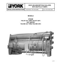
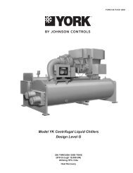
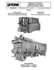


![[PDF] Catálogo Técnico YP Corrigido Corel 9 - Johnson Controls](https://img.yumpu.com/49244478/1/190x245/pdf-catalogo-taccnico-yp-corrigido-corel-9-johnson-controls.jpg?quality=85)