(STYLE G) R-134a (COOLING ONLY) - Johnson Controls
(STYLE G) R-134a (COOLING ONLY) - Johnson Controls
(STYLE G) R-134a (COOLING ONLY) - Johnson Controls

Create successful ePaper yourself
Turn your PDF publications into a flip-book with our unique Google optimized e-Paper software.
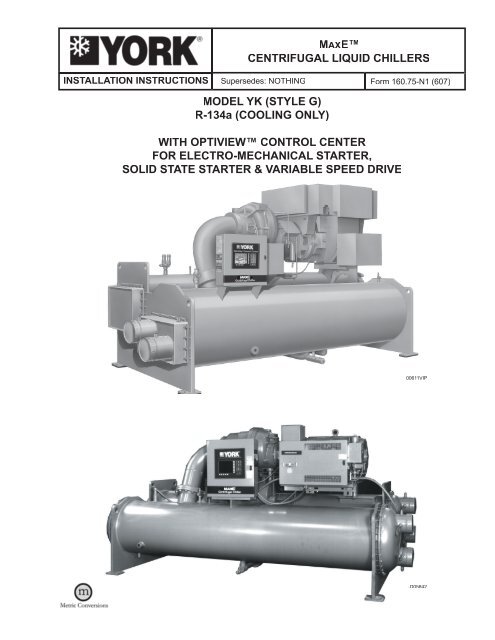
MAXE TM<br />
CENTRIFUGAL LIQUID CHILLERS<br />
INSTALLATION INSTRUCTIONS<br />
Supersedes: NOTHING Form 160.75-N1 (607)<br />
MODEL YK (<strong>STYLE</strong> G)<br />
R-<strong>134a</strong> (<strong>COOLING</strong> <strong>ONLY</strong>)<br />
WITH OPTIVIEW CONTROL CENTER<br />
FOR ELECTRO-MECHANICAL STARTER,<br />
SOLID STATE STARTER & VARIABLE SPEED DRIVE<br />
00611VIP<br />
LD05842
FORM 160.75-N1 (607)<br />
Compressor<br />
Codes<br />
ALLOWABLE COMPRESSOR/<br />
EVAPORATOR/CONDENSER/MOTOR COMBINATIONS<br />
Evaporator<br />
Codes<br />
YK MOD G COMBINATIONS<br />
Condenser<br />
Codes<br />
Q3 AP to AS AP to AS<br />
Q3, Q4<br />
CP to CS<br />
DP to DS<br />
CP to CS<br />
DP to DS<br />
Q4 EP to ET EP to ET<br />
Q5<br />
CP to CS<br />
DP to DS<br />
CP to CS<br />
DP to DS<br />
Q5, Q6, Q7, & P7 EP to ET EP to ET<br />
Motor Codes<br />
60 Hz 50 Hz<br />
CF-CT<br />
CH-CT<br />
5CC-5CO<br />
5CE-5CO<br />
Q5, Q6, Q7, & P7 FQ to FT FQ to FT CU-CY 5CP-5CU<br />
P8 GQ to GS EV to EX<br />
P8, P9<br />
H9<br />
HQ to HS<br />
JP to JS<br />
LQ to LS<br />
KP to KS, K2 to K4<br />
MQ to MS, M2 to M4<br />
FV to FX<br />
JP to JS<br />
LQ to LS<br />
KP to KS, K2 to K4<br />
MP to MS, M2 to M4<br />
K1 KT to KX, K5 to K7 KP to KS, K5 to K7<br />
K1, K2<br />
K3<br />
K4<br />
K7<br />
MQ to MS, M2 to M4<br />
NQ to NS, N2 to N4<br />
PQ to PS, P2 to P4<br />
QQ to QS, Q2 to Q4<br />
NQ to NS, N2 to N4<br />
QQ to QV, Q2 to Q4<br />
RQ, RS, RV, R3, R5, R7<br />
RP, RR, RT, R2, R4, R6<br />
SQ, SS, SV, S3, S5, S7<br />
XQ to XS, X2 to X4<br />
WP-WT, W1, W2, W4, W6<br />
ZQ to ZS, Z1 to Z4<br />
MP to MS, M2 to M4<br />
NP to NS, N2 to N4<br />
PQ to PS, P2 to P4<br />
QQ to QS, Q2 to Q4<br />
NP to NS, N2 to N4<br />
QQ to QS, Q2 to Q4<br />
RQ to RS, R2 to R4<br />
RQ to RS, R2 to R4<br />
SQ to SS, S2 to S4<br />
VP to VS, V2 to V5<br />
TP to TS, T2 to T5<br />
XQ to XS, X2 to X4<br />
WQ to WS, W1 to W4<br />
ZQ to ZS, Z1 to Z4<br />
CH-CZ<br />
CN-CA<br />
CW-DC<br />
DA-DJ<br />
DA-DJ<br />
DD-DL<br />
5CE-5CU<br />
5CK-5CW<br />
5CS-5DC<br />
5DA-5DH<br />
5DA-5DJ<br />
5DD-5DL<br />
NOMENCLATURE<br />
YK CF CF G4 — CM G S<br />
Special Modifications<br />
Model<br />
Evaporator Code<br />
Condenser Code<br />
Compressor Code<br />
Design Level<br />
Motor Code<br />
Power Supply<br />
– for 60 Hz<br />
5 for 50 Hz<br />
2<br />
JOHNSON CONTROLS
FORM 160.75-N1 (607)<br />
IMPORTANT!<br />
READ BEFORE PROCEEDING!<br />
GENERAL SAFETY GUIDELINES<br />
This equipment is a relatively complicated apparatus. During installation, operation maintenance or service,<br />
individuals may be exposed to certain components or conditions including, but not limited to: refrigerants,<br />
oils, materials under pressure, rotating components, and both high and low voltage. Each of these items<br />
has the potential, if misused or handled improperly, to cause bodily injury or death. It is the obligation and<br />
responsibility of operating/service personnel to identify and recognize these inherent hazards, protect<br />
themselves, and proceed safely in completing their tasks. Failure to comply with any of these requirements<br />
could result in serious damage to the equipment and the property in which it is situated, as well as severe<br />
personal injury or death to themselves and people at the site.<br />
This document is intended for use by owner-authorized operating/service personnel. It is expected that this<br />
individual posseses independent training that will enable them to perform their assigned tasks properly and<br />
safely. It is essential that, prior to performing any task on this equipment, this individual shall have read<br />
and understood this document and any referenced materials. This individual shall also be familiar with and<br />
comply with all applicable governmental standards and regulations pertaining to the task in question.<br />
SAFETY SYMBOLS<br />
The following symbols are used in this document to alert the reader to areas of potential hazard:<br />
DANGER indicates an imminently<br />
hazardous situation which, if not<br />
avoided, will result in death or serious<br />
injury.<br />
CAUTION identifies a hazard which<br />
could lead to damage to the machine,<br />
damage to other equipment and/or<br />
environmental pollution. Usually an<br />
instruction will be given, together with<br />
a brief explanation.<br />
WARNING indicates a potentially<br />
hazardous situation which, if not<br />
avoided, could result in death or serious<br />
injury.<br />
NOTE is used to highlight additional<br />
information which may be helpful to<br />
you.<br />
JOHNSON CONTROLS<br />
CHANGEABILITY OF THIS DOCUMENT<br />
In complying with YORK’s policy for continuous product improvement, the information contained in this<br />
document is subject to change without notice. While YORK makes no commitment to update or provide<br />
current information automatically to the manual owner, that information, if applicable, can be obtained by<br />
contacting the nearest YORK Applied Systems Service office.<br />
It is the responsibility of operating/service personnel to verify the applicability of these documents to<br />
the equipment in question. If there is any question in the mind of operating/service personnel as to the<br />
applicability of these documents, then prior to working on the equipment, they should verify with the owner<br />
whether the equipment has been modified and if current literature is available.<br />
3
TABLE OF CONTENTS<br />
DIMENSIONS ................................................................................................. 6<br />
CHILLER WEIGHTS ....................................................................................... 22<br />
MOTOR WEIGHTS ........................................................................................ 22<br />
INTRODUCTION ............................................................................................ 24<br />
General .................................................................................................. 24<br />
Field Assembed Units Only .................................................................... 24<br />
Shipment ................................................................................................ 24<br />
Inspection – Damage – Shortage ....................................................... 25<br />
Chiller Data Plate ................................................................................... 25<br />
Rigging ................................................................................................... 25<br />
Location ................................................................................................. 26<br />
Motors .................................................................................................... 26<br />
Foundation ............................................................................................. 26<br />
Clearance .............................................................................................. 26<br />
Isolators ................................................................................................. 27<br />
INSTALLATION .............................................................................................. 31<br />
Rigging Unit to Final Location ................................................................ 31<br />
Locating and Installing Isolator Pads ..................................................... 31<br />
Checking the Isolation Pad Deflection ................................................... 31<br />
Leveling the Unit .................................................................................... 31<br />
Installing Optional Spring Isolators ........................................................ 31<br />
Piping Connections ................................................................................ 31<br />
Evaporator and Condenser Water Piping .............................................. 32<br />
Refrigerant Relief Piping ........................................................................ 33<br />
Unit Piping ............................................................................................. 33<br />
Control Panel Positioning ...................................................................... 34<br />
Control Wiring ........................................................................................ 34<br />
Power Wiring ......................................................................................... 34<br />
Insulation ............................................................................................... 35<br />
Installation Check – Request for Start-up Service ............................... 35<br />
FORM 160.75-N1 (607)<br />
4<br />
LIST OF FIGURES<br />
FIG. 1 – Model YK MaxE Chiller ................................................................ 5<br />
FIG. 2 – Dimensions (P & Q Compressors – Ft-In) ....................................... 6<br />
FIG. 3 – Dimensions (P & Q Compressors – Metric) .................................... 7<br />
FIG. 4 – Dimensions (H Compressors – Ft-In) .............................................. 8<br />
FIG. 5 – Dimensions (H Compressors – Metric) ........................................... 9<br />
FIG. 6 – Dimensions (K Compressors – Ft-In) .............................................. 10<br />
FIG. 7 – Dimensions (K Compressors – Metric) ............................................ 11<br />
FIG. 8 – Dimensions Evaporator Compact Waterboxes ................................ 12<br />
FIG. 9 – Dimensions Condenser Compact Waterboxes ............................... 13<br />
FIG. 10 – Dimensions Evaporator Compact Waterboxes A thru K ................. 14<br />
FIG. 11 – Dimensions Evaporator Compact Waterboxes M thru Z ................. 15<br />
FIG. 12 – Dimensions Condenser Compact Waterboxes ............................... 16<br />
FIG. 13 – Dimensions Evaporator Nozzle Arrangements ................................ 18<br />
FIG. 14 – Dimensions Condenser Nozzle Arrangements ................................ 19<br />
FIG. 15 – Dimensions Evaporator Marine Waterboxes ................................... 20<br />
FIG. 16 – Dimensions Condenser Marine Waterboxes ................................... 21<br />
FIG. 17 – Rigging ............................................................................................ 26<br />
FIG. 18 – Neoprene Isolators ......................................................................... 27<br />
FIG. 19 – Neoprene Isolators ......................................................................... 28<br />
FIG. 20 – Spring Isolators ............................................................................... 29<br />
FIG. 21 – Spring Isolators ............................................................................... 30<br />
JOHNSON CONTROLS
FORM 160.75-N1 (607)<br />
LIST OF FIGURES (CON'T)<br />
FIG. 22 – Schematic for a Typical Piping Arrangement ................................... 32<br />
FIG. 23 – Typical Refrigerant Vent Piping ....................................................... 33<br />
FIG. 24 – Control Panel Positioning ................................................................ 34<br />
FIG. 25 – Unit Insulation .................................................................................. 35<br />
LIST OF TABLES<br />
TABLE 1 – Approximate Unit Weight Including Motor .................................... 22<br />
TABLE 2A – Evaporator Marine Waterbox Weights ...................................... 23<br />
TABLE 2B – Condenser Marine Waterbox Weights ...................................... 23<br />
COMPRESSOR<br />
OPTIVIEW<br />
CONTROL<br />
CENTER<br />
MOTOR<br />
CONDENSER<br />
EVAPORATOR<br />
FIG. 1 – MODEL YK MaxE CHILLER<br />
00611VIP<br />
JOHNSON CONTROLS<br />
5
FORM 160.75-N1 (607)<br />
<br />
<br />
<br />
P & Q COMPRESSOR UNITS (STANDARD)<br />
<br />
<br />
<br />
<br />
<br />
<br />
<br />
<br />
<br />
<br />
<br />
<br />
<br />
<br />
<br />
<br />
<br />
LD07134<br />
ADDITIONAL OPERATING HEIGHT CLEARANCE TO FLOOR<br />
TYPE OF CHILLER MOUNTING<br />
M<br />
NEOPRENE PAD ISOLATORS 1-3/4"<br />
SPRING ISOLATORS 1" DEFLECTION 1"<br />
DIRECT MOUNT 3/4"<br />
P7, Q7 COMPRESSOR<br />
EVAPORATOR – CONDENSER SHELL CODES<br />
E–E<br />
F–F<br />
A 6'–2" 6'–2"<br />
B 7'–6 1/2" 7'–6 1/2"<br />
C 1'–7 1/2" 1'–7 1/2"<br />
D 1'–5 1/2" 1'–5 1/2"<br />
E 12'–0" 16'–0"<br />
Q3 COMPRESSOR<br />
EVAPORATOR-CONDENSER SHELL CODES<br />
A-A C-C D-D<br />
A 5'-1" 5'-6" 5'-6"<br />
B 7'-0" 7'-3 3/4" 7'-3 3/4"<br />
C 1'-3 1/2" 1'-5 1/2" 1'-5 1/2"<br />
D 1'-3" 1'-3 1/2" 1'-3 1/2"<br />
E 12'-0" 12'-0" 16'-0"<br />
Q4 COMPRESSOR<br />
EVAPORATOR-CONDENSER SHELL CODE<br />
C-C D-D E-E<br />
A 5'-6" 5'-6" 7'-0"<br />
B 7'-2 1/2" 7'-2 1/2" 7'-8 1/2"<br />
C 1'-5 1/2" 1'-5 1/2" 1'-7 1/2"<br />
D 1'-3 1/2" 1'-3 1/2" 1'-5 1/2"<br />
E 12'-0" 16'-0" 12'-0"<br />
P8 COMPRESSOR<br />
EVAPORATOR – CONDENSER SHELL CODES<br />
G–E H–F J–J L–L<br />
A 6'–11" 6'–11" 7'–6 1/2" 7'–6 1/2"<br />
B 10'–3 1/2" 10'–3 1/2" 10'–9 1/2" 10'–9 1/2"<br />
C 2'–0" 2'–0" 2'–1 1/4" 2'–1 1/4"<br />
D 1'–5 1/2" 1'–5 1/2" 1'–8" 1'–8"<br />
E 12'–0" 16'–0" 12'–0" 16'–0"<br />
Q5 COMPRESSOR<br />
EVAPORATOR-CONDENSER SHELL CODES<br />
C-C D-D E-E F-F<br />
A 5'-6" 5'-6" 7'-0" 7'-0"<br />
B 7'-10 5/8" 7'-10 5/8" 8'-3" 8'-3"<br />
C 1'-5 1/2" 1'-5 1/2" 1'-7 1/2" 1'-7 1/2"<br />
D 1'-3 1/2" 1'-3 1/2" 1'-5 1/2" 1'-5 1/2"<br />
E 12'-0" 16'-0" 12'-0" 16'-0"<br />
P9 COMPRESSOR<br />
EVAPORATOR – CONDENSER SHELL CODES<br />
H–F J–J L–L<br />
A 6'–11" 7'–6 1/2" 7'–6 1/2"<br />
B 9'–11 7/8" 10'–6" 10'–6"<br />
C 2'–0" 2'–1 1/4" 2'–1 1/4"<br />
D 1'–5 1/2" 1'–8" 1'–8"<br />
E 16'–0" 12'–0" 16'–0"<br />
Q6 COMPRESSOR<br />
EVAPORATOR-CONDENSER SHELL CODES<br />
E-E<br />
F-F<br />
A 7'-0" 7'-0"<br />
B 8'-3" 8'-3"<br />
C 1'-7 1/2" 1'-7 1/2"<br />
D 1'-5 1/2" 1'-5 1/2"<br />
E 12'-0" 16'-0"<br />
NOTES:<br />
1. All dimensions are approximate.<br />
2. For compact water boxes (shown above), determine overall unit length by adding water box depth to tube sheet length.<br />
3. Water nozzles can be located on either end of unit. Add 1/2" (13 mm) to nozzle length for flanges connections.<br />
4. To determine overall height, add 7/8" (22 mm) for isolators.<br />
5. Use of motors with motor hoods may increase overall unit dimensions.<br />
FIG. 2 – DIMENSIONS – P & Q COMPRESSOR UNITS (FT–IN)<br />
6<br />
JOHNSON CONTROLS
FORM 160.75-N1 (607)<br />
<br />
<br />
<br />
P & Q COMPRESSOR UNITS (METRIC)<br />
<br />
<br />
<br />
<br />
<br />
<br />
<br />
<br />
<br />
<br />
<br />
<br />
<br />
<br />
<br />
<br />
<br />
LD07134<br />
ADDITIONAL OPERATING HEIGHT CLEARANCE<br />
TYPE OF CHILLER MOUNTING<br />
M<br />
NEOPRENE PAD ISOLATORS 44<br />
SPRING ISOLATORS 25mm DEFLECTION 25<br />
DIRECT MOUNT 19<br />
Q3 COMPRESSOR<br />
EVAPORATOR-CONDENSER SHELL CODES<br />
A-A C-C D-D<br />
A 1549 1676 1676<br />
B 2134 2229 2229<br />
C 394 445 445<br />
D 381 394 394<br />
E 3658 3658 4877<br />
P7, Q7 COMPRESSOR<br />
EVAPORATOR – CONDENSER SHELL CODES<br />
E–E<br />
F–F<br />
A 1,880 1,880<br />
B 2,299 2,299<br />
C 495 495<br />
D 445 445<br />
E 3,658 4,877<br />
Q4 COMPRESSOR<br />
EVAPORATOR-CONDENSER SHELL CODE<br />
C-C D-D E-E<br />
A 1676 1676 2134<br />
B 2197 2197 2350<br />
C 445 445 495<br />
D 394 394 445<br />
E 3658 4877 3658<br />
P8 COMPRESSOR<br />
EVAPORATOR – CONDENSER SHELL CODES<br />
E–E F–F G–G H–H<br />
A 2,108 2,108 2,299 2,299<br />
B 3,137 3,137 3,289 3,289<br />
C 610 610 641 641<br />
D 445 445 508 508<br />
E 3,658 4,877 3,658 4,877<br />
Q5 COMPRESSOR<br />
EVAPORATOR-CONDENSER SHELL CODES<br />
C-C D-D E-E F-F<br />
A 1676 1676 2134 2134<br />
B 2403 2403 2515 2515<br />
C 445 445 495 495<br />
D 394 394 445 445<br />
E 3658 4877 3658 4877<br />
P9 COMPRESSOR<br />
EVAPORATOR – CONDENSER SHELL CODES<br />
H–F J–J L–L<br />
A 2,108 2,299 2,299<br />
B 3,045 3,200 3,200<br />
C 610 641 641<br />
D 445 508 508<br />
E 4,877 3,658 4,877<br />
NOTES:<br />
1. All dimensions are approximate.<br />
2. For compact water boxes (shown above), determine overall unit length by adding water box depth to tube sheet length.<br />
3. Water nozzles can be located on either end of unit. Add 13 mm (1/2 inch) to nozzle length for flanges connections.<br />
4. To determine overall height, add 22 mm (7/8 inch) for isolators.<br />
5. Use of motors with motor hoods may increase overall unit dimensions.<br />
FIG. 3 – DIMENSIONS – P & Q COMPRESSOR UNITS (mm)<br />
Q6 COMPRESSOR<br />
EVAPORATOR-CONDENSER SHELL CODES<br />
E-E<br />
F-F<br />
A 2134 2134<br />
B 2515 2515<br />
C 495 495<br />
D 445 445<br />
E 3658 4877<br />
JOHNSON CONTROLS<br />
7
FORM 160.75-N1 (607)<br />
H COMPRESSOR UNITS (STANDARD)<br />
LD07135<br />
ADDITIONAL OPERATING HEIGHT CLEARANCE TO FLOOR<br />
TYPE OF CHILLER MOUNTING<br />
M<br />
NEOPRENE PAD ISOLATORS 1 3/4"<br />
SPRING ISOLATORS 1" DEFLECTION 1"<br />
DIRECT MOUNT 3/4"<br />
H9 COMPRESSORS<br />
EVAP. – COND. SHELL CODES<br />
K–K M–M<br />
A 7'–6 1/2" 9'–0"<br />
B 9'–5" 10'–2"<br />
C 2'–1 1/4" 2'–4 1/2"<br />
D 1'–8" 1'–11"<br />
E 14'–0" 14'–0"<br />
NOTES:<br />
1. All dimensions are approximate.<br />
2. For compact water boxes (shown above), determine overall unit length by adding water box depth to tube sheet length.<br />
3. Water nozzles can be located on either end of unit. Add 1/2" (13 mm) to nozzle length for flanges connections.<br />
4. To determine overall height, add 7/8" (22 mm) for isolators.<br />
5. Use of motors with motor hoods may increase overall unit dimensions.<br />
FIG. 4 – DIMENSIONS – H COMPRESSOR UNITS (FT–IN)<br />
8<br />
JOHNSON CONTROLS
FORM 160.75-N1 (607)<br />
H COMPRESSOR UNITS (METRIC)<br />
178<br />
LD03886<br />
ADDITIONAL OPERATING HEIGHT CLEARANCE<br />
TYPE OF CHILLER MOUNTING<br />
M<br />
NEOPRENE PAD ISOLATORS 44<br />
SPRING ISOLATORS 25mm DEFLECTION 25<br />
DIRECT MOUNT 19<br />
H9 COMPRESSORS<br />
EVAP. – COND. SHELL CODES<br />
K–K M–M<br />
A 2,300 2,743<br />
B 2,872 3,100<br />
C 641 724<br />
D 508 648<br />
E 4,268 4,268<br />
NOTES:<br />
1. All dimensions are approximate.<br />
2. For compact water boxes (shown above), determine overall unit length by adding water box depth to tube sheet length.<br />
3. Water nozzles can be located on either end of unit. Add 13 mm (1/2 inch) to nozzle length for flanges connections.<br />
4. To determine overall height, add 22 mm (7/8 inch) for isolators.<br />
5. Use of motors with motor hoods may increase overall unit dimensions.<br />
FIG. 5 – DIMENSIONS – H COMPRESSOR UNITS (mm)<br />
JOHNSON CONTROLS<br />
9
FORM 160.75-N1 (607)<br />
K COMPRESSOR UNITS - (STANDARD)<br />
<br />
<br />
<br />
<br />
<br />
<br />
<br />
<br />
<br />
<br />
<br />
<br />
<br />
<br />
<br />
<br />
<br />
<br />
<br />
<br />
<br />
LD07136<br />
K1 Compressor, Evaporator-Condenser Shell Codes<br />
K-K M-M N-N P-P Q-Q<br />
A 7'-6 1/2" 8'-7" 8'-7" 9'-1 1/2" 9'-1 1/2" Additional Operating Height Clearance<br />
B - 11'-4" 11'-4" 11'-5 1/2" 11'-5 1/2" Type of Chiller Mounting M<br />
C 2'-1 1/4" 2'-4 1/2" 2'-4 1/2" 2'-5 1/2" 2'-5 1/2" Neoprene Pad Isolators 1 3/4"<br />
D 1'-8" 1'-11" 1'-11" 2'-1 1/4" 2'-1 1/4" Spring Isolators 1" Deflection 1"<br />
E 14'-0" 14'-0" 16'-0" 14'-0" 16'-0" Direct Mount 3/4"<br />
K2 Compressor, Evaporator-Condenser Shell Codes<br />
K3 Compressor, Evap.-Cond. Shell Codes<br />
M-M N-N P-P Q-Q N-N Q-Q R-R<br />
A 8'-7" 8'-7" 9'-1 1/2" 9'-1 1/2" A 8'-7" 9'-1 1/2" 9'-9"<br />
B 11'-4" 11'-4" 11'-5" 11'-5" B - 11'-6" 11'-10"<br />
C 2'-4 1/2" 2'-4 1/2" 2'-5 1/2" 2'-5 1/2" C 2'-4 1/2" 2'-5 1/2" 2'-8"<br />
D 1'-11" 1'-11" 2'-1 1/4" 2'-1 1/4" D 1'-11" 2'-1 1/4" 2'-3 1/2"<br />
E 14'-0" 16'-0" 14'-0" 16'-0" E 16'-0" 16'-0" 16'-0"<br />
K4 Compressor, Evaporator-Condenser Shell Codes<br />
K7 Compressor, Evap.-Cond Shell Codes<br />
R-R S-S S-V X-T X-X W-W Z-Z<br />
A 9'-9" 9'-9" 10'-3" 10'-10" 11'-3" A 10'-3" 11'-3"<br />
B - - - - - B 12'-2" 12'-10"<br />
C 2'-8" 2'-8" 2'-8" 2'-11 1/2" 2'-11 1/2" C 2'-8" 2'-11 1/2"<br />
D 2'-3 1/2" 2'-3 1/2" 2'-5 1/2" 2'-5 1/2" 2'-8" D 2'-5 1/2" 2'-8"<br />
E 16'-0" 18'-0" 18'-0" 16'-0" 16'-0" E 22'-0" 18'-0"<br />
NOTES:<br />
1. All dimensions are approximate.<br />
2. For compact water boxes (shown above), determine overall unit length by adding water box depth to tube sheet length.<br />
3. Water nozzles can be located on either end of unit. Add 1/2" (13 mm) to nozzle length for flanges connections.<br />
4. To determine overall height, add 7/8" (22 mm) for isolators.<br />
5. Use of motors with motor hoods may increase overall unit dimensions.<br />
FIG. 6 – DIMENSIONS – K COMPRESSOR UNITS (FT–IN)<br />
10<br />
JOHNSON CONTROLS
FORM 160.75-N1 (607)<br />
K COMPRESSOR UNITS - (METRIC)<br />
<br />
<br />
<br />
<br />
<br />
<br />
<br />
<br />
<br />
<br />
<br />
<br />
<br />
<br />
<br />
<br />
<br />
<br />
<br />
<br />
<br />
LD07139<br />
K1 Compressor, Evaporator-Condenser Shell Codes<br />
K-K M-M N-N P-P Q-Q<br />
A 2299 2616 2616 2781 2781 Additional Operating Height Clearance<br />
B - 3454 3454 3493 3493 Type of Chiller Mounting M<br />
C 641 724 724 749 749 Neoprene Pad Isolators 44<br />
D 508 584 584 641 641 Spring Isolators 1" Deflection 25<br />
E 4267 4267 4877 4267 4877 Direct Mount 19<br />
K2 Compressor, Evaporator-Condenser Shell Codes<br />
K3 Compressor, Evap.-Cond. Shell Codes<br />
M-M N-N P-P Q-Q N-N Q-Q R-R<br />
A 2616 2616 2781 2781 A 2616 2781 2972<br />
B 3454 3454 3480 3480 B - 3505 3607<br />
C 724 724 749 749 C 724 749 813<br />
D 584 584 641 641 D 584 641 699<br />
E 4267 4877 4267 4877 E 4877 4877 4877<br />
K4 Compressor, Evaporator-Condenser Shell Codes<br />
K7 Compressor, Evap.-Cond Shell Codes<br />
R-R S-S S-V X-T X-X W-W Z-Z<br />
A 2972 2972 3124 3302 3429 A 3124 3429<br />
B - - - - - B 3708 3912<br />
C 813 813 813 902 902 C 813 902<br />
D 699 699 749 749 813 D 749 813<br />
E 4877 5486 5486 4877 4877 E 6706 5486<br />
NOTES:<br />
1. All dimensions are approximate.<br />
2. For compact water boxes (shown above), determine overall unit length by adding water box depth to tube sheet length.<br />
3. Water nozzles can be located on either end of unit. Add 13 mm (1/2 inch) to nozzle length for flanges connections.<br />
4. To determine overall height, add 22 mm ( 7/8 inch) for isolators.<br />
5. Use of motors with motor hoods may increase overall unit dimensions.<br />
FIG. 7 – DIMENSIONS – K COMPRESSOR UNITS (mm)<br />
JOHNSON CONTROLS<br />
11
FORM 160.75-N1 (607)<br />
EVAPORATOR COMPACT WATERBOXES - Ft - In (mm)<br />
F<br />
F<br />
ONE PASS EVAPORATORS, CODES<br />
DIM. A C,D E,F G,H J,K,L M,N P,Q R,S,W X,Z<br />
F<br />
1'-2 1/4"<br />
(362)<br />
1'-3"<br />
(381)<br />
1'-3 1/2"<br />
(394)<br />
1'-2 7/8"<br />
(378)<br />
1'-4 5/8"<br />
(422)<br />
1'-11 3/4"<br />
(603)<br />
1'-11 3/4"<br />
(603)<br />
2'-0 3/4"<br />
(629)<br />
-<br />
G<br />
F<br />
TWO PASS EVAPORATORS, CODES<br />
DIM. A C,D E,F G,H J,K,L M,N P,Q R,S,W X,Z<br />
F<br />
1'-2 1/4"<br />
(362)<br />
1'-3"<br />
(381)<br />
1'-3 1/2"<br />
(394)<br />
1'-2 7/8"<br />
(378)<br />
1'-4 5/8"<br />
(422)<br />
1'-11 3/4"<br />
(603)<br />
1'-11 3/4"<br />
(603)<br />
2'-0 3/4"<br />
(629)<br />
-<br />
G<br />
0'-6 1/2"<br />
(165)<br />
0'-7"<br />
(178)<br />
0'-7 1/2"<br />
(191)<br />
0'-8 1/4"<br />
(210)<br />
0'-9 1/2"<br />
(241)<br />
1'-3"<br />
(381)<br />
1'-3"<br />
(381)<br />
1'-4 3/4"<br />
(425)<br />
-<br />
F<br />
F<br />
THREE PASS EVAPORATORS, CODES<br />
DIM. A C,D E,F G,H J,K,L M,N P,Q R,S,W X,Z<br />
F<br />
1'-2 1/4"<br />
(362)<br />
1'-3"<br />
(381)<br />
1'-3 1/2"<br />
(394)<br />
1'-2 7/8"<br />
(378)<br />
1'-4 5/8"<br />
(422)<br />
1'-11 3/4"<br />
(603)<br />
1'-11 3/4"<br />
(603)<br />
2'-0 3/4"<br />
(629)<br />
-<br />
LD07619<br />
See Notes on page 17.<br />
FIG. 8 – DIMENSIONS – EVAPORATOR COMPACT WATERBOXES<br />
12<br />
JOHNSON CONTROLS
FORM 160.75-N1 (607)<br />
CONDENSER COMPACT WATERBOXES - Ft - In (mm)<br />
H<br />
H<br />
ONE PASS CONDENSERS, CODES<br />
DIM. A C,D E,F J,K,L M,N P,Q R,S T,V,W X,Z<br />
H<br />
1'-1 7/8"<br />
(352)<br />
1'-1 7/8"<br />
(352)<br />
1'-3"<br />
(381)<br />
1'-4"<br />
(406)<br />
1'-2 7/8"<br />
(378)<br />
1'-4 7/8"<br />
(429)<br />
- -<br />
1'-9 3/4"<br />
(552)<br />
J<br />
H<br />
TWO PASS CONDENSERS, CODES<br />
DIM. A C,D E,F J,K,L M,N P,Q R,S T,V,W X,Z<br />
H<br />
1'-1 7/8"<br />
(352)<br />
1'-1 7/8"<br />
(352)<br />
1'-3"<br />
(381)<br />
1'-4"<br />
(406)<br />
1'-2 7/8"<br />
(378)<br />
1'-4 7/8"<br />
(429)<br />
- -<br />
1'-9 3/4"<br />
(552)<br />
J<br />
0'-5 7/8"<br />
(149)<br />
0'-6 1/2"<br />
(165)<br />
0'-7"<br />
(178)<br />
0'-7 1/2"<br />
(191)<br />
0'-7 3/4"<br />
(197)<br />
0'-9 1/2"<br />
(241)<br />
- -<br />
1'-1 7/8"<br />
(352)<br />
H<br />
H<br />
THREE PASS CONDENSERS, CODES<br />
DIM. A C,D E,F J,K,L M,N P,Q R,S T,V,W X,Z<br />
H<br />
1'-1 7/8"<br />
(352)<br />
1'-1 7/8"<br />
(356)<br />
1'-3"<br />
(381)<br />
1'-4"<br />
(406)<br />
1'-2 7/8"<br />
(378)<br />
1'-4 7/8"<br />
(429)<br />
- -<br />
1'-9 3/4"<br />
(552)<br />
LD07619a<br />
See Notes on page 17.<br />
FIG. 9 – DIMENSIONS – CONDENSER COMPACT WATERBOXES<br />
JOHNSON CONTROLS<br />
13
FORM 160.75-N1 (607)<br />
EVAPORATORS – COMPACT WATER BOXES – A THRU K EVAPORATORS<br />
AA<br />
M<br />
EVAP.<br />
A<br />
C<br />
COMPRESSOR END<br />
FRONT<br />
OF<br />
UNIT<br />
FLOOR LINE<br />
EVAP.<br />
H<br />
C<br />
MOTOR END<br />
AA<br />
M<br />
NO. OF<br />
PASSES<br />
1<br />
NOZZLE<br />
ARRANGEMENTS<br />
EVAPORATOR<br />
IN OUT<br />
A<br />
H<br />
H<br />
A<br />
1-PASS<br />
DD<br />
BB<br />
M<br />
EVAP.<br />
B<br />
C<br />
C<br />
COMPRESSOR END<br />
FRONT<br />
OF<br />
UNIT<br />
FLOOR LINE<br />
EVAP.<br />
J<br />
K<br />
C<br />
MOTOR END<br />
DD<br />
BB<br />
M<br />
NOZZLE<br />
ARRANGEMENTS<br />
NO. OF EVAPORATOR<br />
PASSES IN OUT<br />
C B<br />
2<br />
K J<br />
2-PASS<br />
DD<br />
BB<br />
F<br />
G<br />
EVAP.<br />
FRONT<br />
OF<br />
UNIT<br />
M C C<br />
FLOOR LINE<br />
COMPRESSOR END<br />
MOTOR END<br />
N<br />
P<br />
EVAP.<br />
BB<br />
M<br />
DD<br />
NOZZLE<br />
ARRANGEMENTS<br />
NO. OF EVAPORATOR<br />
PASSES IN OUT<br />
G N<br />
3<br />
P F<br />
3-PASS<br />
LD07598a<br />
CONDENSER<br />
SHELL CODE<br />
A<br />
C,D<br />
E,F<br />
G,H<br />
J,K,L<br />
See Notes on page 17.<br />
COMPACT WATER BOXES - 150 PSI ROUND<br />
NOZZLE PIPE SIZE IN (mm)<br />
EVAPORATOR NOZZLE DIMENSIONS FT-IN (mm)<br />
NO. OF PASSES 1-PASS 2-PASS 3-PASS<br />
1 2 3 C AA 5 BB 5 DD 5 BB 5 DD 5<br />
8<br />
6<br />
4 1'-3 1/2" 1'-10" 1'-2" 2'-6" 1'-2" 2'-6"<br />
(203) (152) (101) (394) (559) (356) (762) (356) (762)<br />
10<br />
8<br />
6 1'-5 1/2" 2'-0" 1'-3" 2'-9" 1'-3" 2'-9"<br />
(254) (203) (152) (445) (610) (381) (838) (381) (838)<br />
14<br />
10<br />
8<br />
1'-7" 2'-2" 1'-4" 3'-0" 1'-4" 3'-0"<br />
(355) (254) (203) (483) (660) (406) (914) (406) (914)<br />
14<br />
10<br />
8<br />
2'-0" 2'-3 1/2" 1'-4" 3'-3" 1'-4" 3'-3"<br />
(355) (254) (203) (610) (699) (406) (991) (406) (991)<br />
16<br />
12<br />
10 2'-1 1/4" 2'-6" 1'-4 1/2" 3'-7 1/2" 1'-5" 3'-7"<br />
(406) (305) (254) (641) (762) (419) (1105) (432) (1092)<br />
FIG. 10 – DIMENSIONS – EVAPORATOR COMPACT WATERBOXES A THRU K EVAPORATORS<br />
14<br />
JOHNSON CONTROLS
FORM 160.75-N1 (607)<br />
EVAPORATORS – COMPACT WATER BOXES – M THRU Z EVAPORATORS<br />
<br />
<br />
<br />
<br />
<br />
<br />
<br />
<br />
SHELL<br />
CODES<br />
M–Z<br />
1 PASS<br />
IN OUT<br />
A H<br />
H A<br />
<br />
<br />
<br />
<br />
<br />
<br />
<br />
<br />
<br />
<br />
<br />
<br />
<br />
<br />
<br />
<br />
<br />
<br />
<br />
<br />
<br />
<br />
<br />
<br />
SHELL<br />
CODES<br />
M–Z<br />
2 PASS<br />
IN OUT<br />
B C<br />
C B<br />
J K<br />
K J<br />
<br />
<br />
<br />
<br />
<br />
<br />
<br />
<br />
SHELL<br />
CODES<br />
M–Z<br />
3 PASS<br />
IN OUT<br />
F N<br />
N F<br />
<br />
<br />
<br />
<br />
<br />
<br />
<br />
<br />
LD07173a<br />
EVAPORATOR<br />
SHELL CODE<br />
M,N<br />
P,Q<br />
RP, RR, RT,<br />
R2, R4, R6, W<br />
RQ, RS, RV,<br />
R3, R4, R5, S<br />
X,Z<br />
See Notes on page 17.<br />
COMPACT WATER BOXES - 150 PSI RECTANGULAR<br />
NOZZLE PIPE SIZE IN (mm)<br />
EVAPORATOR NOZZLE DIMENSIONS FT-IN (MM)<br />
NO. OF PASSES 1-PASS 2-PASS 3-PASS<br />
1 2 3 C AA 5 AA 5 EE AA 5<br />
18<br />
(457)<br />
18<br />
(457)<br />
20<br />
(508)<br />
20<br />
(508)<br />
20<br />
(508)<br />
14<br />
(356)<br />
14<br />
(356)<br />
18<br />
(457)<br />
18<br />
(457)<br />
18<br />
(457)<br />
12<br />
(304)<br />
12<br />
(304)<br />
14<br />
(356)<br />
14<br />
(356)<br />
14<br />
(356)<br />
2'-4 1/2"<br />
(724)<br />
2'-5 1/2"<br />
(749)<br />
2'-8"<br />
(813)<br />
2'-8"<br />
(813)<br />
2'-11 1/2"<br />
(902)<br />
2'-2"<br />
(660)<br />
2'-2 3/4"<br />
(679)<br />
2'-7 1/16"<br />
(789)<br />
2'-8 1/4"<br />
(819)<br />
2'-10 1/2"<br />
(876)<br />
2'-2"<br />
(660)<br />
2'-2 3/4"<br />
(679)<br />
2'-7 1/16"<br />
(789)<br />
2'-8 1/4"<br />
(819)<br />
2'-10 1/2"<br />
(876)<br />
1'-1"<br />
(330)<br />
1'-1"<br />
(330)<br />
1'-3"<br />
(381)<br />
1'-3"<br />
(381)<br />
1'-3"<br />
(381)<br />
2'-2"<br />
(660)<br />
2'-2 3/4"<br />
(679)<br />
2'-7 1/16"<br />
(789)<br />
2'-8 1/4"<br />
(819)<br />
2'-10 1/2"<br />
(876)<br />
FIG. 11 – DIMENSIONS – EVAPORATOR COMPACT WATERBOXES M THRU Z EVAPORATORS<br />
JOHNSON CONTROLS<br />
15
FORM 160.75-N1 (607)<br />
CONDENSER – COMPACT WATER BOXES – STANDARD (mm)<br />
FRONT<br />
OF UNIT<br />
1-PASS<br />
CC<br />
P<br />
COND.<br />
FLOOR<br />
LINE<br />
Q<br />
COND.<br />
CC<br />
NOZZLE<br />
ARRANGEMENTS<br />
NO. OF<br />
PASSES<br />
1<br />
COND.<br />
IN OUT<br />
P Q<br />
Q P<br />
M<br />
D<br />
COMPRESSOR END<br />
D<br />
MOTOR END<br />
M<br />
FRONT<br />
OF UNIT<br />
2-PASS<br />
DD<br />
BB<br />
S<br />
R<br />
COND.<br />
FLOOR<br />
LINE<br />
U<br />
T<br />
COND.<br />
BB<br />
DD<br />
NOZZLE<br />
ARRANGEMENTS<br />
NO. OF COND.<br />
PASSES IN OUT<br />
R S<br />
2<br />
T U<br />
M<br />
D<br />
D<br />
M<br />
COMPRESSOR END<br />
MOTOR END<br />
FRONT<br />
OF UNIT<br />
3-PASS<br />
DD<br />
BB<br />
W<br />
V<br />
COND.<br />
FLOOR<br />
LINE<br />
Y<br />
X<br />
COND.<br />
BB<br />
DD<br />
NOZZLE<br />
ARRANGEMENTS<br />
NO. OF COND.<br />
PASSES IN OUT<br />
v y<br />
3<br />
x w<br />
16<br />
M<br />
D<br />
COMPRESSOR END<br />
CONDENSER<br />
SHELL CODE<br />
A<br />
C,D<br />
E,F<br />
J,K,L<br />
M,N<br />
P,Q<br />
R,S<br />
T,V,W<br />
X,Z<br />
See Notes on page 17.<br />
D<br />
MOTOR END<br />
M<br />
COMPACT WATER BOXES - 150 PSI ROUND<br />
NOZZLE PIPE SIZE IN (mm) CONDENSER NOZZLE DIMENSIONS FT-IN (mm)<br />
NO. OF PASSES 1-PASS 2-PASS 3-PASS<br />
1 2 3 D CC 5 BB 5 DD 5 BB 5 DD 5<br />
10 6 6 1'-3" 2'-4" 1'-9 1/2" 2'-10 1/2" 1'-9 1/2" 2'-10 1/2"<br />
(254) (152) (152) (381) (711) (546) (876) (546) (876)<br />
12 8 6 1'-3 1/2" 2'-6" 1'-10 3/8" 3'-1 5/8" 1'-10 3/8" 3'-1 5/8"<br />
(305) (203) (152) (394) (762) (568) (956) (568) (956)<br />
14 10 8 1'-5 1/2" 2'-8" 1'-11 3/4" 3'-4 1/4" 1'-11 3/4" 3'-4 1/4"<br />
(356) (254) (203) (445) (813) (603) (1022) (603) (1022)<br />
16 10 10 1'-8" 3'-0" 2'-2" 3'-10" 2'-1 1/4" 3'-10 1/4"<br />
(406) (254) (254) (508) (914) (660) (1168) (641) (1175)<br />
20 14 10 1'-11" 3'-6" 2'-6 1/4" 4'-5 3/4" 2'-6 1/4" 4'-5 3/4"<br />
(508) (356) (254) (584) (1067) (768) (1365) (768) (1365)<br />
20 16 14 2'-1 1/4" 3'-8" 2'-8 1/4" 4'-7 3/4" 2'-6 3/4" 4'-7 3/4"<br />
(508) (406) (356) (641) (1118) (819) (1416) (781) (1416)<br />
20 18 14 2'-3 1/2" 3'-10 1/2"<br />
(508) (457) (356) (699) (1181)<br />
- - - -<br />
24 18 16 2'-5 1/2" 3'-11 1/2" 2'-10 1/2" 5'-0 1/2" 2'-10 1/2" 5'-0 1/2"<br />
(610) (457) (406) (749) (1207) (876) (1537) (876) (1537)<br />
24 20 16 2'-8" 4'-1 1/4" 2'-9 1/2" 5'-5" 2'-9 1/2" 5'-5"<br />
(610) (508) (406) (813) (1251) (851) (1651) (851) (1651)<br />
FIG. 12 – DIMENSIONS – CONDENSER COMPACT WATERBOXES - STANDARD (mm)<br />
LD07131a<br />
JOHNSON CONTROLS
FORM 160.75-N1 (607)<br />
NOTES:<br />
1. Standard water nozzles are furnished as welding stub-outs with grooves, allowing the option of welding,<br />
flanges, or use of Victaulic couplings. Factory-installed, class 150 (ANSI B16.5, round slip-on, forged<br />
carbon steel with 1/16" raised face), water flanged nozzles are optional (add 1/2" to nozzle length).<br />
Companion flanges, nuts, bolts, and gaskets are not furnished.<br />
2. One-, two- and three-pass nozzle arrangements are available only in pairs shown and for all shell codes.<br />
Any pair of evaporator nozzles may be used in combination with any pair of condenser nozzles.<br />
3. Evaporator and condenser water must enter the water box through the bottom connection to achieve<br />
rated performance.<br />
4. Connected piping should allow for removal of compact water boxes for tube access and cleaning.<br />
5. Add dimension "M" as shown on the unit dimensions page for the appropriate isolator type.<br />
6. Standard 150 PSI design pressure boxes shown.<br />
JOHNSON CONTROLS<br />
17
FORM 160.75-N1 (607)<br />
EVAPORATOR – NOZZLE ARRANGEMENTS – STANDARD (mm)<br />
EVAPORATOR<br />
1-PASS<br />
IN OUT<br />
1 6<br />
6 1<br />
EVAPORATOR<br />
2-PASS<br />
IN OUT<br />
2 3<br />
7 8<br />
F<br />
EVAPORATOR<br />
3-PASS<br />
IN OUT<br />
5 10<br />
9 4<br />
LD01342b<br />
EVAPORATOR<br />
SHELL CODE<br />
A<br />
C,D<br />
E,F<br />
G,H<br />
J,K,L<br />
M,N<br />
EVAPORATOR NOZZLE DIMENSIONS FT-IN (mm)<br />
1-PASS 2-PASS 3-PASS<br />
F I F G I F I<br />
1'-7"<br />
0'-8 3/4"<br />
1'-5"<br />
0'-6 1/2" 0'-7 3/4"<br />
1'-5"<br />
0'-7 3/4"<br />
(483)<br />
(222)<br />
(432)<br />
(165)<br />
(197)<br />
(432)<br />
(197)<br />
1'-10 3/4' 0'-10 5/8" 1'-8 5/8"<br />
0'-7"<br />
0'-9 1/2" 1'-8 5/8" 0'-9 1/2"<br />
(578)<br />
(270)<br />
(524)<br />
(178)<br />
(241)<br />
(524)<br />
(241)<br />
2'-1 3/4" 1'-0 1/8" 1'-10" 0'-7 1/2" 0'-10 1/4" 1'-10" 0'-10 1/4"<br />
(654)<br />
(308)<br />
(559)<br />
(191)<br />
(260)<br />
(559)<br />
(260)<br />
2'-5 5/8" 1'-1 7/8" 2'-5 5/8" 1'-9 7/8" 1'-1 7/8" 2'-5 5/8" 1'-1 7/8"<br />
(752)<br />
(352)<br />
(752)<br />
(556)<br />
(352)<br />
(752)<br />
(352)<br />
2'-9 5/16" 1'-3 1/2" 2'-9 5/16" 2'-0 5/8" 1'-3 1/2" 2'-9 5/16" 1'-3 1/2"<br />
(846)<br />
(394)<br />
(846)<br />
(625)<br />
(394)<br />
(846)<br />
(394)<br />
2'-11"<br />
1'-4"<br />
2'-6"<br />
1'-0 1/4" 1'-1 1/2"<br />
2'-4"<br />
1'-0 1/4"<br />
(889)<br />
(406)<br />
(762)<br />
(311)<br />
(343)<br />
(711)<br />
(311)<br />
P,Q<br />
3'-5"<br />
(1041)<br />
1'-7"<br />
(483)<br />
3'-0"<br />
(914)<br />
0'-11"<br />
(279)<br />
1'-4 1/2"<br />
(419)<br />
2'-10"<br />
(864)<br />
R,S,W - - - - - - -<br />
X,Z<br />
3'-1"<br />
(940)<br />
1'-4 1/4"<br />
(413)<br />
2'-8 1/2"<br />
(826)<br />
1'-2"<br />
(356)<br />
1'-1 5/8"<br />
(346)<br />
2'-6 1/2"<br />
(775)<br />
1'-3 1/4"<br />
(387)<br />
1'-1"<br />
(330)<br />
NOTES:<br />
1. All dimensions are approximate.<br />
2. Standard water nozzles are Schedule 40 pipe size, furnished as welding stub-outs with grooves, allowing the option of welding, flanges, or use<br />
of Victaulic couplings. Factory-installed, class 150 (ANSI B16.5, round slip-on, forged carbon steel with 1/16" raised face), water flanged nozzles<br />
are optional (add 1/2" to nozzle length). Companion flanges, nuts, bolts, and gaskets are not furnished.<br />
3. One-, two-, and three-pass nozzle arrangements are available only in pairs shown and for all shell codes. Any pair of evaporator nozzles<br />
may be used in combination with any pair of condenser nozzles. Compact water boxes on one heat exchanger may be used with Marine<br />
Water Boxes on the other heat exchanger.<br />
4. Condenser water must enter the water box through the bottom connection for proper operation of the sub-cooler to achieve rated<br />
performance.<br />
5. Add dimension "M" as shown on pages per unit dimensions page for the appropriate isolator type.<br />
FIG. 13 – DIMENSIONS – EVAPORATOR NOZZLE ARRANGEMENTS - STANDARD (mm)<br />
18<br />
JOHNSON CONTROLS
FORM 160.75-N1 (607)<br />
CONDENSER – NOZZLE ARRANGEMENTS – STANDARD (mm)<br />
CONDENSER<br />
1-PASS<br />
IN OUT<br />
11 16<br />
16 11<br />
<br />
CONDENSER<br />
2-PASS<br />
IN OUT<br />
12 13<br />
17 18<br />
<br />
<br />
<br />
<br />
CONDENSER<br />
3-PASS<br />
IN OUT<br />
15 20<br />
19 14<br />
<br />
<br />
<br />
<br />
LD07177<br />
CONDENSER<br />
SHELL CODE<br />
A<br />
C,D<br />
E,F<br />
J,K,L<br />
M,N<br />
P,Q<br />
CONDENSER NOZZLE DIMENSIONS FT-IN (mm)<br />
1-PASS 2-PASS 3-PASS<br />
H K H J K H K<br />
1'-9" 0'-9 7/8" 1'-4 3/4" 0'-6" 0'-7 3/4" 1'-4 3/4" 0'-7 3/4"<br />
(533)<br />
(251)<br />
(425)<br />
(152)<br />
(197)<br />
(425)<br />
(197)<br />
2'-0" 0'-11 1/8" 1'-7 1/2" 0'-6 3/8" 0'-9" 1'-7 1/2" 0'-9"<br />
(610)<br />
(283)<br />
(495)<br />
(162)<br />
(229)<br />
(495)<br />
(229)<br />
2'-0 1/2" 0'-11 1/2" 1'-10 1/4" 0'-7" 0'-9 7/8" 1'-10 1/4" 0'-9 7/8"<br />
(622)<br />
(292)<br />
(565)<br />
(178)<br />
(251)<br />
(565)<br />
(251)<br />
2'-8 3/8" 1'-3 3/8" 2'-8 3/8" 0'-7 1/2" 1'-3 3/8" 2'-8 3/8" 1'-3 3/8"<br />
(822)<br />
(391)<br />
(822)<br />
(191)<br />
(391)<br />
(822)<br />
(391)<br />
2'-11"<br />
1'-4"<br />
2'-11"<br />
1'-0"<br />
1'-4"<br />
2'-11"<br />
1'-4"<br />
(889)<br />
2'-9 3/4"<br />
(857)<br />
(406)<br />
1'-3 3/4"<br />
(400)<br />
(889)<br />
2'-8"<br />
(813)<br />
(305)<br />
0'-9 1/2"<br />
(241)<br />
(406)<br />
1'-2 3/4"<br />
(375)<br />
(889)<br />
2'-5 1/4"<br />
(743)<br />
R,S - - - - - - -<br />
T,V,W - - - - - - -<br />
X,Z<br />
3'-5 1/2"<br />
(1054)<br />
1'-6 1/2"<br />
(470)<br />
3'-0 1/2"<br />
(927)<br />
(406)<br />
1'-1 1/2"<br />
(343)<br />
NOTES:<br />
1. All dimensions are approximate.<br />
2. Standard water nozzles are Schedule 40 pipe size, furnished as welding stub-outs with grooves, allowing the option of welding, flanges, or use<br />
of Victaulic couplings. Factory-installed, class 150 (ANSI B16.5, round slip-on, forged carbon steel with 1/16" raised face), water flanged nozzles<br />
are optional (add 1/2" to nozzle length). Companion flanges, nuts, bolts, and gaskets are not furnished.<br />
3. One-, two-, and three-pass nozzle arrangements are available only in pairs shown and for all shell codes. Any pair of evaporator nozzles<br />
may be used in combination with any pair of condenser nozzles. Compact water boxes on one heat exchanger may be used with Marine<br />
Water Boxes on the other heat exchanger.<br />
4. Condenser water must enter the water box through the bottom connection for proper operation of the sub-cooler to achieve rated<br />
performance.<br />
5. Add dimension "M" as shown on pages per unit dimensions page for the appropriate isolator type.<br />
1'-2"<br />
(356)<br />
1'-4 1/4"<br />
(413)<br />
2'-9 1/2"<br />
(851)<br />
1'-2"<br />
(356)<br />
FIG. 14 – DIMENSIONS – CONDENSER NOZZLE ARRANGEMENTS - STANDARD (mm)<br />
JOHNSON CONTROLS<br />
19
FORM 160.75-N1 (607)<br />
EVAPORATOR MARINE WATERBOX NOZZLE ARRANGEMENTS - Ft. - In. (mm)<br />
<br />
<br />
<br />
<br />
<br />
<br />
<br />
<br />
<br />
<br />
<br />
<br />
<br />
<br />
<br />
<br />
<br />
<br />
<br />
<br />
<br />
<br />
<br />
<br />
<br />
<br />
<br />
<br />
<br />
<br />
<br />
<br />
<br />
<br />
<br />
<br />
<br />
<br />
<br />
<br />
<br />
<br />
<br />
<br />
<br />
<br />
<br />
<br />
<br />
<br />
<br />
<br />
<br />
<br />
<br />
<br />
<br />
<br />
<br />
<br />
<br />
<br />
<br />
<br />
<br />
<br />
<br />
<br />
<br />
<br />
EVAP<br />
SHELL<br />
CODE<br />
A<br />
C,D<br />
E,F<br />
G,H<br />
J,K,L<br />
M,N<br />
P,Q<br />
R,S<br />
W<br />
X,Z<br />
<br />
<br />
<br />
<br />
FIG. 15 – DIMENSIONS – EVAPORATOR MARINE WATERBOXES<br />
<br />
<br />
<br />
<br />
LD07175a<br />
MARINE WATER BOXES - 150 PSI ROUND<br />
NOZZLE PIPE SIZE IN (mm)<br />
NO. OF PASSES<br />
1-PASS 2-PASS 3-PASS<br />
1 2 3 C P 5 P 5 Q 5 R P 5 Q 5 R<br />
8<br />
(203)<br />
6<br />
(152)<br />
4<br />
(101)<br />
1'-3 1/2"<br />
(394)<br />
3'-7"<br />
(1092)<br />
3'-7"<br />
(1092)<br />
0-11"<br />
(279)<br />
1'-3 1/4"<br />
(387)<br />
3'-7"<br />
(1092)<br />
0'-11"<br />
(279)<br />
1'-3 1/4"<br />
(387)<br />
10<br />
(254)<br />
8<br />
(203)<br />
6<br />
(152)<br />
1'-5 1/2"<br />
(445)<br />
3'-11"<br />
(1194)<br />
3'-11"<br />
(1194)<br />
0'-10"<br />
(254)<br />
1'-6 1/2"<br />
(470)<br />
3'-11"<br />
(1194)<br />
0'-10"<br />
(254)<br />
1'-6 1/2"<br />
(470)<br />
14<br />
(356)<br />
10<br />
(254)<br />
8<br />
(203)<br />
1'-7 1/2"<br />
(495)<br />
4'-3"<br />
(1295)<br />
4'-3"<br />
(1295)<br />
0'-11"<br />
(279)<br />
1'-9 1/2"<br />
(546)<br />
4'-3"<br />
(1295)<br />
0'-11"<br />
(279)<br />
1'-9 1/2"<br />
(546)<br />
14<br />
(356)<br />
10<br />
(254)<br />
8<br />
(203)<br />
2'-0"<br />
(610)<br />
4'-5 1/2"<br />
(1359)<br />
4'-5 1/2"<br />
(1359)<br />
1'-0 1/2"<br />
(318)<br />
1'-10 7/8"<br />
(581)<br />
4'-5 1/2"<br />
(1359)<br />
0'-11"<br />
(279)<br />
1'-9 7/8"<br />
(556)<br />
16<br />
(406)<br />
12<br />
(305)<br />
10<br />
(254)<br />
2'-1 1/4"<br />
(641)<br />
4'-11"<br />
(1499)<br />
4'-11"<br />
(1499)<br />
1'-2"<br />
(356)<br />
2'-0 5/8"<br />
(625)<br />
4'-11"<br />
(1499)<br />
0'-10"<br />
(254)<br />
2'-0 1/8"<br />
(613)<br />
18<br />
(457)<br />
14<br />
(356)<br />
12<br />
(305)<br />
2'-4 1/2"<br />
(724)<br />
5'-9 1/2"<br />
(1765)<br />
5'-9 1/2"<br />
(1765)<br />
1'-4 1/4"<br />
(413)<br />
2'-7 3/4"<br />
(806)<br />
5'-9 1/2"<br />
(1765)<br />
1'-1 7/8"<br />
(352)<br />
2'-4 3/4"<br />
(730)<br />
18<br />
(457)<br />
14<br />
(356)<br />
12<br />
(305)<br />
2'-5 1/2"<br />
(749)<br />
6'-1 1/8"<br />
(1857)<br />
6'-1 1/8"<br />
(1857)<br />
1'-4 3/4"<br />
(425)<br />
2'-8 3/4"<br />
(832)<br />
6'-1 1/8"<br />
(1857)<br />
1'-3 1/2"<br />
(394)<br />
2'-8 7/8"<br />
(835)<br />
20<br />
(508)<br />
18<br />
(457)<br />
14<br />
(356)<br />
2'-8"<br />
(813)<br />
- - - - - - -<br />
20<br />
(508)<br />
18<br />
(457)<br />
14<br />
(356)<br />
2'-8"<br />
(813)<br />
- - - - - - -<br />
20<br />
(508)<br />
18<br />
(457)<br />
14<br />
(356)<br />
2'-11 1/2"<br />
(902)<br />
6'-11 1/2"<br />
(2121)<br />
6'-11 1/2"<br />
(2121)<br />
2'-1 3/4"<br />
(654)<br />
3'-2 1/8"<br />
(968)<br />
6'-11 1/2"<br />
(2121)<br />
1'-8 1/4"<br />
(514)<br />
3'-2 1/8"<br />
(968)<br />
20<br />
JOHNSON CONTROLS
FORM 160.75-N1 (607)<br />
CONDENSER MARINE WATERBOX NOZZLE ARRANGEMENTS - Ft. - In. (mm)<br />
D<br />
FRONT OF UNIT<br />
D<br />
1-PASS<br />
D<br />
FRONT OF UNIT<br />
D<br />
IN 11 OUT 16<br />
OUT 11 IN 16<br />
S<br />
S<br />
C L<br />
C L<br />
C L<br />
FLOOR<br />
FLOOR<br />
M<br />
LINE<br />
M<br />
M<br />
LINE<br />
COMPRESSOR END MOTOR END COMPRESSOR END MOTOR END<br />
M<br />
FRONT OF UNIT<br />
D<br />
2-PASS<br />
D<br />
FRONT OF UNIT<br />
18<br />
OUT<br />
13<br />
OUT<br />
IN<br />
IN<br />
S<br />
17<br />
12<br />
S<br />
C L<br />
T<br />
T<br />
C L<br />
FLOOR<br />
M<br />
LINE<br />
COMPRESSOR END<br />
U<br />
MOTOR END<br />
M<br />
M<br />
U<br />
FLOOR<br />
LINE<br />
COMPRESSOR END<br />
MOTOR END<br />
M<br />
D<br />
FRONT OF UNIT<br />
D<br />
3-PASS<br />
D<br />
FRONT OF UNIT<br />
D<br />
20<br />
OUT<br />
OUT<br />
14<br />
IN<br />
IN<br />
15<br />
S<br />
S<br />
19<br />
T<br />
C L<br />
C L CL<br />
U<br />
C L<br />
T<br />
M<br />
CONDENSER<br />
SHELL<br />
CODE<br />
A<br />
C,D<br />
E,F<br />
J,K,L<br />
M,N<br />
P,Q<br />
R,S<br />
T,V,W<br />
X,Z<br />
FLOOR<br />
U<br />
LINE<br />
COMPRESSOR END<br />
MOTOR END<br />
FIG. 16 – DIMENSIONS – CONDENSER MARINE WATERBOXES<br />
M<br />
FLOOR<br />
M<br />
LINE<br />
COMPRESSOR END<br />
MOTOR END<br />
MARINE WATER BOXES - 150 PSI ROUND<br />
NOZZLE PIPE SIZE IN (mm)<br />
NO. OF PASSES<br />
1-PASS 2-PASS 3-PASS<br />
1 2 3 D S 5 S 5 T 5 U S 5 T 5 U<br />
10<br />
(254)<br />
6<br />
(152)<br />
6<br />
(152)<br />
1'-3"<br />
(381)<br />
3'-11"<br />
(1194)<br />
3'-11"<br />
(1194)<br />
1'-8"<br />
(508)<br />
1'-3 3/8"<br />
(391)<br />
3'-11"<br />
(1194)<br />
1'-8"<br />
(508)<br />
1'-3 3/8"<br />
(391)<br />
12<br />
(305)<br />
8<br />
(203)<br />
6<br />
(152)<br />
1'-3 1/2"<br />
(394)<br />
4'-3"<br />
(1295)<br />
4'-3"<br />
(1295)<br />
1'-8"<br />
(508)<br />
1'-6 1/2"<br />
(470)<br />
4'-3"<br />
(1295)<br />
1'-8"<br />
(508)<br />
1'-6 1/2"<br />
(470)<br />
14<br />
(356)<br />
10<br />
(254)<br />
8<br />
(203)<br />
1'-5 1/2"<br />
(445)<br />
4'-7"<br />
(1397)<br />
4'-7"<br />
(1397)<br />
1'-10"<br />
(559)<br />
1'-9"<br />
(533)<br />
4'-7"<br />
(1397)<br />
1'-10"<br />
(559)<br />
1'-9"<br />
(533)<br />
16<br />
(406)<br />
10<br />
(254)<br />
10<br />
(254)<br />
1'-8"<br />
(508)<br />
5'-1"<br />
(1549)<br />
5'-1"<br />
(1549)<br />
1'-10"<br />
(559)<br />
1'-10 7/8"<br />
(581)<br />
5'-1"<br />
(1549)<br />
1'-10"<br />
(559)<br />
1'-10 7/8"<br />
(581)<br />
20<br />
(508)<br />
14<br />
(356)<br />
10<br />
(254)<br />
1'-11"<br />
(584)<br />
5'-9"<br />
(1753)<br />
5'-9"<br />
(1753)<br />
2'-5"<br />
(737)<br />
2'-1 5/8"<br />
(651)<br />
5'-9"<br />
(1753)<br />
2'-4"<br />
(711)<br />
1'-11 7/8"<br />
(606)<br />
20<br />
(508)<br />
16<br />
(406)<br />
14<br />
(356)<br />
2'-1 1/4"<br />
(641)<br />
6'-3 1/2"<br />
(1918)<br />
6'-3 1/2"<br />
(1918)<br />
2'-6"<br />
(762)<br />
2'-6 1/2"<br />
(775)<br />
6'-3 1/2"<br />
(1918)<br />
2'-4"<br />
(711)<br />
2'-4 5/8"<br />
(727)<br />
20<br />
(508)<br />
18<br />
(457)<br />
14<br />
(356)<br />
2'-3 1/2"<br />
(699)<br />
- - - - - - -<br />
24<br />
(610)<br />
18<br />
(457)<br />
16<br />
(406)<br />
2'-5 1/2"<br />
(749)<br />
- - - - - - -<br />
24<br />
(610)<br />
20<br />
(508)<br />
16<br />
(406)<br />
2'-8"<br />
(813)<br />
7'-3"<br />
(2210)<br />
7'-3"<br />
(2210)<br />
2'-3 1/4"<br />
(692)<br />
2'-10"<br />
(864)<br />
7'-3"<br />
(2210)<br />
2'-3 1/4"<br />
(692)<br />
2'-10"<br />
(864)<br />
M<br />
LD07178a<br />
JOHNSON CONTROLS<br />
21
FORM 160.75-N1 (607)<br />
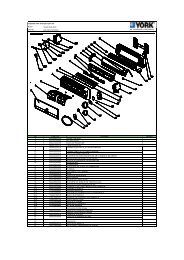
TABLE 1 – APPROXIMATE UNIT WEIGHT INCLUDING MOTOR - LBS (KGS)<br />
SHELLS<br />
COMPRESSOR<br />
SHIPPING<br />
WEIGHT<br />
Lbs (Kgs)<br />
OPERATING<br />
WEIGHT<br />
Lbs (Kgs)<br />
EST. REFRIGERANT<br />
CHARGE<br />
Lbs (Kgs)<br />
A-A Q3 13,100 (5,942) 15,000 (6,804) 810 (367)<br />
C-C Q3, Q4 14,920 (6,768) 17,940 (8,138) 1,240 (562)<br />
C-C Q5 15,330 (6,954) 18,350 (8,324) 1,240 (562)<br />
D-D Q3, Q4 17,215 (7,809) 21,100 (9,571) 1,680 (762)<br />
D-D Q5 17,625 (7,995) 21,510 (9,757) 1,680 (762)<br />
E-E Q3, Q4 17,950 (8,142) 22,160 (10,052) 1,710 (776)<br />
E-E Q5,Q6,Q7,P7 18,360 (8,328) 22,570 (10,238) 1,710 (776)<br />
F-F Q5,Q6,Q7,P7 18,720 (8,491) 23,880 (10,832) 2,175 (987)<br />
G-E P8 20,300 (9,208) 24,200 (10,977) 1,990 (903)<br />
H-F P8,P9 23,100 (10,478) 28,000 (12,701) 2,610 (1,184)<br />
J-J P8,P9 24,000 (10,886) 29,100 (13,200) 2,550 (1,157)<br />
L-L P8,P9 27,400 (12,429) 33,900 (15,377) 3,165 (1,436)<br />
K-K H9 28,530 (12,941) 36,000 (16,329) 2,925 (1,327)<br />
K-K K1 - - 2,925 (1,327)<br />
M-M H9 34,200(15,513) 43,600 (19,777) 3,665 (1,662)<br />
M-M K1,K2 38,300 (17,373) 47,100 (21,364) 3,665 (1,662)<br />
N-N K1,K2 28,530 (18,549) 50,800 (23,043) 4,225 (1,916)<br />
N-N K3 - - 4,225 (1,916)<br />
P-P K1,K2 41,500 (18,824) 51,900 (23,542) 3,855 (1,749)<br />
Q-Q K1,K2 45,300 (20,548) 56,800 (25,764) 4,255 (1,930)<br />
Q-Q K3 - - 4,255 (1,930)<br />
R-R K3 - - 4,660 (2,114)<br />
R-R K4 - - 4,785 (2,170)<br />
S-S K4 - - 4,940 (2,241)<br />
S-V K4 - - 5,500 (2,495)<br />
X-T K4 - - 5,125 (2,325)<br />
X-X K4 - - 5,625 (2,551)<br />
W-W K7 (37,467) (45,269) 6,900 (3,130)<br />
Z-Z K7 (36,968) (46,630) 6,275 (2,846)<br />
22<br />
JOHNSON CONTROLS
FORM 160.75-N1 (607)<br />
TABLE 2A – EVAPORATOR MARINE WATERBOX WEIGHTS - LBS (KGS)<br />
(To be added to standard unit weights shown in TABLE 1)<br />
SHIPPING WEIGHT<br />
OPERATING WEIGHT<br />
Evaporator<br />
INCREASE - Lbs (Kgs)<br />
INCREASE - Lbs (Kgs)<br />
Code<br />
1-Pass 2-Pass 3-Pass 1-Pass 2-Pass 3-Pass<br />
A<br />
924<br />
(419)<br />
744<br />
(337)<br />
978<br />
(444)<br />
1,468<br />
(666)<br />
1,288<br />
(584)<br />
1,522<br />
(690)<br />
C,D<br />
1,352<br />
(613)<br />
1,114<br />
(505)<br />
1,480<br />
(671)<br />
2,224<br />
(1,009)<br />
1,986<br />
(901)<br />
2,352<br />
(1,067)<br />
E,F<br />
1,878<br />
(852)<br />
1,260<br />
(572)<br />
2,080<br />
(943)<br />
3,378<br />
(1,532)<br />
2,760<br />
(1,252)<br />
3,580<br />
(1,624)<br />
G,H<br />
1,213<br />
550<br />
1,296<br />
(588)<br />
1,293<br />
(587)<br />
2,655<br />
(1,204)<br />
2,738<br />
(1,242)<br />
2,735<br />
(1,241)<br />
J,K,L<br />
1,751<br />
(794)<br />
1,843<br />
(836)<br />
1,856<br />
(842)<br />
3,864<br />
(1,753)<br />
3,956<br />
(1,794)<br />
3,969<br />
(1,800)<br />
M,N<br />
4,290<br />
(1,946)<br />
2,036<br />
(924)<br />
4,140<br />
(1,878)<br />
7,535<br />
(3,418)<br />
3,264<br />
(1,481)<br />
6,300<br />
(2,858)<br />
P,Q<br />
5,982<br />
(2,713)<br />
3,281<br />
(1,488)<br />
5,724<br />
(2,596)<br />
10,854<br />
(4,923)<br />
5,277<br />
(2,394)<br />
9,442<br />
(4,283)<br />
R,S,W - - - - - -<br />
X,Z - - - - - -<br />
TABLE 2B – CONDENSER MARINE WATERBOX WEIGHTS - LBS (KGS)<br />
(To be added to standard unit weights shown in TABLE 1)<br />
CONDENSER<br />
CODE<br />
A<br />
C,D<br />
E,F<br />
J,K,L<br />
M,N<br />
P,Q<br />
SHIPPING WEIGHT<br />
OPERATING WEIGHT<br />
INCREASE - Lbs (Kgs)<br />
INCREASE - Lbs (Kgs)<br />
1-Pass 2-Pass 3-Pass 1-Pass 2-Pass 3-Pass<br />
762<br />
566<br />
810<br />
1,274 1,078 1,322<br />
(346) (257) (367) (578) (489) (600)<br />
946<br />
(429)<br />
726<br />
(329)<br />
1,029<br />
(467)<br />
2,466<br />
(1,119)<br />
3,700<br />
(1,678)<br />
778<br />
(353)<br />
811<br />
(368)<br />
1,167<br />
(529)<br />
1,330<br />
(603)<br />
1,858<br />
(843)<br />
1,046<br />
(474)<br />
791<br />
(359)<br />
1,151<br />
(522)<br />
2,324<br />
(1,054)<br />
3,752<br />
(1,702)<br />
1,692<br />
(767)<br />
1,337<br />
(606)<br />
2,309<br />
(1,047)<br />
4,863<br />
(2,206)<br />
6,561<br />
(2,976)<br />
1,524<br />
(691)<br />
1,722<br />
(781)<br />
2,448<br />
(1,110)<br />
2,448<br />
(1,110)<br />
3,132<br />
(1,421)<br />
R,S - - - - - -<br />
V,T,W - - - - - -<br />
X,Z<br />
5,840<br />
(2,649)<br />
2,953<br />
(1,339)<br />
5,380<br />
(2,440)<br />
9,900<br />
(4,491)<br />
4,649<br />
(2,109)<br />
1,792<br />
(813)<br />
1,702<br />
(772)<br />
2,431<br />
(1,103)<br />
4,582<br />
(2,078)<br />
5,991<br />
(2,717)<br />
8,100<br />
(3,674)<br />
JOHNSON CONTROLS<br />
23
FORM 160.75-N1 (607)<br />
INTRODUCTION<br />
GENERAL<br />
This instruction describes the installation of a MODEL<br />
YK MaxE Liquid Chilling Unit. This unit is shipped<br />
as a single factory assembled, piped, wired package,<br />
requiring a minimum of field labor to make chilled water<br />
connections, condenser water connections, refrigerant<br />
atmospheric relief connections, and electrical power<br />
connections. (Refrigerant and oil charges shipped<br />
separately unless optional condenser isolation valves<br />
are ordered.)<br />
Chillers can also be shipped dismantled when required by<br />
rigging conditions, but generally it is more economical<br />
to enlarge access openings to accommodate the factory<br />
assembled unit. Chillers shipped dismantled MUST<br />
be field assembled under the supervision of a YORK<br />
representative, but otherwise installation will be as<br />
described in this instruction.<br />
FIELD ASSEMBLED UNITS <strong>ONLY</strong><br />
Use Form 160.73-N3 in conjunction with this installation<br />
instruction. This instruction will be furnished with all<br />
units that are to be field assembled.<br />
The services of a YORK representative will be furnished<br />
to check the installation, supervise the initial start-up<br />
and operation of all chillers installed within Continental<br />
United States.<br />
The YORK Warranty may be voided<br />
if the following restrictions are not<br />
adhered to:<br />
1. No valves or connections should be opened under<br />
any circumstances because such action will result<br />
in loss of the factory nitrogen charge.<br />
2. Do not dismantle or open the chiller for any<br />
reason except under the supervision of a YORK<br />
representative.<br />
3. When units are shipped dismantled, notify the<br />
nearest YORK office in ample time for a YORK<br />
representative to supervise rigging the unit<br />
to its operating position and the assembly of<br />
components.<br />
4. Do not make final power supply connections to the<br />
compressor motor or control center.<br />
5. Do not charge the compressor with oil.<br />
6. Do not charge the unit with refrigerant.<br />
7. Do not attempt to start the system.<br />
8. Do not run hot water (110°F / 43°C max) or steam<br />
through the evaporator or condenser at any time.<br />
SHIPMENT<br />
The chiller may be ordered and shipped in any of the<br />
following forms:<br />
Form 1 – Factory Assembled Unit, complete with<br />
motor, refrigerant and oil charges.<br />
1. The motor/compressor assembly mounted,<br />
with all necessary interconnecting piping<br />
assembled. OptiView Control Center is<br />
mounted on the unit. Complete unit factory<br />
leak tested, evacuated and charged with R-<br />
134A.<br />
An optional Solid State Starter or Variable<br />
Speed Drive can be factory mounted and<br />
wired.<br />
2. Miscellaneous material – Four (4)<br />
vibration isolation pads (or optional<br />
spring isolators and brackets).<br />
Form 2 – Factory Assembled Unit, complete with<br />
motor (refrigerant and oil charges shipped<br />
separately).<br />
1. The motor/compressor assembly mounted,<br />
with all necessary interconnecting piping<br />
assembled. OptiView Control Center is<br />
mounted on the unit. Complete unit factory<br />
leak tested, evacuated and charged with<br />
holding charge of nitrogen.<br />
An optional Solid State Starter or Variable<br />
Speed Drive can be factory mounted and<br />
wired.<br />
2. Miscellaneous material – Four (4)<br />
vibration isolation pads (or optional spring<br />
isolators).<br />
Form 3 – Driveline Separate From Shells – Shipped<br />
as two major assemblies. Unit first factory<br />
assembled, refrigerant piped, wired and<br />
leak tested; then dismantled for shipment.<br />
Compressor/motor assembly removed from<br />
shells and skidded. Evaporator/condenser is<br />
not skidded.<br />
24<br />
JOHNSON CONTROLS
FORM 160.75-N1 (607)<br />
JOHNSON CONTROLS<br />
All wiring integral with compressor is left on<br />
it, and all conduit is left on shell. All openings<br />
on compressor, oil separator, and shell are<br />
closed and charged with dry nitrogen (2 to 3<br />
PSIG) (115/122 kPa).<br />
Miscellaneous packaging of control center,<br />
tubing, water temperature controls, wiring,<br />
oil, isolators, solid state starter (option), etc.;<br />
refrigerant charge shipped separately.<br />
Units shipped dismantled MUST be reassembled<br />
by, or under the supervision<br />
of, a YORK representative. (See Form<br />
160.75-N3)<br />
Form 7 – Split Shells – Shipped as three major<br />
assemblies. Unit first factory assembled,<br />
refrigerant piped, wired and leak tested; then<br />
dismantled for shipment. Compressor/motor<br />
assembly removed from shells and skidded.<br />
Evaporator and condenser shells are separated<br />
at tube sheets and are not skidded. Refrigerant<br />
lines between shells are flanged and capped,<br />
requiring no welding.<br />
All wiring integral with compressor is left on<br />
it. All wiring harnesses on shells are removed.<br />
All openings on compressor and shells are<br />
closed and charged with dry nitrogen (2 to 3<br />
PSIG) (115/122 kPa).<br />
Miscellaneous packaging of control center,<br />
tubing, water temperature controls, wiring,<br />
oil isolators, solid state starter (option), etc.;<br />
refrigerant charge shipped separately.<br />
Units shipped dismantled MUST be reassembled<br />
by, or under the supervision<br />
of, a YORK representative. (See Form<br />
160.75-N3)<br />
When more than one chiller is involved, the major<br />
parts of each unit will be marked to prevent mixing of<br />
assemblies. (Piping and Wiring Drawings to be furnished<br />
by YORK.)<br />
INSPECTION – DAMAGE – SHORTAGE<br />
The unit shipment should be checked on arrival to see<br />
that all major pieces, boxes and crates are received. Each<br />
unit should be checked on the trailer or rail car when<br />
received, before unloading, for any visible signs of<br />
damage. Any damage or signs of possible damage must<br />
be reported to the transportation company immediately<br />
for their inspection.<br />
YORK WILL NOT BE RESPONSIBLE FOR ANY<br />
DAMAGE IN SHIPMENT OR AT JOB SITE OR<br />
LOSS OF PARTS. (Refer to Shipping Damage Claims,<br />
Form 50.15-NM)<br />
When received at the job site all containers should be<br />
opened and contents checked against the packing list.<br />
Any material shortage should be reported to YORK<br />
immediately. (Refer to Shipping Damage Claims, Form<br />
50.15-NM)<br />
CHILLER DATA PLATE<br />
A unit data plate is mounted on the control center<br />
assembly of each unit, giving unit model number; design<br />
working pressure; water passes; refrigerant charge;<br />
serial numbers; and motor power characteristics and<br />
connection diagrams.<br />
Additional information may be found on the motor<br />
data plate. This information should be included when<br />
contacting the factory on any problem relating to the<br />
motor.<br />
RIGGING (See FIG. 17)<br />
The complete standard chiller is shipped without skids.<br />
(When optional skids are used it may be necessary to<br />
remove the skids so riggers skates can be used under the<br />
unit end sheets to reduce overall height.)<br />
Each unit has four (4) lifting holes (two in each end) in<br />
the end sheets which should be used to lift the unit.<br />
Care should be taken at all times during rigging and<br />
handling of the chiller to avoid damage to the unit and<br />
its external connections. Lift only using holes shown<br />
in FIG. 17.<br />
Do NOT lift the unit with slings around<br />
motor/compressor assembly or by<br />
means of eyebolts in the tapped holes<br />
of the compressor motor assembly. Do<br />
NOT turn a unit on its side for rigging.<br />
Do NOT rig vertically.<br />
25
FORM 160.75-N1 (607)<br />
LD00700(R)<br />
FIG. 17 – RIGGING<br />
The rigging and operating weights and overall<br />
dimensions are given on pages 6 thru 11 as a guide in<br />
determining the clearances required for rigging. Add 6"<br />
(15 cm) to overall height for optional skidded unit.<br />
LOCATION<br />
YORK MaxE Chillers are furnished with vibration<br />
isolator mounts for basement or ground level installations.<br />
Units may be located on upper floor levels providing the<br />
floor is capable of supporting the total unit operating<br />
weight and optional spring isolators are used.<br />
26<br />
Sufficient clearance to facilitate<br />
normal service and maintenance<br />
work must be provided all around<br />
and above the unit and particularly<br />
space provided at either end to<br />
permit cleaning or replacement of<br />
evaporator and condenser tubes<br />
– see CLEARANCE. A doorway<br />
or other sufficiently large opening<br />
properly located may be used. The<br />
MOTORS<br />
chiller should be located in an indoor<br />
location where temperatures range<br />
from 40°F to 110°F (4.4°C to 43.3°C).<br />
The YK open motor is air cooled. Check state, local and<br />
other codes for ventilation requirements.<br />
FOUNDATION<br />
A level floor, mounting pad or foundation must be<br />
provided by others, capable of supporting the operating<br />
weight of the unit.<br />
CLEARANCE<br />
Clearances should be adhered to as follows:<br />
Rear and above unit – 2 ft (61 cm).<br />
Front of unit – 3 ft (91 cm).<br />
Tube Removal – 14 ft.* (4.3 m) (either end)<br />
* 16 ft (4.9 meters) on shell codes Q-Q, N-N, R-R, X-T & X-X.<br />
** 18 ft (5.5 meters) on shell code S-S, S-V, Z-Z.<br />
*** 22 ft (6.7 meters) on shell code W-W.<br />
JOHNSON CONTROLS
FORM 160.75-N1 (607)<br />
ALL DIMENSIONS ARE IN INCHES (MM)<br />
LD12638<br />
LD12639<br />
UNIT WEIGHT UP TO 16,365 Lbs (7,423 Kgs)<br />
UNIT WEIGHT 16,366 - 28,835 Lbs (7,424 - 13,080 Kgs)<br />
LD12640<br />
LD12641<br />
UNIT WEIGHT 28,836 - 53,530 Lbs (13,081 - 24,281 Kgs)<br />
UNIT WEIGHT 53,531 - 100,464 Lbs (45,570 - 58,968 Kgs)<br />
LD12642<br />
UNIT WEIGHT 100,465 - 130,000 Lbs (45,570 - 58,967 Kgs)<br />
FIG. 18 – NEOPRENE ISOLATORS<br />
JOHNSON CONTROLS<br />
27
FORM 160.75-N1 (607)<br />
ALL DIMENSIONS ARE IN INCHES (MM)<br />
LD12643<br />
UNIT WEIGHT DIM "A" DIM "B" DIM "C" DIM "D"<br />
Up To 16,365 Lbs<br />
(7,423 Kgs)<br />
16,366 - 28,835 Lbs<br />
(7,424 - 13,08 Kgs)<br />
28,836 - 53,530 Lbs<br />
(13,081 - 24,281 Kgs)<br />
53,531 - 100,464 Lbs<br />
(24,281 - 45,569 Kgs)<br />
100,465 - 130,000 Lbs<br />
(45,570 - 58,967 Kgs)<br />
FIG. 19 – NEOPRENE ISOLATORS<br />
See FIG's 2-7 See FIG's 2-7<br />
See FIG's 2-7 See FIG's 2-7<br />
See FIG's 2-7 See FIG's 2-7<br />
See FIG's 2-7 See FIG's 2-7<br />
See FIG's 2-7 See FIG's 2-7<br />
6"<br />
(152mm)<br />
6"<br />
(152mm)<br />
6"<br />
(152mm)<br />
10"<br />
(254mm)<br />
10"<br />
(254mm)<br />
8"<br />
(203mm)<br />
8"<br />
(203mm)<br />
8"<br />
(203mm)<br />
8"<br />
(203mm)<br />
8"<br />
(203mm)<br />
28<br />
JOHNSON CONTROLS
FORM 160.75-N1 (607)<br />
ALL DIMENSIONS ARE IN INCHES (MM)<br />
LD126544<br />
LD12645<br />
UNIT WEIGHT<br />
10,000 Lbs UP TO 35,009 Lbs<br />
(4,536 Kgs UP TO 15,880 Kgs)<br />
UNIT WEIGHT<br />
35,010 Lbs UP TO 58,349 Lbs<br />
(15,881 Kgs UP TO 26,467 Kgs)<br />
LD12646<br />
LD12647<br />
UNIT WEIGHT<br />
89,341 Lbs UP TO 115,000 Lbs<br />
(40,252 Kgs UP TO 52,164 Kgs)<br />
UNIT WEIGHT<br />
115,000 Lbs. UP TO 190,000 Lbs<br />
(52,163 Kgs UP TO 86,182 Kgs)<br />
FIG. 20 – SPRING ISOLATORS<br />
JOHNSON CONTROLS<br />
29
FORM 160.75-N1 (607)<br />
ALL DIMENSIONS ARE IN INCHES (MM)<br />
LD12643a<br />
UNIT WEIGHT DIM "A" DIM "B" DIM "C" DIM "D" DIM "E"<br />
10,000 - 35,009 Lbs<br />
(4,536 - 15,880 Kgs)<br />
35,010 - 58,349 Lbs<br />
(15,881 - 26,467 Kgs)<br />
89,341 - 115,000 Lbs<br />
(40,252 - 52,164 Kgs)<br />
115,000 - 190,000 Lbs<br />
(52,163 - 86,182 Kgs)<br />
See<br />
FIG's 2-7<br />
See<br />
FIG's 2-7<br />
See<br />
FIG's 2-7<br />
See<br />
FIG's 2-7<br />
See<br />
FIG's 2-7<br />
See<br />
FIG's 2-7<br />
See<br />
FIG's 2-7<br />
See<br />
FIG's 2-7<br />
6"<br />
(152)<br />
9"<br />
(229)<br />
13-1/2"<br />
(343)<br />
16"<br />
(406)<br />
6-7/8"<br />
(175)<br />
7"<br />
(178)<br />
8"<br />
(203)<br />
17"<br />
(432)<br />
5-1/2"<br />
(140)<br />
6-1/4"<br />
(159)<br />
5"<br />
(127)<br />
16-1/4"<br />
(413)<br />
FIG. 21 – SPRING ISOLATORS<br />
30<br />
JOHNSON CONTROLS
FORM 160.75-N1 (607)<br />
RIGGING UNIT TO FINAL LOCATION<br />
Rig the unit to its final location on the floor or mounting<br />
pad, lift the unit (or shell assembly) by means of an<br />
overhead lift and lower the unit to its mounting position.<br />
(If optional shipping skids are used, remove them before<br />
lowering the chiller to its mounting position.)<br />
At this point units shipped dismantled<br />
should be assembled under the supervision<br />
of a YORK representative.<br />
INSTALLATION<br />
INSTALLING OPTIONAL SPRING ISOLATORS<br />
(REFER TO FIG. 20 OR 21)<br />
When ordered, spring type isolator assemblies will be<br />
furnished with the unit. The 4 assemblies are identical<br />
and can be placed at any of the 4 corners of the unit.<br />
While the unit is still suspended by the rigging, the<br />
isolators should be bolted to the unit by inserting the<br />
cap screw(s) through the hole(s) in the mounting bracket<br />
into the tapped hole in the top of the isolator leveling<br />
bolt(s). Then the unit can be lowered onto the floor.<br />
If evaporator is to be field insulated, the insulation should<br />
be applied to the evaporator before the unit is placed in<br />
position while the unit is in the lift position. Be sure unit<br />
is properly supported. (See INSULATION, page 27)<br />
LOCATING AND INSTALLING ISOLATOR PADS<br />
(REFER TO FIG. 18 OR 19)<br />
The isolator pad mounts are to be located as shown in<br />
FIG. 18 or 19 ( Rubber side down).<br />
After the isolator pads have been placed into position on<br />
the floor, lower the chiller onto the pads. When the unit<br />
is in place, remove the rigging equipment and check that<br />
the unit is level. The unit should be level within 1/4"<br />
(6 mm) from one end to the other end and from front<br />
to the rear. If the chiller is not level within the amount<br />
specified, lift it and place shims between the isolation<br />
pad and the chiller tube sheets. (Shims furnished by<br />
the installer.) Lower unit again and recheck to see that<br />
it is level.<br />
CHECKING THE ISOLATION PAD DEFLECTION<br />
All isolation pads should be checked for the proper<br />
deflection while checking to see if the unit is level. Each<br />
pad should be deflected approximately 0.10 inches (2.5<br />
mm) to 0.20 inches (5 mm). If an isolation pad is underdeflected,<br />
shims should be placed between the unit tube<br />
sheet and the top of the pad to equally deflect all pads.<br />
LEVELING THE UNIT<br />
The longitudinal alignment of the unit should be checked<br />
by placing a level on the top center of the evaporator<br />
shell under the compressor/motor assembly. Transverse<br />
alignment should be checked by placing a level on top<br />
of the shell end sheets.<br />
JOHNSON CONTROLS<br />
The leveling bolts should now be rotated one (1) turn at<br />
a time, in sequence, until the unit end sheets are clear<br />
of the floor by the dimension shown in FIG. 19 or 21<br />
and the unit is level. Check that the unit is level, both<br />
longitudinally and transversely (see Leveling the Unit).<br />
If the leveling bolts are not long enough to level unit<br />
due to an uneven or sloping floor or foundation, steel<br />
shims (grouted, if necessary) must be added beneath the<br />
isolator assemblies as necessary.<br />
After the unit is leveled, wedge and shim under each<br />
corner to solidly support the unit in this position while<br />
piping connections are being made, pipe hangers adjusted<br />
and connections checked for alignment. Then the unit is<br />
filled with water and checked for leaks. The leveling bolts<br />
should now be finally adjusted until the wedges and shims<br />
can be removed. The unit should now be in correct level<br />
position, clear of the floor or foundation and without any<br />
effect from the weight of the piping.<br />
PIPING CONNECTIONS<br />
After the unit is leveled (and wedged in place for optional<br />
spring isolators) the piping connections may be made;<br />
chilled water, condenser water and refrigerant relief. The<br />
piping should be arranged with offsets for flexibility, and<br />
adequately supported and braced independently of the<br />
unit to avoid strain on the unit and vibration transmission.<br />
Hangers must allow for alignment of pipe. Isolators (by<br />
others) in the piping and hangers are highly desirable,<br />
and may be required by specifications, in order to<br />
effectively utilize the vibration isolation characteristics<br />
of the vibration isolation mounts of the unit.<br />
Check for piping alignment – Upon completion of<br />
piping, a connection in each line as close to the unit as<br />
possible should be opened, by removing the flange bolts<br />
or coupling and checked for piping alignment. If any of<br />
the bolts are bound in their holes, or if the connection<br />
springs are out of alignment, the misalignment must<br />
31
FORM 160.75-N1 (607)<br />
be corrected by properly supporting the piping or by<br />
applying heat to anneal the pipe.<br />
If the piping is annealed to relieve<br />
stress, the inside of the pipe must be<br />
cleaned of scale before it is finally<br />
bolted in place.<br />
EVAPORATOR AND CONDENSER WATER PIPING<br />
The evaporator and condenser liquid heads of chiller<br />
have nozzles which are grooved, suitable for welding<br />
150 PSIG DWP flanges or the use of flexible couplings.<br />
Factory mounted flanges are optional.<br />
The nozzles and water pass arrangements are furnished<br />
in accordance with the job requirements (see Product<br />
Drawings) furnished with the job. Standard units are<br />
designed for 150 PSIG DWP on the water side. If job<br />
requirements are for greater than 150 PSIG DWP, check<br />
the unit data plate before applying pressure to evaporator<br />
or condenser to determine if the chiller has provisions<br />
for the required DWP.<br />
Inlet and outlet connections are identified by labels<br />
placed adjacent to each nozzle.<br />
Chilled Water<br />
Foreign objects which could lodge in, or block flow<br />
through, the evaporator and condenser tubes must be<br />
kept out of the water circuit. All water piping must be<br />
cleaned or flushed before being connected to the chiller<br />
pumps, or other equipment.<br />
Permanent strainers (supplied by others) are required<br />
in both the evaporator and condenser water circuits to<br />
protect the chiller as well as the pumps, tower spray<br />
nozzles, chilled water coils and controls, etc. The<br />
strainer must be installed in the entering chilled water<br />
line, directly upstream of the chiller.<br />
Water piping circuits should be arranged so that the<br />
pumps discharge through the chiller, and should be<br />
controlled as necessary to maintain essentially constant<br />
chilled and condenser water flows through the unit at<br />
all load conditions.<br />
If pumps discharge through the chiller, the strainer may<br />
be located upstream from pumps to protect both pump<br />
and chiller. (Piping between strainer, pump and chiller<br />
must be very carefully cleaned before start-up.) If pumps<br />
are remotely installed from chiller, strainers should be<br />
located directly upstream of the chiller.<br />
Condenser Water Circuit<br />
For proper operation of the unit, condenser refrigerant<br />
pressure must be maintained above evaporator pressure.<br />
If operating conditions will fulfill this requirement, no<br />
attempt should be made to control condenser water<br />
temperature by means of automatic valves, cycling of<br />
the cooling tower fan or other means, since chillers are<br />
designed to function satisfactorily and efficiently when<br />
condenser water is allowed to seek its own temperature<br />
level at reduced loads and off-peak seasons of the year.<br />
However, if entering condenser water temperature can<br />
go below the required minimum, (refer to 160.75-O1)<br />
condenser water temperature must be maintained equal<br />
to or slightly higher than the required minimum. Refer<br />
to FIG. 22 for typical water piping schematic.<br />
EVAPORATOR<br />
FIG. 22 – SCHEMATIC OF A TYPICAL PIPING ARRANGEMENT<br />
32<br />
LD08529<br />
JOHNSON CONTROLS
FORM 160.75-N1 (607)<br />
VENT TO ATMOSPHERE<br />
FLANGED JOINT<br />
TO PERMIT PIPING<br />
DISASSEMBLY<br />
SUPPORT VENT PIPING TO AVOID<br />
STRAIN ON RELIEF PIPING<br />
FLEXIBLE CONNECTOR<br />
CONDENSATION<br />
TRAP<br />
DUAL RELIEF<br />
VALVES<br />
CONDENSER<br />
COOLER<br />
SEE NOTE<br />
EVAPORATOR<br />
FIG. 23 – TYPICIAL REFRIGERANT VENT PIPING<br />
NOTE: SHELLS MAY BE FURNISHED WITH<br />
ONE OR TWO RELIEF VALVES,<br />
DEPENDING ON SHELL SIZE.<br />
LD03863<br />
Stop Valves<br />
Stop valves may be provided (by others) in the<br />
evaporator and condenser water piping adjacent to the<br />
unit to facilitate maintenance. Thermometer wells and<br />
pressure taps should be provided (by others) in the piping<br />
as close to the unit as possible to facilitate operating<br />
check.<br />
Flow Switches<br />
Thermal type water flow switches are factory mounted in<br />
the chilled and condensed water nozzles and are factory<br />
wired to the OptiView control panel. These solid-state<br />
flow sensors have a small internal heating element and<br />
use the cooling effect of the flowing fluid to sense when<br />
an adequate flow rate has been established.<br />
Waterbox Drain and Vent Valves<br />
Drain and vent valves (by others) should be installed<br />
in the connections provided in the evaporator and<br />
condenser liquid heads. These connections may be<br />
piped to drain if desired.<br />
Checking Piping Circuits and Venting Air<br />
After the water piping is completed, but before any water<br />
box insulation is applied. Tighten and torque to maintain<br />
between 30 and 60 ft. lbs. (41 and 81 N·m) the nuts on<br />
the liquid head flanges. Gasket shrinkage and handling<br />
during transit cause nuts to loosen. If water pressure is<br />
applied before tightening is done, the gaskets may be<br />
damaged and have to be replaced. Fill the chilled and<br />
condenser water circuits, operate the pumps manually<br />
JOHNSON CONTROLS<br />
and carefully check the evaporator and condenser water<br />
heads and piping for leaks. Repair leaks as necessary.<br />
Before initial operation of the unit both water circuits<br />
should be thoroughly vented of all air at the high<br />
points.<br />
REFRIGERANT RELIEF PIPING<br />
Each unit is equipped with pressure relief valves located<br />
on the condenser and on the evaporator for the purpose<br />
of quickly relieving excess pressure of the refrigerant<br />
charge to the atmosphere as a safety precaution in case<br />
of an emergency, such as fire.<br />
Refrigerant relief vent piping (by others), from the relief<br />
valves to the outside of the building, is required by code<br />
in most areas and should be installed on all chillers. The<br />
vent line should be sized in accordance with the ANSI/<br />
ASHRAE-15, or local code. The vent line must include<br />
a dirt trap in the vertical leg to intercept and permit clean<br />
out and to trap any vent stack condensation. The piping<br />
MUST be arranged to avoid strain on the relief valves,<br />
using a flexible connection, if necessary.<br />
UNIT PIPING<br />
Compressor lubricant piping and system external piping<br />
are factory installed on all units shipped assembled. On<br />
units shipped dismantled, the following piping should<br />
be completed under the supervision of the YORK<br />
representative: (1) the lubricant piping to oil sump and<br />
oil evaporator and system oil return connections using<br />
material furnished. See Form 160.75-N3.<br />
33
FORM 160.75-N1 (607)<br />
CONTROL PANEL POSITIONING (See FIG. 24)<br />
On large YK chillers, the control panel height can be<br />
adjusted. The OptiView Control Center is placed in<br />
a position above the evaporator for shipping. To move<br />
the control center into position for operation, proceed<br />
as follows:<br />
1. While supporting the control center, remove<br />
the hardware between the support arms and the<br />
evaporator.<br />
2. Swing the control center into a vertical position.<br />
3. Slide the control center down the guide rails to the<br />
proper position. Tighten securely.<br />
4. Discard unused hardware.<br />
SUPPORT<br />
ARMS<br />
PANEL<br />
TRACK<br />
FIG. 24 – CONTROL PANEL POSITIONING<br />
LD03826<br />
CONTROL WIRING<br />
On units shipped disassembled, after installation of<br />
the control center, control wiring must be completed<br />
between unit components and control center, solid state<br />
starter, or variable speed drive, when used, using wiring<br />
harness furnished. Refer to Form 160.75-N3.<br />
Field wiring connections for commonly encountered<br />
control modifications (by others) if required, are shown<br />
on Form 160.75-PW4.<br />
POWER WIRING<br />
No deviations in unit wiring from that<br />
shown on drawings furnished shall<br />
be made without prior approval of the<br />
YORK representative.<br />
Chiller with Electro-Mechanical Starter<br />
A 115 volt – single phase – 60 or 50 Hertz power supply<br />
of 20 amperes must be furnished to the control center,<br />
from the control transformer (2 KVA required) included<br />
with the compressor motor starter. Do NOT make final<br />
power connections to control center until approved by<br />
YORK representative.<br />
OIL PUMP – 3 PHASE STARTER<br />
Separate wiring or a fused disconnect switch should be<br />
supplied by the installer.<br />
Remote Electro-Mechanical starters<br />
for the chiller must be furnished in accordance<br />
with YORK Starter Specifications<br />
Product Drawing Form 160.73-<br />
PA1 to provide the features necessary<br />
for the starter to function properly with<br />
the YORK control system.<br />
Each chiller unit is furnished for a specific electrical<br />
power supply as stamped on the Unit Data Plate, which<br />
also details the motor connection diagrams.<br />
To insure proper motor rotation the<br />
starter power input and starter to motor<br />
connections must be checked with<br />
a phase sequence indicator in the presence<br />
of the YORK representative.<br />
DO NOT cut wires to final length<br />
or make final connections to motor<br />
terminals or starter power input terminals<br />
until approved by the YORK<br />
representative.<br />
YK Motors (Electro-Mechanical Starter)<br />
Motor leads are furnished with a crimp type connection<br />
having a clearance hole for a 3/8" bolt, motor terminal<br />
lugs are not furnished. Refer to Wiring Labels in motor<br />
terminal box for hook-up to suit motor voltage and<br />
amperage for power wiring connections.<br />
34<br />
JOHNSON CONTROLS
FORM 160.75-N1 (607)<br />
Chiller with Solid State Starter or<br />
Variable Speed Drive<br />
A chiller equipped with a factory mounted Solid State<br />
Starter or Variable Speed Drive does not require wiring<br />
to the compressor motor. The motor power wiring is<br />
factory connected to the Solid State Starter or Variable<br />
Speed Drive (or an optional factory installed disconnect<br />
switch). See Field Wiring Diagram. All wiring to the<br />
control panel and the oil pump starter is completed by<br />
the factory. A control transformer is furnished with the<br />
Solid State Starter or Variable Speed Drive.<br />
INSULATION<br />
(See FIG. 25)<br />
DO NOT field insulate until the unit has<br />
been leak tested under the supervision<br />
of the YORK representative.<br />
Insulation of the type specified for the job, or minimum<br />
thickness to prevent sweating of 30°F (-1°C) surfaces<br />
should be furnished (by others) and applied to the<br />
evaporator shell, end sheets, liquid feed line to flow<br />
chamber, compressor suction connection, and evaporator<br />
liquid heads and connections. The liquid head flange<br />
insulation must be removable, to allow head removal for<br />
the tube maintenance. Details of areas to be insulated<br />
are given on the Product Drawing.<br />
Units are furnished factory anti-sweat insulated on order<br />
at additional cost. This includes all low temperature<br />
surfaces except the two (2) cooler liquid heads.<br />
INSTALLATION CHECK –<br />
REQUEST FOR START-UP SERVICE<br />
The services of a YORK representative will be furnished<br />
to check the installation and supervise the initial startup<br />
and operation on all chillers installed within the<br />
Continental United States.<br />
After the unit is installed, piped and wired as described<br />
in this Instruction, but before any attempt is made to start<br />
the unit, the YORK District Office should be advised<br />
so that the start-up service, included in the contract<br />
price, can be scheduled. Notification to the YORK<br />
office should be by means of Installation Checklist and<br />
Request, Form 160.46-CL1, in triplicate.<br />
LD12649<br />
FIG. 25 – UNIT INSULATION<br />
JOHNSON CONTROLS<br />
35
P.O. Box 1592, York, Pennsylvania USA 17405-1592<br />
Copyright © by <strong>Johnson</strong> <strong>Controls</strong> 2007<br />
Form 160.75-N1 (607)<br />
Supersedes: NOTHING<br />
Tele. 800-861-1001<br />
www.york.com<br />
Subject to change without notice. Printed in USA<br />
ALL RIGHTS RESERVED
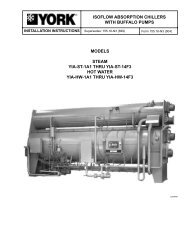


![[PDF] Catálogo Técnico YP Corrigido Corel 9 - Johnson Controls](https://img.yumpu.com/49244478/1/190x245/pdf-catalogo-taccnico-yp-corrigido-corel-9-johnson-controls.jpg?quality=85)