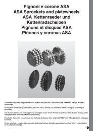
Ramsey Duplex Silent Chains
Ramsey Duplex Silent Chains
Ramsey Duplex Silent Chains

Create successful ePaper yourself
Turn your PDF publications into a flip-book with our unique Google optimized e-Paper software.
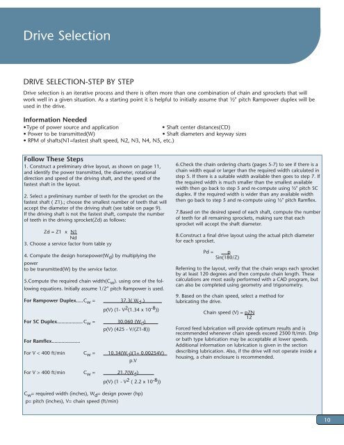
Drive Selection<br />
DRIVE SELECTION-STEP BY STEP<br />
Drive selection is an iterative process and there is often more than one combination of chain and sprockets that will<br />
work well in a given situation. As a starting point it is helpful to initially assume that ½" pitch Rampower duplex will be<br />
used in the drive.<br />
Information Needed<br />
• Type of power source and application<br />
• Shaft center distances(CD)<br />
• Power to be transmitted(W)<br />
• Shaft diameters and keyway sizes<br />
• RPM of shafts(N1=fastest shaft speed, N2, N3, N4, N5, etc.)<br />
Follow These Steps<br />
1. Construct a preliminary drive layout, as shown on page 11,<br />
and identify the power transmitted, the diameter, rotational<br />
direction and speed of the driving shaft, and the speed of the<br />
fastest shaft in the layout.<br />
2. Select a preliminary number of teeth for the sprocket on the<br />
fastest shaft ( Z1).; choose the smallest number of teeth that will<br />
accept the diameter of the driving shaft (see table on page 9).<br />
If the driving shaft is not the fastest shaft, compute the number<br />
of teeth in the driving sprocket(Zd) as follows:<br />
Zd = Z1 x N1<br />
Nd<br />
3. Choose a service factor from table yy<br />
4. Compute the design horsepower(W d ) by multiplying the<br />
power<br />
to be transmitted(W) by the service factor.<br />
5.Compute the required chain width(C w ). using one of the following<br />
equations. Initially assume 1/2” pitch Rampower is used.<br />
For Rampower <strong>Duplex</strong>.....C w = 37.3( W d )<br />
p(V) (1- V 2 (1.34 x 10 -8 ))<br />
For SC <strong>Duplex</strong>.................. C w = 30,060 (W d )<br />
For Ramflex....................<br />
p(V) (425 - V/(Z1-8))<br />
For V < 400 ft/min C w = 10.34(W d )(1+ 0.00254V)<br />
p.V<br />
6.Check the chain ordering charts (pages 5-7) to see if there is a<br />
chain width equal or larger than the required width calculated in<br />
step 5. If there is a suitable width available then goes to step 7. If<br />
the required width is much smaller than the smallest available<br />
width then go back to step 5 and re-compute using ½" pitch SC<br />
duplex. If the required width is wider than any available width<br />
then go back to step 5 and re-compute using ½" pitch Ramflex.<br />
7.Based on the desired speed of each shaft, compute the number<br />
of teeth for all remaining sprockets, making sure that each<br />
sprocket will accept the shaft diameter.<br />
8.Construct a final drive layout using the actual pitch diameter<br />
for each sprocket.<br />
Pd =<br />
p<br />
Sin(180/Z)<br />
Referring to the layout, verify that the chain wraps each sprocket<br />
by at least 120 degrees and then compute chain length. These<br />
calculations are most easily performed with a CAD program, but<br />
can also be completed using geometry and trigonometry.<br />
9. Based on the chain speed, select a method for<br />
lubricating the drive.<br />
Chain speed (V) = pZN<br />
12<br />
Forced feed lubrication will provide optimum results and is<br />
recommended whenever chain speeds exceed 2500 ft/min. Drip<br />
or bath type lubrication may be acceptable at lower speeds.<br />
Additional information on lubrication is given in the section<br />
describing lubrication. Also, if the drive will not operate inside a<br />
housing, a chain enclosure is recommended.<br />
For V > 400 ft/min C w = 21.7(W d )<br />
p(V) (1 - V 2 ( 2.2 x 10 -8 ))<br />
C w = required width (inches), W d = design power (hp)<br />
p= pitch (inches), V= chain speed (ft/min)<br />
10