DESCH Conax®-Clutches - TB Hengelo
DESCH Conax®-Clutches - TB Hengelo
DESCH Conax®-Clutches - TB Hengelo

You also want an ePaper? Increase the reach of your titles
YUMPU automatically turns print PDFs into web optimized ePapers that Google loves.
w h e n f u l l p o w e r i s n e e d e d<br />
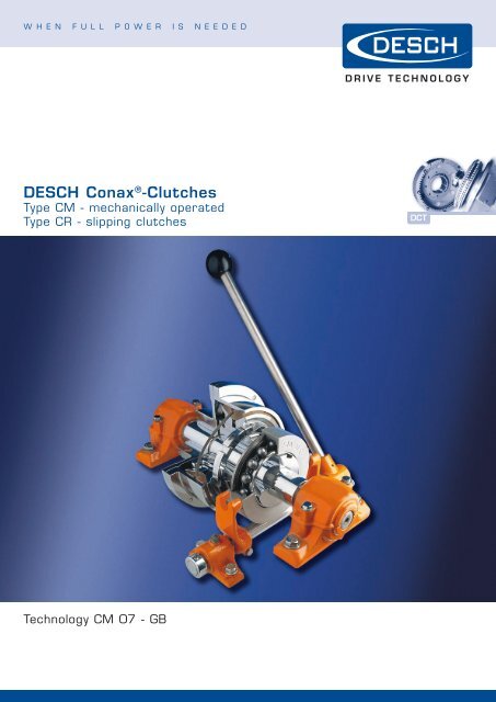
<strong>DESCH</strong> Conax ® -<strong>Clutches</strong><br />
Type CM - mechanically operated<br />
Type CR - slipping clutches<br />
Technology CM 07 - GB
w h e n f u l l p o w e r i s n e e d e d<br />
Conax ® -Friction <strong>Clutches</strong><br />
<br />
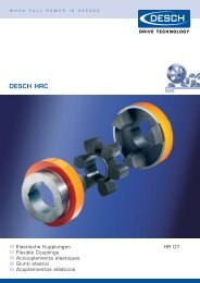
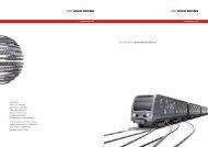
Fig. 1 Conax ® -Friction Clutch<br />
Type CM<br />
Conax ® - Friction Clutch Type CM<br />
The characteristic feature of the Conax ® -<br />
clutch is the expanding symmetrical<br />
friction ring* between the cone-shaped<br />
metal discs. It is divided into six segments<br />
which are held together by a<br />
tension spring. Axial displacements of<br />
the shafts are offset in the bore of the<br />
casing when the clutch is disengaged.<br />
The contact forces in the system cancel<br />
each other out, there is no axial loading<br />
of the machine bearings when the clutch<br />
is engaged.<br />
Operation of the Conax ® -Friction<br />
Clutch<br />
When the clutch is being engaged, the<br />
sleeve and the deepgroove bearing (17)<br />
slide over the clutch levers (5). They<br />
press the metal disc (7) against the friction<br />
ring* (9) which, as a result, slides<br />
outwards evenly until it forms a friction<br />
connection with the clutch casing (1)<br />
and the flanks of the metal discs (7)<br />
and (11). When the clutch is being disengaged,<br />
the sleeve and the deepgroove<br />
bearing (17) release the clutch levers (5).<br />
The pressure springs (8) press the metal<br />
discs (7 and 11) apart and the friction<br />
ring* segments are pulled inwards by<br />
the tension spring (10). As a result the<br />
clutch section is completely detached<br />
from the casing (1). The clutch is set<br />
and re-adjusted by tightening the adjusting<br />
ring (12), which is secured against<br />
turning by the locking screw (19). The<br />
segments of the friction ring* are held<br />
together by the tension spring up to the<br />
speed n F<br />
. The tensile force of the spring<br />
is greater than the centrifugal force of<br />
the segments. In order to avoid a residual<br />
torque when the clutch is disengaged,<br />
the speed must be reduced to below n F<br />
during or shortly after the disengaging<br />
operation (see table, page 4). The clutch<br />
casing is preferably arranged on the<br />
input side. When the clutch hub is located<br />
on the input side, a friction ring*<br />
with an internal spring has to be used<br />
if the speed n F<br />
is exceeded. In this case<br />
the friction ring* is in contact with the<br />
clutch casing.<br />
* The friction rings are asbestos-free<br />
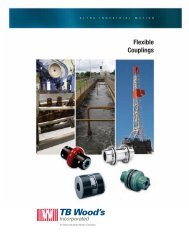
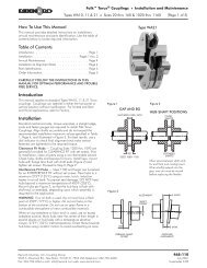
Fig. 2 Conax ® -Slipping Clutch<br />
Type CR<br />
Conax ® -Slipping Clutch Type CR<br />
The Conax ® -slipping clutch type CR is<br />
designed to protect machine components<br />
against desctruction in the event of<br />
overloading or blocking of the driven<br />
machine. The Conax ® -slipping clutches<br />
are manufactured in two basic designs,<br />
depending on the size. The sizes 0,5 to<br />
25 are adjusted with a threaded ring.<br />
For this purpose the sizes 50 to 200 are<br />
provided with disc spring assemblies.<br />
Accurate setting of the torque is possible<br />
with both designs. The required<br />
contact pressure on the friction ring*<br />
(9) is produced by means of the adjusting<br />
ring (11) or hexagon nut (17),<br />
disc spring (14 or 16) and metal disc<br />
(7) and the torque is transmitted by<br />
friction. The disc springs (14,16) offset<br />
wear over a relatively long path, thus<br />
reducing maintenance to a minimum.<br />
The clutch is to be set so that it slips<br />
when peak loads occur. If a prolonged<br />
slipping timer can occur as a result of<br />
the machines blocking, it is advisable<br />
to provide a monitoring system as per<br />
Figs. 21 and 22 (page 10).<br />
Types<br />
CM. - Conax ® mech. actuated<br />
CR. - Conax ® -slipping clutch<br />
C. F. - Flange to shaft connection<br />
C.W. - Shaft to shaft connection<br />
• Low maintenance, operation-safe,<br />
reliable<br />
• asbestos-free friction material<br />
with long life-time<br />
• high heat capacity<br />
• approved design
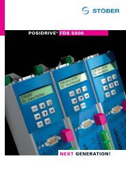
Parts of the Conax ® -Friction Clutch<br />
Type CM<br />
Fig. 3 Size 1 - 16<br />
(with bearing)<br />
1 Casing<br />
2 Socket head screw<br />
3 Flanged hub<br />
4 Bolt<br />
5 Cluch Level<br />
6 Key<br />
7 Cone disc<br />
8 Spring (not in size 1)<br />
9 Friction ring: Tension spring type<br />
Friction ring: Inner spring ring<br />
10 Tension spring, Inner spring<br />
11 Cone disc<br />
12 Adjusting ring<br />
13 Set screw<br />
14 Stop (Key)<br />
15 Circlip (Stop ring)<br />
16 Clutch hub<br />
17 Ball bearing (Coupling sleeve)<br />
18 Operation ring (Slip ring)<br />
Fig. 4 Size 25 - 50<br />
(with slip ring)<br />
19 Socket head screw<br />
21 Ring (Size 8, 16)<br />
22 Retaining ring<br />
(Hexagon head srew with nut)<br />
23 (Grease nipple)<br />
24 (Split pin)<br />
25 Collar<br />
29 Set srew<br />
The designations in brackets are valid<br />
for slip ring operation (size 25 – 50)<br />
Parts of the Conax ® -Slipping Clutch<br />
Type CR<br />
1 Casing<br />
2 Socket head sceaw<br />
3 Flanged hub<br />
4 Clutch hub<br />
6 Key (Key pin size 0,5)<br />
7 Cone disc<br />
8 Set screw<br />
9 Friction ring<br />
10 Tension spring (Circlip size 0,5)<br />
11 Adjusting ring<br />
12 Set screw<br />
13 Thrust pad<br />
14 Plate pad<br />
15 Fitting bolt<br />
16 Plate spring<br />
17 Hexagon nut<br />
18 Adjustment plate<br />
29 Set screw<br />
Fig. 5
w h e n f u l l p o w e r i s n e e d e d<br />
Conax ® -Friction <strong>Clutches</strong><br />
Fig. 6 Type CMW<br />
Size 1 - 16<br />
Dimensions in mm • Can be delivered ex stock<br />
Fig. 7 Type CMF<br />
Size 1 - 16<br />
Fig. 8 Type CMW, CMF<br />
Size 25 - 50<br />
Size<br />
Torque<br />
T S<br />
Nm<br />
max.<br />
speed<br />
rpm<br />
operating<br />
speed<br />
n F<br />
rpm<br />
C D a<br />
D<br />
Pilot bore<br />
D 1)<br />
(H7)<br />
max.<br />
D 1<br />
Pilot bore<br />
• 1 100 4000 1900 12 125 10 20 - 30<br />
• 2 200 3280 1300 12 152 14 25 - 38<br />
• 3 300 2550 1100 15 195 18 35 18 50<br />
• 5 500 2120 850 15 235 18 55 25 60<br />
• 8 800 1710 730 20 290 18 65 28 70<br />
• 16 1600 1360 615 25 365 38 80 32 90<br />
25 2500 1225 600 25 410 50 100 42 110<br />
50 5000 1080 390 30 460 60 120 48 130<br />
D1 1)<br />
(H7)<br />
max.<br />
Size D 3<br />
D 4<br />
d d 1<br />
G G 1<br />
K L L 1<br />
1 60 100 6 x M 6 11,5 93 45 112 120 90<br />
2 65 125 6 x M 6 12,5 104 50 138 135 101<br />
3 90 160 6 x M 8 16,5 119 57 177 162 115<br />
5 105 200 6 x M 8 16,5 155 78 217 212 149<br />
8 125 250 6 x M 10 16,5 159 85 268 231 153<br />
16 155 315 6 x M 12 20,5 186 100 340 273 180<br />
25 185 355 6 x M 14 25 274 125 383 390 265<br />
50 220 400 6 x M 16 28 324 162 430 470 315<br />
Size L 2<br />
I Q S T t X Z<br />
(H7)<br />
Operating<br />
force on<br />
sleeve N<br />
1 29 14 22 1 90 25 13 90 560<br />
2 33 14 26 1 105 29 16 115 700<br />
3 45 15 32 2 124 26 19 148 900<br />
5 60 17 44 3 160 45 26 186 1000<br />
8 75 18 42 3 185 34 28 234 1100<br />
16 90 25 45 3 225 34 31 295 1800<br />
25 120 30 80 5 250 85 55 335 2600<br />
50 150 30 90 5 300 100 61 376 4500<br />
1) The keyways usually are executed to DIN 6885/ 1. Clutch hub executed with 1 set screw, displaced to the keyway by 120°, flanged<br />
hub with 1 set screw displaced by 180°.<br />
Weights [kg]<br />
J = Mass moments of inertia [kgm²]<br />
.<br />
Size Type Teil<br />
Fig. 9 Type CMW<br />
Fig. 10 Type CMF<br />
CMW CMF 1 2 7<br />
1 4,2 3,2 0,002 0,001 0,002<br />
2 6,4 5,1 0,005 0,004 0,003<br />
3 12,1 8,8 0,015 0,011 0,012<br />
5 21,2 16,1 0,037 0,035 0,026<br />
8 36,2 25,6 0,097 0,088 0,089<br />
16 65 47 0,295 0,274 0,226<br />
25 120 89 0,499 0,710 0,508<br />
50 193 145 1,030 1,53 0,937<br />
All weights and mass moments of inertia refer to max. bore.
Conax ® -Slipping <strong>Clutches</strong><br />
Fig. 11 Type CRW<br />
Size 0,5 - 25<br />
Dimensions in mm • Can be delivered ex stock<br />
Fig. 12 Type CRF<br />
Size 0,5 - 25<br />
Fig. 13 Type CRW, CRF<br />
Size 50 - 200<br />
Size<br />
Torque<br />
T Ü<br />
Nm<br />
max.<br />
speed<br />
rpm<br />
C D a<br />
D<br />
Pilot bore<br />
D 1)<br />
(H7)<br />
max.<br />
D 1<br />
Pilot bore<br />
• 0,5 60 5400 8 92 8 22 - 22 40<br />
• 1 120 4000 12 125 - 30 - 30 60<br />
• 2 240 3280 12 152 - 38 - 38 65<br />
• 3 360 2550 15 195 18 50 18 50 90<br />
• 5 600 2120 15 235 18 60 25 60 105<br />
• 8 960 1710 20 290 18 70 28 70 125<br />
• 16 1920 1360 25 365 40 90 32 90 155<br />
25 3000 1225 25 410 50 110 42 110 185<br />
50 6000 1080 30 460 60 125 48 130 220<br />
100 12000 855 30 580 80 150 62 150 250<br />
200 24000 700 30 710 90 180 72 180 320<br />
D 1<br />
1)<br />
(H7)<br />
max.<br />
D 3<br />
Size D 4<br />
d G G 1<br />
K L L 1<br />
L 2<br />
S Z<br />
(H7)<br />
0,5 69,5 6 x M 5 37 25 80 60 34 25 1 62<br />
1 100 6 x M 6 53 35 112 80 50 29 1 90<br />
2 125 6 x M 6 63 40 138 94 60 33 1 115<br />
3 160 6 x M 8 72 47 177 115 68 45 2 148<br />
5 200 6 x M 8 86 58 217 143 80 60 3 186<br />
8 250 6 x M 10 111 70 268 183 105 75 3 234<br />
16 315 6 x M 12 136 96 340 223 130 90 3 295<br />
25 355 6 x M 14 154 105 383 270 145 120 5 335<br />
50 400 6 x M 16 189 130 430 335 180 150 5 376<br />
100 500 6 x M 20 221 175 536 386 210 170 6 472<br />
200 630 6 x M 20 266 200 670 468 250 210 8 594<br />
1) The keyways usually are executed to DIN 6885/ 1. Clutch and flanged hub executed with 1 set screw, displaced to the keyway by 180°.<br />
Fig. 14 Type CRW<br />
Fig. 15 Type CRF<br />
Weights [kg]<br />
J = Mass moments of inertia [kgm²]<br />
Size Type Part<br />
CRW CRF 4 5 7<br />
0,5 1,4 1,0 0,0004 0,0002 0,0004<br />
1 4,0 2,9 0,001 0,002 0,002<br />
2 6,0 4,5 0,004 0,004 0,003<br />
3 10 7,0 0,014 0,013 0,012<br />
5 19 14 0,031 0,033 0,026<br />
8 35 24 0,091 0,109 0,089<br />
16 66 49 0,298 0,37 0,226<br />
25 98 60 0,469 0,68 0,508<br />
50 165 115 0,937 1,42 0,937<br />
100 255 180 2,61 3,58 2,50<br />
200 530 350 7,11 10,78 9,69<br />
All weights and mass moments of inertia refer to max. bore.
w h e n f u l l p o w e r i s n e e d e d<br />
Operating Systems<br />
Mechanically operated<br />
Fig. 16 Type SH<br />
Dimensions in mm<br />
Lever<br />
size<br />
Clutchsize<br />
a b c d d 1<br />
e F g g 1<br />
approx<br />
l l 1<br />
l 2<br />
m m 1<br />
v□ X Weiht<br />
approx.<br />
kg<br />
1 – 0 1 110 35 18 M 10 20 30 70 16 45 160 400 320 75 190 50 13 3,8<br />
1 – 0 2 110 35 18 M 10 20 30 70 16 45 160 400 320 75 190 50 16 3,8<br />
10 – 0 3 140 40 25 M 12 25 40 95 30,5 60 160 450 430 100 270 50 19 9,5<br />
14 – 0 5 140 40 25 M 12 30 40 117,5 35 65 160 600 490 100 310 50 26 13<br />
14 – 0 8 140 40 25 M 12 30 40 117,5 35 65 160 600 490 100 310 50 28 13<br />
16 – 0 16 160 45 25 M 12 35 50 145 40 70 160 750 565 120 365 50 31 18<br />
When the clutch is running the lip ring must be free of load. If necessary, the control lever should be supported.<br />
Operating forces see page 4.<br />
Flexball operating device and other operating systems on request.<br />
Conax ® -clutches, type CM in a combined transmission set for bunker boats, inclusively Planox ® -clutches.
Operating Sytems<br />
Pneumatically/ mechanically actuted<br />
Fig. 17 Type SPWF<br />
Dimensions in mm<br />
Lever size<br />
Clutch<br />
size<br />
a a 1<br />
b c d d 1<br />
e e 1<br />
1 – 0 1 110 510 35 18 M 10 20 30 85<br />
1 – 0 2 110 510 35 18 M 10 20 30 85<br />
10 – 0 3 140 610 40 25 M 12 25 40 85<br />
14 – 0 5 140 610 40 25 M 12 30 40 85<br />
14 – 0 8 140 610 40 25 M 12 30 40 85<br />
18 – 0 16 160 765 45 25 M 12 35 50 95<br />
21 - 0 25/ 50 160 765 45 25 M 12 40 50 95<br />
Lever size<br />
Clutch<br />
size<br />
F F 1<br />
g g 1<br />
k l 2<br />
m m 1<br />
m 2<br />
X<br />
1 – 0 1 70 228 20 59 M 14 x 1,5 355 75 190 305 13<br />
1 – 0 2 70 228 20 59 M 14 x 1,5 355 75 190 305 16<br />
10 – 0 3 95 205 30,5 76 M 18 x 1,5 465 100 270 365 19<br />
14 – 0 5 117,5 255 35 81 M 18 x 1,5 525 100 310 365 26<br />
14 – 0 8 117,5 255 35 81 M 18 x 1,5 525 100 310 365 28<br />
18 – 0 16 145 310 40 86 M 22 x 1,5 600 120 365 495 31<br />
21 - 0 25/ 50 187,5 400 44 98 M 22 x 1,5 735 120 475 495 55<br />
Hydraulic/ mechanic operating systems on request.<br />
Note: when the clutch is running the slip ring must be free of load. Adjust spring stops accordingly.
w h e n f u l l p o w e r i s n e e d e d<br />
Selction of Clutch Size<br />
<br />
Conax ® -Friction <strong>Clutches</strong><br />
The torque values stated can be transmitted<br />
under constant loading. However, in the event<br />
of varying load conditions the corresponding<br />
operating factors „S“ must be taken into consideration:<br />
These can be found on page 9 of<br />
the catalogue. Peak torque loads can occur<br />
during engagement or operation dependent<br />
on the types of machines being coupled. The<br />
clutch size should always be orientated to<br />
the maximum load. One should distinguish<br />
between the following cases:<br />
1. The clutch has to accelerate an insignificant<br />
mass such that nominal tor -<br />
que (T K<br />
) is equal to the engaging torque<br />
(T S<br />
) with regard to operating factor S.<br />
T K<br />
= T L<br />
· S ≤ T S<br />
[1]<br />
P<br />
T K<br />
= · 9550 · S = [Nm] [2]<br />
n<br />
2. The clutch has to transmit a load torque<br />
(T L<br />
) during the engagement process itself and<br />
to accelerate a large mass.<br />
T K<br />
= T L<br />
+ T a<br />
T S<br />
[3]<br />
P<br />
J L<br />
· n<br />
T K<br />
= n · 9550 + = [Nm] [4]<br />
9,55 ·t B<br />
<strong>Clutches</strong> for use with driving engines and/<br />
or driven machines with a high coefficient<br />
of cyclic load variation (i.e. piston engines)<br />
should be selected according to the specific<br />
torque requirements (a torque diagram of<br />
the application may help). The service factors<br />
on page 9 can only serve as reference<br />
values. When it comes to the acceleration<br />
of large masses or in the case of high shif t<br />
frequency, extra attention should be paid<br />
to the thermal load on the clutch. For this<br />
reason, we would ask you to provide us with<br />
information in accordance with points 1 – 10<br />
so that we can carry out precise calculations<br />
with respect to the heat.<br />
1. Type of driving machine<br />
(electric motor, diesel engine etc.)<br />
2. Output power P [kW/HP]<br />
3. Speed of clutch n [rpm]<br />
4. Type of driven machine<br />
5. Highest torque on engagement T L<br />
[Nm]<br />
6. Second degree moment of inertia J L<br />
referred<br />
to the clutch output shaft [kgm²]<br />
7. Number of clutch engagements per hour<br />
S h<br />
[1/h]<br />
8. Engagement time t s<br />
[sec.]<br />
9. Ambient temperature<br />
10.Type of clutch control required<br />
Please ask for detailed questionaire.<br />
Conax ® -Slipping <strong>Clutches</strong><br />
The special construction feature on all Conax ®<br />
CR models is the elastic pressure of the friction<br />
elements. The following charecteristics<br />
have been obtained by fitting clutches with<br />
plate type springs.<br />
1. Limitation of peak torque upon<br />
engagement.<br />
2. Precise setting and limitation of<br />
transmittable torque.<br />
3. Self adjustment over a relatively wide<br />
range of wear – and therefore minimal<br />
maintenance and resetting.<br />
The plate spring characteristic curve can be<br />
seen in Fig. 18. This means that the clutch<br />
torque in the area of the automatic adjustment<br />
path functions very smoothly.<br />
Fig. 18<br />
For the above-mentioned reasons care must<br />
be taken when selecting the clutch size to<br />
ensure that the plant torque to be protected<br />
is as close as possible to the specified clutch<br />
torque T Ü<br />
. If frequent slipping of the clutch is<br />
expected, attention must be paid to the thermal<br />
loading of the clutch. In this case please<br />
send us the details according to points 1-9.<br />
Es bedeuten:<br />
F = Power [N]<br />
J A<br />
= Moment of inertia - Driving parts [kgm²]<br />
J L<br />
= Moment of inertia - Driven parts [kgm²]<br />
n = Speed [rpm]<br />
P = Capacity [kW]<br />
Q = Friction work [J]<br />
S = Operating factor<br />
S h<br />
= Number of engagement per hour [1/h]<br />
T a<br />
= Moment of acceleration [Nm]<br />
T K<br />
= Nominal torque [Nm]<br />
T L<br />
= Load moment [Nm]<br />
T S<br />
= Max. Clutch torque [Nm]<br />
(see catalogue)<br />
T Ü<br />
= Max. Transmitted torque [Nm]<br />
(see catalogue)<br />
t<br />
= Slipping time [s]<br />
t B<br />
= Acceleartion time [s]<br />
t S<br />
= Time of engagement [s]
Safety factors “S”<br />
Assignment of load characteristics according to type of working machine<br />
S<br />
S<br />
M<br />
M<br />
M<br />
S<br />
S<br />
M<br />
M<br />
M<br />
M<br />
M<br />
M<br />
G<br />
M<br />
M<br />
G<br />
M<br />
M<br />
S<br />
M<br />
S<br />
M<br />
G<br />
M<br />
M<br />
M<br />
M<br />
M<br />
G<br />
M<br />
M<br />
M<br />
M<br />
S<br />
M<br />
M<br />
M<br />
G<br />
M<br />
M<br />
G<br />
S<br />
G<br />
S<br />
Dredgers<br />
Bucket conveyor<br />
Landing gear (caterpillar)<br />
Landing gear (rail)<br />
Manoeuvring winches<br />
Pumps<br />
Impellers<br />
Cutter heads<br />
Slewing gear<br />
GENERATORS, TRANSFORMERS<br />
Frequency transformers<br />
Generators<br />
Welding generators<br />
CHEMICAL INDUSTRY<br />
Cooling drums<br />
Mixers<br />
Agitators (liquid material)<br />
Agitators (semi-liquid material)<br />
Drying drums<br />
Centrifuges (light)<br />
Centrifuges (heavy<br />
Oil Industry<br />
Pipeline pumps<br />
Rotary drilling equipment<br />
CONVEYORS<br />
Pit-head winches<br />
Winding engines<br />
jointed-band conveyors<br />
Belt conveyors (bulk material)<br />
Belt conveyors (piece goods)<br />
Band pocket conveyors<br />
Chain conveyors<br />
Circular conveyors<br />
Load elevators<br />
Bucket conveyors for flour<br />
Passenger lifts<br />
Plate conveyors<br />
Screw conveyors<br />
Ballast elevators<br />
Inclined hoists<br />
Steel belt conveyors<br />
Drag chain conveyors<br />
BLOWERS,VENTILATORS<br />
Rotary piston blowers<br />
Blowers (axial/radial)<br />
Cooling tower fans<br />
Induced draught fans<br />
Turbo blowers<br />
BUILDING MACHINERY<br />
Hoists<br />
Concrete mixers<br />
Road construction machinery<br />
S<br />
M<br />
S<br />
M<br />
S<br />
S<br />
M<br />
G<br />
S<br />
G<br />
S<br />
G<br />
M<br />
M<br />
M<br />
M<br />
M<br />
M<br />
M<br />
S<br />
S<br />
S<br />
S<br />
M<br />
S<br />
S<br />
G<br />
M<br />
G<br />
G<br />
M<br />
M<br />
G<br />
M<br />
M<br />
S<br />
M<br />
M<br />
S<br />
S<br />
M<br />
S<br />
M<br />
S<br />
S<br />
S<br />
S<br />
S<br />
RUBBER MACHINERY<br />
Extruders<br />
Calenders<br />
Kneading mill<br />
Mixers<br />
Rolling mills<br />
WOOD WORKING MACHINES<br />
Barkers<br />
Planing machines<br />
Wood working machines<br />
Saw frames<br />
CRANES<br />
Luffing gear block<br />
Travelling gear<br />
Hoist gear<br />
Slewing gear<br />
Derricking jib gear<br />
PLASIC INDUSTRY MACHINES<br />
Extruders<br />
Calenders<br />
Mixers<br />
Crushers<br />
METAL WORKING MACHINES<br />
Plate bending machines<br />
Plate straightening machines<br />
Hammers<br />
Metal planning machines<br />
Presses<br />
Shears<br />
Forging presses<br />
Punch presses<br />
Countershafts, line shafts<br />
Machine tools (main drives)<br />
Machine tools (auxiliary drives)<br />
FOOD INDUSTRY MACHINERY<br />
Bottling and container filling machines<br />
Kneading machines<br />
Mash tubs<br />
Packaging machines<br />
Cane crushers<br />
Cane cutters<br />
Cane mills<br />
Sugar beet cutters<br />
Sugar beet washing machines<br />
PAPER MACHINES<br />
Couches<br />
Glazing cylinders<br />
Pulper<br />
Pulp grinders<br />
Calenders<br />
Wet presses<br />
Willows<br />
Suction presses<br />
Suction rolls<br />
Drying cylinders<br />
S<br />
G<br />
M<br />
S<br />
S<br />
S<br />
S<br />
S<br />
S<br />
S<br />
S<br />
S<br />
M<br />
M<br />
M<br />
M<br />
M<br />
S<br />
M<br />
S<br />
M<br />
S<br />
S<br />
S<br />
M<br />
S<br />
S<br />
S<br />
M<br />
S<br />
M<br />
S<br />
M<br />
M<br />
M<br />
S<br />
M<br />
S<br />
M<br />
S<br />
S<br />
M<br />
S<br />
M<br />
M<br />
M<br />
M<br />
PUMPS<br />
Piston pumps<br />
Centrifugal pumps (light liquids)<br />
Centrifugal pumps (viscous liquids)<br />
Plunger pumps<br />
Press pumps<br />
STONE AND CLAY WORKING MACHINES<br />
Crusher<br />
Rotary ovens<br />
Hammer mills<br />
Ball mills<br />
Tube mills<br />
Beater mills<br />
Brick pressesn<br />
TEXTILE MACHINES<br />
Batchers<br />
Printing and dyeing machines<br />
Tanning vats<br />
Willows<br />
Looms<br />
COMPRESSORS<br />
Piston compressors<br />
Turbo compressors<br />
METAL ROLLING MILLS<br />
Plate shears<br />
Manipulator for turning sheets<br />
Ingot pushers<br />
Ingot and slabbing-mill train<br />
Ingot handling machinery<br />
Wire drawing benches<br />
Descaling machines<br />
Thin plate mills<br />
Heavy and medium plate mills<br />
Winding machines (strip and wire)<br />
Cold rolling mills<br />
Chain tractor<br />
Billet shears<br />
Cooling beds<br />
Cross tractor<br />
Roller tables (light)<br />
Roller tables (heavy)<br />
Roller straighteners<br />
Tube welding machines<br />
Trimming shears<br />
Cropping shears<br />
Continuous casting plant<br />
Rollers adjustment drive<br />
Manipulators<br />
LAUNDRIES<br />
Tumblers<br />
Washing machines<br />
Water treatment<br />
Aerators<br />
Screw pumps<br />
Service factor „S“<br />
Drivingmachine<br />
Load symbol of application<br />
U M S<br />
Electric motors,<br />
Turbines,<br />
Hydraulic motors<br />
1,2 1,6 1,8<br />
Piston engines<br />
4-6 cylinders<br />
2,0 2,5 2,8<br />
Piston engines<br />
1-3 cylinders<br />
2,2 2,8 3,2<br />
Refernce value of operating factor S
w h e n f u l l p o w e r i s n e e d e d<br />
Pneumatic Operating System<br />
Clutch Monitoring System<br />
Pneumatically - mechanically actuated<br />
We develop and supply operating devices<br />
according to the conditions of operation.<br />
Fig. 19 pneumatical - mechanical operating<br />
device of a Conax ® -clutch, type CM, hand<br />
actuated and with automatic release of the<br />
operating system:<br />
Fig. 20 pneumatical - mechanical operating<br />
device of a Conax ® -clutch, type CM, with<br />
electromagnetically actuated wayvalve and<br />
automatic release of the operating system:<br />
Pneumatic elements<br />
1. Compressed air chamber: Tank in<br />
which the compressed air is stored up<br />
to a maximum pressure.<br />
2. Maintenance unit: The maintenance<br />
unit represents a combination of filter,<br />
pressure reducing valve and line oiler.<br />
11. Opertaing device<br />
12. Double-actring cylinder<br />
13. Time cut-out value: These values with<br />
delay of engagement will release the operating<br />
lever resp. the actuating collar when<br />
the clutch is engaged/ disengaged.<br />
14. 4-way-valve: serves for alternating<br />
connection of the main air piping to the<br />
conduit controlled and of the latter to<br />
the atmosphere.<br />
15. 4-way magnetic valve: serves for<br />
alternating connection of the main air<br />
piping to the conduit controlled and of<br />
the latter to the atmosphere.<br />
Fig. 21 Speed monitoring on the driven side of the clutch<br />
Fig. 22 Measurement of speed on the driving and driven sides<br />
of the clutch (measurement of speed diffference resp. slip<br />
monitoring)<br />
The speed monitor performs the function of a limit speed<br />
monitor. If the speed drops below the value set in the<br />
operating system, a relay in the operating system will<br />
drop out. Acoustic signals, light signals or valves can<br />
be connected to this relay for clutch actuation purposes<br />
(Model CH).<br />
Details available on request.<br />
The rpm dif ference measuring device triggers when the<br />
difference rpm-set at the amplifier coupling device is exeeded.<br />
The rpm and the corresponding impulses on the drive and power<br />
take-off side are registered by sensors and compared within the<br />
amplifier coupling device. Once the pre-set difference rpm has<br />
been reached, the contactor built into the amplifier changes<br />
over.<br />
10
Conax ® -Friction <strong>Clutches</strong><br />
Additional types of Conax ® -Clutch*<br />
Fig. 23 Conax ® -Friction clutch<br />
type CHFA hydraulically actuated for<br />
universal joint<br />
Fig. 24 Conax ® -Friction Clutch type CHFR<br />
hydraulically actuated for universal joint<br />
Fig. 25 Conax ® -Slipping Clutch type CR- F<br />
with V-belt pulley<br />
Fig. 26 Conax ® -Slipping Clutch type CR -F<br />
combined with highly flexible coupling<br />
* Detailed documentation on request.<br />
11
w h e n f u l l p o w e r i s n e e d e d<br />
Delivery Programme<br />
<strong>Clutches</strong><br />
Planox ® -friction clutches<br />
Conax ® -friction clutches<br />
Centrex ® -centrifugal clutches<br />
Flexible Couplings<br />
Hadeflex ® -couplings<br />
Habix ® -couplings<br />
Orpex ® -couplings<br />
<strong>DESCH</strong>-Flex couplings<br />
<strong>DESCH</strong>-HRC couplings<br />
Rigid Couplings<br />
Press Drives<br />
Lutex ® -clutch/ brake combinations<br />
Complete press drives<br />
Gears<br />
Plantery gears<br />
Special gears<br />
Complete Transmission Solutions<br />
Flywheel back gears for no-delay units<br />
Drive stations for strecher<br />
Levelling units<br />
Back gears with engageable/<br />
disebgageable clutches<br />
Belt Drives<br />
V-belt pulley drives<br />
Timing belt drives<br />
Flat belt drives<br />
V-belt pulley drives with taper bushes<br />
V-belt pulley and flywheels to customers´<br />
specification<br />
Bold-on hubs<br />
Welded hubs<br />
Bearing<br />
Greased friction bearings<br />
Telephone numbers of our head office in Arnsverg:<br />
Phone Fax<br />
DES <strong>DESCH</strong> Engineering Service +49 (0) 29 32 300-200 300 - 811<br />
DPC <strong>DESCH</strong> Power Transmission Center +49 (0) 29 32 300-218 300 - 830<br />
DCT <strong>DESCH</strong> Clutch Technology +49 (0) 29 32 300-169 300 - 50<br />
DGP <strong>DESCH</strong> Gearbox and Press Drives +49 (0) 29 32 300-153 300 - 811<br />
<strong>DESCH</strong> is a member<br />
<strong>DESCH</strong> Antriebstechnik GmbH & Co. KG<br />
Postfach 14 40<br />
D-59753 Arnsberg/Germany<br />
Kleinbahnstraße 21<br />
D-59759 Arnsberg/Germany<br />
Telefon +49 (0) 29 32 - 3 00 - 0<br />
Fax +49 (0) 29 32 - 3 00 - 899<br />
Internet www.desch.de<br />
E-mail info@desch.de<br />
Technical changes reserved<br />
12<br />
<strong>DESCH</strong> Drive Technology<br />
Limited Partnership<br />
240 Shearson Crescent<br />
Cambridge, Ontario<br />
Canada N 1T 1J6<br />
Telefon +1800 - 2 63 18 66<br />
+1519 - 6 21 45 60<br />
Fax +1519 - 6 23 11 69<br />
Internet www.desch.on.ca<br />
E-mail desch@desch.on.ca<br />
© <strong>DESCH</strong> Antriebstechnik GmbH & Co. KG · CM 07 - GB<br />
<strong>DESCH</strong> Drive Technology<br />
Ufficio di rappresentanza in Italia<br />
Via Cavriana, 3<br />
I-20134 Milano<br />
Telefon +3902 - 7 39 12 80<br />
Fax +3902 - 7 39 12 81<br />
Internet www.desch.de<br />
E-mail desch.italia@desch.de<br />
www.desch.de