
Create successful ePaper yourself
Turn your PDF publications into a flip-book with our unique Google optimized e-Paper software.
<strong>FLEXIT</strong> <strong>S12</strong> X/R<br />
<strong>S20</strong> X/R<br />
<strong>S30</strong> X/R<br />
Operating Instructions<br />
Air Handling Unit - Cross/Rotor<br />
As there are various automatic control options, the<br />
instructions do not contain a description of the automatic control.<br />
See separate automatic control documentation.<br />
94236E-09<br />
2011-10
Content<br />
1 Safety 3<br />
1.1 Symbols Used 3<br />
2 Transporting the Unit 4<br />
2.1 Lifting 4<br />
2.2 Weight 4<br />
2.3 Sizes/Physical Dimensions 5<br />
3 Installation 7<br />
3.1 Inspection/Maintenance 7<br />
3.2 Space Required 7<br />
3.3 Technical Room Requirements 7<br />
3.4 Recommended Sound Absorption and Sound Transfer 7<br />
3.5 Air Intake/Exhaust 7<br />
3.6 Stop Damper in Air Intake/Exhaust (Accessory) 7<br />
4 Electrical Works 8<br />
4.1 Main Supply (Mains Cable) 8<br />
4.2 Connection of External Components 8<br />
4.3 Earth-leakage Circuit-breaker 8<br />
5 Plumbing Works 9<br />
5.1 Technical Data for Water Batteries 9<br />
5.2 Possible Valve Types 9<br />
5.3 Possible Valve Motor 9<br />
5.4 Connections 9<br />
6 General Drawings and System Drawings 10<br />
6.1 Cross Heat Exchanger 10<br />
6.2 Rotor Heat Exchanger 11<br />
7 Adjustment, Capacity and Sound Data 12<br />
7.1 Capacity Diagram, Sound Data, Specifications - Flexit <strong>S12</strong> X EC W/E 13<br />
7.2 Capacity Diagram, Sound Data, Specifications - Flexit <strong>S12</strong> R EC W/E 14<br />
7.3 Capacity Diagram, Sound Data, Specifications - Flexit <strong>S20</strong> X W/E 15<br />
7.4 Capacity Diagram, Sound Data, Specifications - Flexit <strong>S20</strong> R W/E 16<br />
7.5 Capacity Diagram, Sound Data, Specifications - Flexit <strong>S30</strong> X W/E 17<br />
7.6 Capacity Diagram, Sound Data, Specifications - Flexit <strong>S30</strong> R W/E 18<br />
8 Maintenance 19<br />
8.1 Troubleshooting 19<br />
9 Technical Specifications 20<br />
9.1 Technical Specifications, <strong>S12</strong> X 20<br />
9.2 Technical Specifications, <strong>S12</strong> R 20<br />
9.3 Technical Specifications, <strong>S20</strong> X/<strong>S30</strong> X 21<br />
9.4 Technical Specifications, <strong>S20</strong> R/<strong>S30</strong> R 21<br />
10 Commissioning 22<br />
11 EU Declaration of Conformity 23<br />
12 Product/Environmental Declaration 24<br />
Our products are subject to continuous development and we therefore reserve the right to make changes.<br />
We also disclaim liability for any printing errors that may occur.<br />
2
1 Safety<br />
!<br />
!<br />
CAUTION<br />
Check that the unit is dead before opening it for service or maintenance.<br />
• Only personnel with the relevant technical skills may perform maintenance work.<br />
• The switch for all-pole breaking must be off when the inspection doors are opened and all<br />
rotating parts must have stopped.<br />
• Use the unit’s service switch to stop the unit. Units with electric heating batteries must run for 3<br />
minutes before stopping so that the battery is cooled down.<br />
• Check that the doors are properly closed after service has been performed.<br />
• If open bosses or short duct(s) are used, the fans must be protected with protective grids.<br />
1.1 Symbols Used<br />
This product has a number of symbols that are used to label the product itself and in the installation and user documentation.<br />
Here is an explanation of some of the commonest symbols.<br />
SUPPLY AIR<br />
EXHAUST AIR<br />
EXTRACT AIR<br />
OUTDOOR AIR<br />
MOISTURE ROD<br />
INSTALLATION<br />
B1<br />
SUPPLY AIR SENSOR<br />
CAUTION: When a text bears this symbol, it means that personal injury or serious damage<br />
to the equipment may follow if the instructions are not followed.<br />
NB: When a text bears this symbol, damage to equipment or a poor utilisation ratio may<br />
be the consequence of not following the instructions.<br />
3<br />
DANGER! ELECTRICITY<br />
DANGER! DO NOT TOUCH<br />
DRAINAGE OUTLET
2 Transporting the Unit<br />
2.1 Lifting<br />
The unit must be lifted using a truck/jack trolley. When using a jack trolley or truck to lift the unit, use equipment that<br />
has sufficiently long forks. The forks on the jack trolley/truck should correspond at least to the width of the unit.<br />
2.2 Weight<br />
Data <strong>S12</strong> <strong>S20</strong> <strong>S30</strong><br />
<strong>S12</strong> X <strong>S12</strong> R <strong>S20</strong> X <strong>S20</strong> R <strong>S30</strong> X <strong>S30</strong> R<br />
Gross unit weight 185 kg 200 kg 296 kg 296 kg 319 kg 319 kg<br />
Fans 14 kg 14 kg 50 kg 50 kg 50 kg 50 kg<br />
Heat recovery system 11 kg 25 kg 22 kg 30 kg 25 kg 35 kg<br />
Net weight for transport inside 160 kg 161 kg 224 kg 216 kg 244 kg 234 kg<br />
When the exchanger cassette is removed, the moisture rod must be taken out of the cassette and the<br />
contact for the bypass motor released.<br />
4
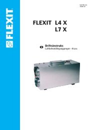
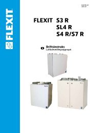
2.3 Sizes/Physical Dimensions<br />
<strong>S12</strong> X<br />
<strong>S12</strong> R<br />
<strong>S12</strong> X/<strong>S12</strong> R<br />
Water<br />
Right model<br />
Right model, front<br />
Right model<br />
Right model, front<br />
A<br />
B<br />
Front<br />
C<br />
D<br />
Left model, front<br />
Left model<br />
Left model, front<br />
5<br />
Dimensions (mm)<br />
(indicated on the figure<br />
to the left)<br />
A B C D<br />
<strong>S12</strong> R 60 80 230 264<br />
<strong>S12</strong> X 60 80 230 275<br />
All measures in mm
<strong>S20</strong> X <strong>S30</strong> X<br />
1630 1450<br />
795<br />
200<br />
1610<br />
Right model<br />
238 385 364 385 238<br />
Right model, front<br />
<strong>S20</strong> R <strong>S30</strong> R<br />
Right model<br />
Right model, front<br />
<strong>S20</strong> X/<strong>S30</strong> X/<strong>S20</strong> R/<strong>S30</strong> R<br />
Water<br />
B<br />
C<br />
250<br />
A<br />
1580<br />
500<br />
A<br />
C<br />
Front<br />
B<br />
Left model<br />
Left model, front<br />
6<br />
Left model<br />
Left model, front<br />
Dimensions (mm)<br />
(indicated on the<br />
figure to the left)<br />
A B C<br />
<strong>S20</strong> 85 515 225<br />
<strong>S30</strong> 85 565 225<br />
All measures in mm
3 Installation<br />
The unit is designed for indoor installation.<br />
3.1 Inspection/Maintenance<br />
The unit must be installed with space for service and<br />
maintenance (Fig. 1) such as filter replacement and<br />
cleaning the fans and exchanger. It is also important<br />
for the unit to be located so that the electrical cabinet<br />
is easily accessible for electrical connection, troubleshooting<br />
and future component replacement.<br />
3.2 Space Required<br />
Type A<br />
<strong>S12</strong> 900 mm<br />
<strong>S20</strong> 1000 mm<br />
<strong>S30</strong> 1100 mm<br />
See the separate dimensioned drawing for connection<br />
of the water battery (pipe location), Chap. 2.3. These<br />
are minimum requirements that only take service<br />
needs into account. If other statutory requirements<br />
require a greater distance, they must be complied with,<br />
for example for electrical safety.<br />
A<br />
3.3 Technical Room Requirements<br />
The unit must be placed in a separate technical room<br />
with a gully. Ceiling/floor/walls/doors must be in the<br />
necessary fire class.<br />
3.4 Recommended Sound Absorption and<br />
Sound Transfer<br />
The main silencers must be placed near the unit, preferably<br />
in the technical room. The unit should be placed<br />
by a wall that has no room on the other side that is<br />
sensitive to noise. The unit should not be less than 400<br />
mm from the wall. If the unit is placed against a wall,<br />
low-frequency sound may create vibrations in the wall.<br />
7<br />
Sound may also be transferred through the floor if the<br />
mass and rigidity of the floor are not sufficient.<br />
Technical rooms should be fitted with floating concrete<br />
floors to prevent sound transfer on account of vibration.<br />
When installing the unit, fabric bosses must be<br />
fitted between the unit and the duct system. It is also<br />
important for the unit not to bear the weight of the<br />
ducts. Busbars or water pipes must not prevent the<br />
unit from moving freely on the vibration dampers.<br />
3.5 Air Intake/Exhaust<br />
The distance between the air intake and air exhaust<br />
must be so great that air circulation is prevented.<br />
The fresh air intake must be placed away from traffic/smoke/dust/walls<br />
exposed to the sun. The air intake<br />
should be placed min. 1 m above ground level to reduce<br />
the risk of clogging with snow and leaves. When<br />
designing the intake/exhaust chambers, it is necessary<br />
to take drainage into account.<br />
Follow the suppliers’ recommendations for max./min.<br />
air flow rates through the intake/exhaust gratings/roof<br />
hats.<br />
Fig. 1<br />
3.6 Stop Damper in Air Intake/Exhaust<br />
(Accessory)<br />
Used to prevent self-ventilation when the unit is<br />
stopped.<br />
Must always be used in systems with water batteries as<br />
protection against frost.
4 Electrical Works<br />
All electrical works must be performed by an authorised electrician.<br />
• See the separate instructions for the automatic control and its installation.<br />
• See the separate wiring diagram in the unit for external connections.<br />
• See also Chapter 9 Technical Data for more information on electrical wiring.<br />
• A service switch must be installed for all-pole breaking of the supply voltage to the unit. This is not included<br />
in the supply from <strong>FLEXIT</strong>.<br />
• The electrical components must not be exposed to temperatures lower than -23 o C or higher than +55 o C.<br />
4.1 Main Supply (Mains Cable)<br />
The units require just one supply cable.<br />
See the separate table in Chapter 9 Technical Data for the exact dimensions of each unit.<br />
4.2 Connection of External Components<br />
See the separate wiring diagram enclosed with each unit. All electrical connections must be installed by qualified<br />
electricians.<br />
4.3 Earth-leakage Circuit-breaker<br />
The frequency converter must be earthed to comply with the regulations concerning high leakage<br />
currents (over 3.5 mA). If a line-side earth-leakage circuit-breaker is used as protection in<br />
accordance with the installation regulations, an earth-leakage circuit-breaker type B must be<br />
installed, which functions even if there are DC components. See the symbol in Fig. 2.<br />
!<br />
Tighten all terminal blocks before finishing the work to avoid heat generation in the contacts, which<br />
may result in fire in the worst case scenario.<br />
8<br />
Fig. 2 Earth-leakage<br />
symbol
5 Plumbing Works<br />
All plumbing work must be performed by an<br />
authorised plumber.<br />
5.1 Technical Data for Water Batteries<br />
Unit Water battery-<br />
connection<br />
Pipe<br />
connection<br />
<strong>S12</strong> X/R R 1/2" cu Ø12<br />
<strong>S20</strong> X/R R 3/4" cu Ø18<br />
<strong>S30</strong> X/R R 3/4" cu Ø18<br />
For further information, please refer to the special<br />
estimation program for calculation of technical data<br />
for the water battery (www.flexit.com).<br />
3-way valve<br />
Pump<br />
Hot water from<br />
boiler system<br />
Throttle valve<br />
Fig. 3 Recommended connection<br />
Water battery in the<br />
supply air system<br />
9<br />
5.2 Possible Valve Types<br />
3-way valve, type Honeywell, for capacity:<br />
1.6 kvs art. no. 56232<br />
2.5 kvs art. no. 57228<br />
4.0 kvs art. no. 56283<br />
2-way valve, type Honeywell, for capacity:<br />
1.6 kvs art. no. 56432<br />
2.5 kvs art. no. 56433<br />
4.0 kvs art. no. 56434<br />
5.3 Possible Valve Motor<br />
It is necessary to use a valve motor that is controlled<br />
by 0-10 V, where 10 V=100 % open.<br />
Valve motor article number: 56234.<br />
5.4 Connections<br />
Before connecting the water battery, it<br />
is necessary to check that the inspection<br />
doors are accessible and there is space<br />
enough to change the water battery.<br />
Use the recommended connection (see Fig. 3) unless<br />
specified otherwise. The water supply must be at the<br />
bottom of the water battery - the return must be on<br />
the top.<br />
Place the adjustment valve as close to the unit as<br />
possible. (Please note that many valve motors can go<br />
in both directions and this can be set on the motor.<br />
Set it so that the valve opens on an increasing 0-10 V<br />
signal.)<br />
If you use a water battery that has not had glycol<br />
(or another antifreeze) added, the unit should be in<br />
a heated room on account of the risk of frost in the<br />
battery. Install air dampers with spring-loaded return<br />
for outdoor air. Place the unit close to a gully to avoid<br />
damage caused by any water leaks.<br />
Install pipe routes to the water battery so that there is<br />
free access to the motor and recovery system.<br />
Remember vibration damping for water pipes.<br />
You can see the location of pipes out of the unit in the<br />
dimensioned drawings in Chap. 2.3.<br />
Install the water battery so that there is<br />
free access to the motor and exchanger<br />
cassette.<br />
Pipe routes for water pipes:<br />
Remember vibration damping for water<br />
pipes.
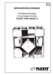
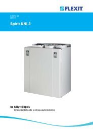
6 General Drawings and System<br />
Drawings<br />
6.1 Cross Heat Exchanger<br />
General Drawing - Cross Heat Exchanger<br />
1 (M1) Supply air fan<br />
2 (M2) Extract air fan<br />
3 (FI1) Supply air filter<br />
4 (FI2) Extract air filter<br />
5 (HR-X) Cross heat exchanger<br />
6 (M3) Bypass motor<br />
7 (B6) Thermoguard<br />
8 (EB1/WB1) Heating battery (electricity or water)<br />
9 (F10-19) Reset overheating thermostat*<br />
10 (P1) Supply air filter guard<br />
11 (P2) Extract air filter guard<br />
12 (P3) Supply air fan pressure guard*<br />
13 Connection box with automatic control<br />
System Drawing - Cross Heat Exchanger/Electric and<br />
Water Batteries<br />
M1 Supply air fan<br />
M2 Extract air fan<br />
M3 Bypass motor<br />
FI1 Supply air filter<br />
FI2 Extract air filter<br />
HR-X Cross heat exchanger<br />
P1 Supply air filter guard<br />
P2 Extract air filter guard<br />
P3 Supply air fan pressure guard *<br />
B1 Supply air temperature sensor<br />
B3 Extract air temperature sensor (not standard)<br />
B4 Outdoor air temperature sensor<br />
B5 Water battery temperature sensor (frost guard)<br />
B6 Thermoguard temperature sensor<br />
F10, F11 Overheating thermostat, manual reset *<br />
F20 Overheating thermostat *<br />
DA1 Air damper, exhaust air (not standard)<br />
DA2 Air damper, outdoor air (not standard)<br />
DA3 Air damper, heat exchanger<br />
WB1 Heating battery, water<br />
EB1 Heating battery, electric<br />
* Only with an electric battery<br />
10<br />
B1<br />
B1<br />
M1<br />
P2<br />
F10 F11<br />
EB1<br />
F20<br />
B3<br />
DA3<br />
M3<br />
FI2 FI1<br />
HR-X<br />
Unit with electric heating battery<br />
M1<br />
12<br />
P3<br />
13<br />
11<br />
1<br />
9<br />
B5<br />
WB1<br />
P2<br />
8<br />
4<br />
B3<br />
DA3<br />
M3<br />
DA2<br />
Unit with water-based heating battery<br />
7<br />
5<br />
6<br />
B6<br />
FI2 FI1<br />
HR-X<br />
DA2<br />
3<br />
B6<br />
B4<br />
B4<br />
10<br />
P1<br />
P1<br />
2<br />
DA1<br />
DA1<br />
M2<br />
M2
6.2 Rotor Heat Exchanger<br />
General Drawing - Rotor Heat Exchanger<br />
1 (M1) Supply air fan<br />
2 (M2) Extract air fan<br />
3 (FI1) Supply air filter<br />
4 (FI2) Extract air filter<br />
5 (HR-R) Rotor heat exchanger<br />
6 (M3) Bypass motor<br />
7 (B6) Thermoguard<br />
8 (EB1/WB1) Heating battery (electricity or water)<br />
9 (F10-19) Reset overheating thermostat*<br />
10 (P1) Extract air filter guard<br />
11 (P2) Supply air filter guard<br />
12 (P3) Supply air fan pressure guard*<br />
13 Connection box with automatic control<br />
System Drawing - Rotor Heat Exchanger/Electric and<br />
Water Batteries<br />
M1 Supply air fan<br />
M2 Extract air fan<br />
M3 Bypass motor<br />
FI1 Supply air filter<br />
FI2 Extract air filter<br />
HR-R Rotor heat exchanger<br />
P1 Supply air filter guard<br />
P2 Extract air filter guard<br />
P3 Supply air fan pressure guard *<br />
B1 Supply air temperature sensor<br />
B3 Extract air temperature sensor (not standard)<br />
B4 Outdoor air temperature sensor<br />
B5 Water battery temperature sensor (frost guard)<br />
B6 Thermoguard temperature sensor<br />
F10, F11 Overheating thermostat, manual reset *<br />
F20 Overheating thermostat *<br />
DA1 Air damper, exhaust air (not standard)<br />
DA2 Air damper, outdoor air (not standard)<br />
DA3 Air damper, heat exchanger<br />
WB1 Heating battery, water<br />
EB1 Heating battery, electric<br />
* Only with an electric battery<br />
11<br />
12<br />
B1<br />
M1<br />
9<br />
B1<br />
M1<br />
13<br />
P3<br />
1<br />
P2<br />
F10<br />
EB1<br />
F11<br />
B3<br />
FI2<br />
HR-R<br />
M4<br />
DA1 DA2<br />
M2<br />
F20 Unit with electric heating battery<br />
P2<br />
B1<br />
8<br />
WB1<br />
4<br />
5<br />
B3<br />
FI2<br />
10<br />
HR-R<br />
M4<br />
DA1<br />
M2<br />
Unit with water-based heating battery<br />
2<br />
3<br />
11<br />
FI1<br />
DA2<br />
FI1<br />
P1<br />
P1
7 Adjustment, Capacity and Sound Data<br />
The units have separate pressure measurement outlets. They are labelled on the unit. The <strong>S20</strong> and <strong>S30</strong><br />
have outlets on the top of the unit.<br />
The following formula is used:<br />
Q = k . P<br />
Q = Air flow rate (m 3 /h)<br />
k = Factor<br />
P = Pressure read off (Pa)<br />
K-factor:<br />
<strong>S12</strong> 60<br />
<strong>S20</strong> 80<br />
<strong>S30</strong> 96<br />
Example:<br />
Unit <strong>S30</strong><br />
Required: 2500 m 3 /h<br />
<strong>S30</strong> has k-factor=96<br />
Use formula: Q = k . P<br />
2500 = 96 P<br />
2500 = 96 . P<br />
96 96<br />
26 = P<br />
(26) 2 = P<br />
678 = P<br />
• Connect the pressure meter<br />
• Adjust the fan until 678 Pa is<br />
displayed on the instrument<br />
You have now adjusted the <strong>S30</strong> unit to<br />
a capacity of 2500 m 3 /h.<br />
12<br />
Fig. 4 Schematic diagram
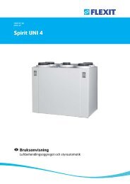
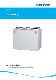
7.1 Capacity Diagram, Sound Data, Specifications - Flexit <strong>S12</strong> X EC W/E<br />
Supply air side (with F7 filter)<br />
Contact resistance (Pa)<br />
Extract air side (with F7 filter)<br />
Contact resistance (Pa)<br />
800<br />
600<br />
400<br />
200<br />
Pa<br />
l/s 0 100 200 300 400<br />
0<br />
Max<br />
80%<br />
60%<br />
40%<br />
Max<br />
80%<br />
60%<br />
87dB(A)<br />
40%<br />
85dB(A)<br />
75dB(A)<br />
80dB(A)<br />
70dB(A)<br />
m 0 400<br />
800 1200<br />
3 /h 1600<br />
Air flow rate in m 3 0 -5 -10 -20 -30 -45 Water Battery<br />
Pa<br />
0 35 45 55 65 75 F5-filter<br />
/h – Pressure correction factor<br />
800<br />
600<br />
400<br />
200<br />
Pa<br />
l/s 0 100 200 300 400<br />
1000<br />
0<br />
Pa<br />
0<br />
Max<br />
80%<br />
60%<br />
40%<br />
60%<br />
40%<br />
65dB(A)<br />
55dB(A)<br />
60dB(A)<br />
Air flow rate in m 3 35 45 55 65 75<br />
/h – Pressure correction factor<br />
Sound data is given at sound power level LwA in the<br />
capacity diagrams and is corrected with the table below<br />
for the various octave bands. Radiated noise produces<br />
Lw in the various octave bands and total LwA. This is<br />
read directly from the supply air table.<br />
Correction factor for LwA<br />
Hz 63 125 250 500 1000 2000 4000 8000 LwA<br />
Supply air -3 -2 -1 0 -8 -10 -16 -30<br />
Extract air 11 6 -1 0 -8 -15 -27 -40<br />
Radiated -40 -41 -37 -45 -43 -42 -45 -54 -36,6<br />
13<br />
80%<br />
70dB(A)<br />
m 0 400<br />
800 1200<br />
3 /h 1600<br />
Max<br />
600<br />
500<br />
400<br />
300<br />
200<br />
100<br />
F5-filter<br />
0<br />
600<br />
500<br />
400<br />
300<br />
200<br />
100<br />
0<br />
W<br />
W<br />
Power consumption in Watt<br />
Power consumption in Watt<br />
Data for supply air is measured in accordance with ISO 5136,<br />
the “In duct method”.<br />
Radiated noise is measured in accordance with ISO 9614-2.<br />
Bruel & Kjær measuring equipment, type 2260.<br />
Blue curves: Air capacity at various capacity settings in Volt.<br />
Green curves: Supply air fan power consumption at various capacity<br />
settings.<br />
Red curves: Sound power level LwA, cf. correction table.<br />
Light blue correction axis: Pressure increase using an EU-5 filter.<br />
Light green correction axis: Pressure reduction using a water battery.
7.2 Capacity Diagram, Sound Data, Specifications - Flexit <strong>S12</strong> R EC W/E<br />
Supply air side (with F7 filter)<br />
Contact resistance (Pa)<br />
Extract air side (with F7 filter)<br />
Contact resistance (Pa)<br />
1000<br />
800<br />
600<br />
400<br />
200<br />
Pa<br />
l/s 0 100 200 300 400<br />
0<br />
Max<br />
80%<br />
60%<br />
40%<br />
Max<br />
80%<br />
60%<br />
89dB(A)<br />
85dB(A)<br />
40% 75dB(A)<br />
80dB(A)<br />
70dB(A)<br />
m 0 400<br />
800 1200<br />
3 /h 1600<br />
Air flow rate in m 3 0 -5 -10 -20 -30 -45 Water Battery<br />
Pa<br />
0 35 45 55 65 75 F5-filter<br />
/h – Pressure correction factor<br />
800<br />
600<br />
400<br />
200<br />
Pa<br />
l/s 0 100 200 300 400<br />
1000<br />
0<br />
Max<br />
80%<br />
60%<br />
40%<br />
40%<br />
55dB(A)<br />
60%<br />
60dB(A)<br />
65dB(A)<br />
Air flow rate in m 3 m<br />
Pa<br />
0 400<br />
800 1200<br />
0 35 45 55 65 75<br />
/h – Pressure correction factor<br />
F5-filter<br />
3 /h 1600<br />
Sound data is given at sound power level LwA in the<br />
capacity diagrams and is corrected with the table below<br />
for the various octave bands. Radiated noise produces<br />
Lw in the various octave bands and total LwA. This is<br />
read directly from the supply air table.<br />
Correction factor for LwA<br />
Hz 63 125 250 500 1000 2000 4000 8000 LwA<br />
Supply air -5 -3 -2 0 -7 -10 -17 -30<br />
Extract air 10 7 1 0 -13 -19 -30 -42<br />
Radiated -40 -41 -37 -45 -43 -42 -45 -54 -36,6<br />
Max<br />
80%<br />
74dB(A)<br />
70dB(A)<br />
14<br />
600<br />
500<br />
400<br />
300<br />
200<br />
100<br />
0<br />
600<br />
500<br />
400<br />
300<br />
200<br />
100<br />
W<br />
0<br />
W<br />
Power consumption in Watt<br />
Power consumption in Watt<br />
Data for supply air is measured in accordance with ISO 5136,<br />
the “In duct method”.<br />
Radiated noise is measured in accordance with ISO 9614-2.<br />
Bruel & Kjær measuring equipment, type 2260.<br />
Blue curves: Air capacity at various capacity settings in Volt.<br />
Green curves: Supply air fan power consumption at various capacity<br />
settings.<br />
Red curves: Sound power level LwA, cf. correction table.<br />
Light blue correction axis: Pressure increase using an EU-5 filter.<br />
Light green correction axis: Pressure reduction using a water battery.
7.3 Capacity Diagram, Sound Data, Specifications - Flexit <strong>S20</strong> X W/E<br />
Supply air side (with F7 filter)<br />
Contact resistance (Pa)<br />
Extract air side (with F7 filter)<br />
Contact resistance (Pa)<br />
Pa<br />
Pa<br />
l/s 0 150 300 450 600<br />
1000<br />
800<br />
600<br />
400<br />
200<br />
0<br />
Max<br />
80%<br />
60%<br />
40%<br />
40%<br />
75dB(A)<br />
Air flow rate, m 3 /h - Pressure correction factor<br />
Air flow rate, m 3 /h - Pressure correction factor<br />
Sound data is given at sound power level LwA in the<br />
capacity diagrams and is corrected with the table below<br />
for the various octave bands (Lw). Radiated noise<br />
produces Lw in the various octave bands and total LwA.<br />
This is read directly from the supply air table.<br />
Correction factor for Lw<br />
Hz 63 125 250 500 1000 2000 4000 8000 LwA<br />
Supply air -2 -7 4 -4 -6 -14 -23 -37<br />
Extract air 21 10 3 -3 -15 -27 -32 -41<br />
Radiated -35 -29 -27 -28 -27 -28 -31 -46 -22<br />
15<br />
1400<br />
1200<br />
1000<br />
m 0 800 1600 2400<br />
3 /h 400 1200 2000<br />
0 -10 -20 -30 -45 -60 Water Battery<br />
Pa<br />
0 10 20 30 45 60 F5-filter<br />
60%<br />
80dB(A)<br />
80%<br />
l/s 0 150 300 450 600<br />
1000<br />
800<br />
600<br />
400<br />
200<br />
0<br />
85dB(A)<br />
m 0 800 1600 2400<br />
3 /h 400 1200 2000<br />
Pa<br />
0<br />
Max<br />
80%<br />
60%<br />
40%<br />
40%<br />
60%<br />
80%<br />
50 dB(A) 55dB(A)<br />
10 20 30 45 60<br />
Max<br />
60 dB(A)<br />
Max<br />
800<br />
600<br />
400<br />
200<br />
0<br />
1400<br />
1200<br />
1000<br />
800<br />
600<br />
400<br />
200<br />
0<br />
F5-filter<br />
W<br />
W<br />
Power consumption in Watt<br />
Power consumption in Watt<br />
Data for supply air is measured in accordance with ISO 5136,<br />
the “In duct method”.<br />
Radiated noise is measured in accordance with ISO 9614-2.<br />
Bruel & Kjær measuring equipment, type 2260.<br />
Blue curves: Air capacity at various capacity settings in Volt.<br />
Green curves: Supply air fan power consumption at various capacity<br />
settings.<br />
Red curves: Sound power level LwA, cf. correction table.<br />
Light blue correction axis: Pressure increase using an F5 filter.<br />
Light green correction axis: Pressure reduction using a water battery.
7.4 Capacity Diagram, Sound Data, Specifications - Flexit <strong>S20</strong> R W/E<br />
Supply air side (with F7 filter)<br />
Contact resistance (Pa)<br />
Extract air side (with F7 filter)<br />
Contact resistance (Pa)<br />
Pa<br />
l/s 0 150 300 450 600<br />
1000<br />
800<br />
600<br />
400<br />
200<br />
0<br />
Air flow rate, m 3 /h - Pressure correction factor<br />
Air flow rate, m 3 /h - Pressure correction factor<br />
Sound data is given at sound power level LwA in the<br />
capacity diagrams and is corrected with the table below<br />
for the various octave bands (Lw). Radiated noise<br />
produces Lw in the various octave bands and total LwA.<br />
This is read directly from the supply air table.<br />
Correction factor for Lw<br />
Hz 63 125 250 500 1000 2000 4000 8000 LwA<br />
Supply air -2 -7 4 -4 -6 -14 -23 -37<br />
Extract air 15 11 4 -3 -23 -33 -39 -48<br />
Radiated -35 -29 -27 -28 -27 -28 -31 -46 -22<br />
16<br />
1400<br />
1200<br />
1000<br />
m 0 800 1600 2400<br />
3 /h 400 1200 2000<br />
0 -10 -20 -30 -45 -60 Water Battery<br />
Pa<br />
0 10 20 30 45 60 F5-filter<br />
1000<br />
Pa<br />
Max<br />
80%<br />
60%<br />
40%<br />
40%<br />
75dB(A)<br />
60%<br />
80dB(A)<br />
80%<br />
85dB(A)<br />
l/s 0 150 300 450 600<br />
800<br />
600<br />
400<br />
200<br />
0<br />
m 0 800 1600 2400<br />
3 /h 400 1200 2000<br />
Pa<br />
0<br />
Max<br />
80%<br />
60%<br />
40%<br />
40%<br />
Max<br />
80%<br />
60%<br />
67dB(A)<br />
60dB(A) 65dB(A)<br />
10 20 30 45 60<br />
Max<br />
800<br />
600<br />
400<br />
200<br />
0<br />
1400<br />
0<br />
F5-filter<br />
W<br />
1200<br />
1000<br />
800<br />
600<br />
400<br />
200<br />
W<br />
Power consumption in Watt<br />
Power consumption in Watt<br />
Data for supply air is measured in accordance with ISO 5136,<br />
the “In duct method”.<br />
Radiated noise is measured in accordance with ISO 9614-2.<br />
Bruel & Kjær measuring equipment, type 2260.<br />
Blue curves: Air capacity at various capacity settings in Volt.<br />
Green curves: Supply air fan power consumption at various capacity<br />
settings.<br />
Red curves: Sound power level LwA, cf. correction table.<br />
Light blue correction axis: Pressure increase using an F5 filter.<br />
Light green correction axis: Pressure reduction using a water battery.
7.5 Capacity Diagram, Sound Data, Specifications - Flexit <strong>S30</strong> X W/E<br />
Supply air side (with F7 filter)<br />
Contact resistance (Pa)<br />
Extract air side (with F7 filter)<br />
Contact resistance (Pa)<br />
Pa<br />
1000<br />
Pa<br />
l/s 0 250 500 750 1000<br />
1200<br />
800<br />
600<br />
400<br />
200<br />
l/s 0 250 500 750 1000<br />
1200<br />
1000<br />
800<br />
600<br />
400<br />
200<br />
0<br />
0<br />
m 0 2000 4000<br />
3 /h 1000 3000<br />
Pa<br />
0<br />
Max<br />
80%<br />
60%<br />
40%<br />
Max<br />
80%<br />
60%<br />
40%<br />
60%<br />
40%<br />
87dB(A)<br />
85dB(A)<br />
80dB(A)<br />
75dB(A)<br />
Air flow rate, m 3 m 0 2000 4000<br />
0<br />
Pa<br />
/h - Pressure correction factor<br />
3 /h 1000 3000<br />
-15 -25 -35 -60 -90 Water Battery<br />
0<br />
10 15 20 30 40 F5-filter<br />
80%<br />
80%<br />
Max<br />
60%<br />
40%<br />
63dB(A)<br />
60dB(A)<br />
50dB(A) 55dB(A)<br />
10 15 20 30 40<br />
Air flow rate, m 3 /h - Pressure correction factor<br />
Sound data is given at sound power level LwA in the<br />
capacity diagrams and is corrected with the table below<br />
for the various octave bands (Lw). Radiated noise<br />
produces Lw in the various octave bands and total LwA.<br />
This is read directly from the supply air table.<br />
Correction factor for Lw<br />
Hz 63 125 250 500 1000 2000 4000 8000 LwA<br />
Supply air 4 -1 1 -1 -5 -13 -24 -35<br />
Extract air 22 12 -1 -6 -19 -30 -35 -42<br />
Radiated -34 -26 -25 -34 -36 -33 -39 -48 -28<br />
17<br />
Max<br />
2000<br />
F5-filter<br />
2000<br />
1800<br />
1600<br />
1400<br />
1200<br />
1000<br />
800<br />
600<br />
400<br />
200<br />
1800<br />
1600<br />
1400<br />
1200<br />
1000<br />
800<br />
600<br />
400<br />
200<br />
0<br />
0<br />
Power consumption in Watt<br />
W<br />
W<br />
Power consumption in Watt<br />
Data for supply air is measured in accordance with the ISO 5136<br />
“In duct method”. Radiated noise is measured in accordance<br />
with ISO 9614-2.<br />
Bruel & Kjær measuring equipment, type 2260.<br />
Blue curves: Air capacity at various capacity settings in Volt.<br />
Green curves: Supply air fan power consumption at various capacity<br />
settings.<br />
Red curves: Sound power level LwA, cf. correction table.<br />
Light blue correction axis: Pressure increase using an F5 filter.<br />
Light green correction axis: Pressure reduction using a water battery.
7.6 Capacity Diagram, Sound Data, Specifications - Flexit <strong>S30</strong> R W/E<br />
Supply air side (with F7 filter)<br />
Contact resistance (Pa)<br />
Extract air side (with F7 filter)<br />
Contact resistance (Pa)<br />
1000<br />
Pa<br />
l/s 0 250 500 750 1000<br />
1200<br />
800<br />
600<br />
400<br />
200<br />
0<br />
Max<br />
80%<br />
60%<br />
40%<br />
80%<br />
Air flow rate, m 3 /h - Pressure correction factor<br />
Air flow rate, m 3 10 15 20 30 40 F5-filter<br />
/h - Pressure correction factor<br />
Sound data is given at sound power level LwA in the<br />
capacity diagrams and is corrected with the table below<br />
for the various octave bands (Lw). Radiated noise<br />
produces Lw in the various octave bands and total LwA.<br />
This is read directly from the supply air table.<br />
Correction factor for Lw<br />
Hz 63 125 250 500 1000 2000 4000 8000 LwA<br />
Supply air 1 -1 2 -1 -6 -14 -24 -37<br />
Extract air 15 11 5 -5 -24 -35 -38 -46<br />
Radiated -34 -26 -25 -34 -37 -33 -39 -48 -28<br />
18<br />
Max<br />
60%<br />
87dB(A)<br />
40%<br />
80dB(A)<br />
75dB(A)<br />
85dB(A)<br />
2000<br />
1800<br />
1600<br />
1400<br />
1200<br />
1000<br />
200<br />
0<br />
m 0 2000 4000<br />
3 /h 1000 3000<br />
0 -50 -15 -35 -60 -90 Water Battery<br />
Pa<br />
0 10 15 20 30 40 F5-filter<br />
1000<br />
Pa<br />
l/s 0 250 500 750 1000<br />
1200<br />
800<br />
600<br />
400<br />
200<br />
0<br />
Max<br />
80%<br />
60%<br />
40%<br />
80%<br />
Max<br />
60%<br />
40%<br />
70dB(A)<br />
65dB(A)<br />
60dB(A)<br />
55dB(A)<br />
m 0 2000 4000<br />
3 /h 1000 3000<br />
Pa<br />
0<br />
800<br />
600<br />
400<br />
2000<br />
1800<br />
1600<br />
1400<br />
1200<br />
1000<br />
800<br />
600<br />
400<br />
W<br />
200<br />
0<br />
Power consumption in Watt<br />
Power consumption in Watt<br />
W<br />
Data for supply air is measured in accordance with ISO 5136,<br />
the “In duct method”.<br />
Radiated noise is measured in accordance with ISO 9614-2.<br />
Bruel & Kjær measuring equipment, type 2260.<br />
Blue curves: Air capacity at various capacity settings in Volt.<br />
Green curves: Supply air fan power consumption at various capacity<br />
settings.<br />
Red curves: Sound power level LwA, cf. correction table.<br />
Light blue correction axis: Pressure increase using an F5 filter.<br />
Light green correction axis: Pressure reduction using a water battery.
8 Maintenance<br />
You should inspect the system regularly. This must be performed by qualified operating personnel. The inspection<br />
should be performed twice a year, preferably in the spring and autumn. If the unit has a cross heat exchanger, you<br />
should check for leaks in the drain or water on the floor. If a water battery is used to heat the air, check also for water<br />
leaks. Listen for strange sounds and check for abnormal vibrations. Check at regular intervals that the air intake is free<br />
of snow and leaves. The inspection and maintenance of fans, exchanger cassettes, air dampers, filters and heating<br />
batteries are essential to achieve optimal performance.<br />
Exchanger<br />
cassette: As the system has filters installed with a high density class, it is not normally necessary to clean<br />
the exchanger cassette. If, for various reasons, it should still be necessary, dust can be removed<br />
with a soft brush. Further cleaning is possible if you remove the exchanger cassette, spray it with<br />
fat-soluble detergent and then blow it clean from the opposite side. Distance approximately 60<br />
mm and max. pressure 80 bar.<br />
NB ! Do not use detergent that is harmful to aluminium.<br />
Rotor: As the system has filters installed with a high density class, it is not normally necessary to clean<br />
the rotor. If, for various reasons, it should still be necessary, dust can be removed with a soft<br />
brush. Further cleaning is possible if you remove the rotor, spray it with fat-soluble detergent and<br />
then blow it clean from the opposite side. Distance approximately 60 mm and max. pressure 80<br />
bar.<br />
NB ! Do not use detergent that is harmful to aluminium and the environment.<br />
Check the drive belt and tighten it if necessary. Ensure that all seals around the rotor are intact<br />
and tight.<br />
Air dampers: The air damper plates are suspended in plastic bearings and do not need lubrication. The<br />
individual air damper plates are connected via an arm system that does not need lubrication.<br />
Check every year that the air damper is tight. If the air damper is not properly tight, it can be<br />
corrected by adjusting the air damper motor or possibly adjusting the arm tension.<br />
Filters: How frequently filters need replacing depends on the dust concentration in the air that passes<br />
through the filters. It is very important to replace filters to ensure that the system works properly.<br />
Filters must be replaced when the filter replacement lamp on the control panel lights up. They<br />
must be replaced at least once a year.<br />
Heating battery: The heating battery, electric or water-based, will be exposed to dirt very rarely, as the system<br />
has filters fitted with a high density class. If cleaning should still be necessary, you can use<br />
compressed air, which is blown in the opposite direction to the air flow, or a vacuum cleaner with a<br />
soft nozzle. Cleaning must be done carefully to ensure that the battery’s fins are not damaged.<br />
Inspect the cables to the electric battery at least twice a year. Check for damaged cables and<br />
components. Tighten all terminal blocks for power supply to the electric battery (elements,<br />
contactors, SSR) and other terminal blocks.<br />
Corrosion damage: If there is corrosion damage to fins or pipes, this may indicate moisture or corrosive air. The cause<br />
must be found and remedied.<br />
8.1 Troubleshooting<br />
Fault Remedial action Component<br />
The unit does not start 1. Check the fuses and that there is power to the unit<br />
2. Check the control panels in case the unit has stopped on account of an<br />
alarm or the service switch is off<br />
3. Check that the unit is not in STOP mode<br />
The heating does not<br />
come on<br />
1. Check that the pressure guard is OK (only with an electric battery)<br />
2. Check that the valve has control current (over 2 V) and supply voltage<br />
3. Check the temperature sensors<br />
The fans do not start 1. Check the operating setting<br />
2. Check that the fans have operating voltage and control current (over 2 V)<br />
3. Check that the motor protection is not active<br />
19<br />
Fuses, overheating<br />
protection, motor<br />
protection or frost sensor<br />
Pressure guard<br />
Sensors<br />
Valve<br />
Motor protection
9 Technical Specifications<br />
9.1 Technical Specifications, <strong>S12</strong> X<br />
<strong>S12</strong> X<br />
<strong>S12</strong> XW <strong>S12</strong> XE<br />
Rated voltage 230 V 400 V<br />
Fuse 1x10 A 3x16 A<br />
Rated current, total 9 A 16 A<br />
Rated power, total 1100 W 7100 W<br />
Rated power, electric<br />
battery<br />
6000 W<br />
Rated power, fans<br />
Rated preheating power<br />
2x485 W 2x485 W<br />
Fan type B-wheel B-wheel<br />
Fan motor control EC control EC control<br />
Max. fan speed 2500 RPM 2500 RPM<br />
Filter type (SUP/EXTR) F 7 F 7<br />
Filter dimensions (WxHxD,<br />
mm)<br />
592x294x250 mm 592x294x250 mm<br />
Number of bags 12 12<br />
Weight 185 kg 185 kg<br />
Duct connection Dia. 250 mm Dia. 250 mm<br />
Height 1380 mm 1380 mm<br />
Width 1250 mm 1250 mm<br />
Depth 700 mm 700 mm<br />
9.2 Technical Specifications, <strong>S12</strong> R<br />
<strong>S12</strong> R<br />
<strong>S12</strong> RW <strong>S12</strong> RE<br />
Rated voltage 230 V 400 V<br />
Fuse 1x10 A 3x16 A<br />
Rated current, total 9 A 16 A<br />
Rated power, total 1100 W 7100 W<br />
Rated power, electric<br />
battery<br />
6000 W<br />
Rated power, fans<br />
Rated preheating power<br />
2x485 W 2x485 W<br />
Fan type B-wheel B-wheel<br />
Fan motor control EC control EC control<br />
Max. fan speed 2500 RPM 2500 RPM<br />
Filter type (SUP/EXTR)<br />
Filter dimensions (WxHxD,<br />
mm)<br />
F 7 F 7<br />
Number of bags 12 12<br />
Weight 200 kg 200 kg<br />
Duct connection Dia. 250 mm Dia. 250 mm<br />
Height 1380 mm 1380 mm<br />
Width 1250 mm 1250 mm<br />
Depth 700 mm 700 mm<br />
592x294x250 mm 592x294x250 mm<br />
20
9.3 Technical Specifications, <strong>S20</strong> X/<strong>S30</strong> X<br />
<strong>S20</strong> X <strong>S30</strong> X<br />
<strong>S20</strong> XW <strong>S20</strong> XE <strong>S30</strong> XW <strong>S30</strong> XE<br />
Rated voltage 400 V 400 V 400 V 400 V<br />
Fuse 3x16 A 3x32 A 3x16 A 3x32 A<br />
Rated current, total 7.5 A 25 A 8.8 A 30 A<br />
Rated power, total 2800 W 14800 W 3350 W 18350 W<br />
Rated power, electric<br />
battery<br />
12000 W 15000 W<br />
Rated power, fans<br />
Rated preheating power<br />
2x1100 W 2x1100 W 2x1400 W 2x1400 W<br />
Fan type B-wheel B-wheel B-wheel B-wheel<br />
Fan motor control<br />
Frequency<br />
converter<br />
Frequency<br />
converter<br />
Frequency<br />
converter<br />
Frequency<br />
converter<br />
Max. fan speed 3000 RPM 3000 RPM 3000 RPM 3000 RPM<br />
Filter type (SUP/EXTR) F7 F7 F7 F7<br />
Filter dimensions<br />
(WxHxD, mm)<br />
360x695x350 360x695x350 400x795x380 400x795x380<br />
Number of bags 7 7 8 8<br />
Weight 296 kg 296 kg 319 kg 319 kg<br />
Duct connection 250x500 mm 250x500 mm 250x600 mm 250x600 mm<br />
Height 1580 mm 1580 mm 1680 mm 1680 mm<br />
Width 1610 mm 1610 mm 1690 mm 1690 mm<br />
Depth 795 mm 795 mm 895 mm 895 mm<br />
9.4 Technical Specifications, <strong>S20</strong> R/<strong>S30</strong> R<br />
<strong>S20</strong> R <strong>S30</strong> R<br />
<strong>S20</strong> RW <strong>S20</strong> RE <strong>S30</strong> RW <strong>S30</strong> RE<br />
Rated voltage 400 V 400 V 400 V 400 V<br />
Fuse 3x16 A 3x32 A 3x16 A 3x32 A<br />
Rated current, total 7.9 A 25 A 8.8 A 30 A<br />
Rated power, total 2800 W 14800 W 3350 W 18350 W<br />
Rated power, electric<br />
battery<br />
12000 W 15000 W<br />
Rated power, fans<br />
Rated preheating power<br />
2x1100 W 2x1100 W 2x1400 W 2x1400 W<br />
Fan type B-wheel B-wheel B-wheel B-wheel<br />
Fan motor control<br />
Frequency<br />
converter<br />
Frequency<br />
converter<br />
Frequency<br />
converter<br />
21<br />
Frequency<br />
converter<br />
Max. fan speed 3000 RPM 3000 RPM 3000 RPM 3000 RPM<br />
Filter type (SUP/EXTR) F7 F7 F7 F7<br />
Filter dimensions<br />
(WxHxD, mm)<br />
360x695x350 360x695x350 400x795x380 400x795x380<br />
Number of bags 7 7 8 8<br />
Weight 296 kg 296 kg 319 kg 319 kg<br />
Duct connection 250x500 mm 250x500 mm 250x600 mm 250x600 mm<br />
Height 1580 mm 1580 mm 1680 mm 1680 mm<br />
Width 1610 mm 1610 mm 1690 mm 1690 mm<br />
Depth 795 mm 795 mm 895 mm 895 mm
10 Commissioning<br />
!<br />
The unit must not be started until all documentation has been studied and all electrical and<br />
plumbing work has been performed.<br />
1 Familiarise yourself well with the documentation for the automatic control system<br />
2 Programme the various operating times and speeds (possibly including stop)<br />
3 Check that the correct temperature regulation and temperature settings have been selected. Are the sensors<br />
located correctly?<br />
4 Check that the fans rotate freely<br />
5 Check that all air dampers work. The unit must not be operated with closed air dampers.<br />
6 Check that all doors are properly closed<br />
7 Start the unit as described in the documentation for the automatic control<br />
8 Check that air dampers open (and close when the unit stops)<br />
9 Check that the heat recovery system works correctly<br />
10 Check that the heat control works correctly<br />
11 If the unit has a water battery, you must test the frost function. Cool the frost sensor to below 5 °C.<br />
The unit should stop and the air dampers close.<br />
12 Tighten all terminal blocks after commissioning<br />
22
11 EU Declaration of Conformity<br />
This declaration confirms that the products meet the requirements of the following Council Directives:<br />
89/336/EEC Electromagnetic Compatibility<br />
73/23/EEC Low Voltage Directive<br />
98/37/EEC Machinery Directive<br />
Manufacturer: <strong>FLEXIT</strong> AS, Televeien 15, N-1870 Ørje<br />
Tel: +47 69 81 00 00 Fax +47 69 81 00 80<br />
Type of equipment: 86 42 000 Ventilation equipment for mounting in ducts<br />
Model:<br />
Albatros <strong>S12</strong> - Kryss EL Albatros <strong>S20</strong> - XE Albatros <strong>S30</strong> - XE<br />
Albatros <strong>S12</strong> - Rotor EL Albatros <strong>S20</strong> - RE Albatros <strong>S30</strong> RE<br />
Albatros <strong>S12</strong> - Kryss W Albatros <strong>S20</strong> - XW Albatros <strong>S30</strong> - XW<br />
Albatros <strong>S12</strong> - Rotor W Albatros <strong>S20</strong> - RW Albatros <strong>S30</strong> - RW<br />
Serial no.: ..........................................<br />
The following harmonized EN 50081-1:92 EMC - Emission<br />
European standards or EN 50082-1:97 EMC - Immunity<br />
technical specifications EN 60335-1:1994 Safety<br />
have been applied: A11:95, A1:96, A12:96<br />
EN292, EN563, EN294<br />
<strong>FLEXIT</strong> AS<br />
Ørje, 12/04/2005 Pål J. Martinsen<br />
General Manager<br />
The right to give notice of lack of conformity applies to this product in accordance with the existing terms of sale, provided that the product is used<br />
correctly and maintained. Filters are consumables.<br />
The symbol on the product or on its packaging indicates that this product may not be treated as household waste. Instead it shall be handed over<br />
to the applicable collection point for the recycling of electrical and electronic equipment.<br />
By ensuring this product is disposed of correctly, you will help prevent potential negative consequences for the environment and human healthe,<br />
which could otherwisw be caused by inappropriate waste handeling of this product. For more detailed information, please contact your local city<br />
office, your household waste disposal service or the shop where you purchased the product.<br />
Notice of lack of conformity as a result of incorrect or defective installation must be submitted to the installation company responsible. The right to give<br />
notice of lack of conformity may lapse if the system is used incorrectly or maintenance is grossly neglected.<br />
23
12 Product/Environmental Declaration<br />
The declaration applies to ventilation units Flexit <strong>S12</strong> X/R, <strong>S20</strong> X/R, <strong>S30</strong> X/R<br />
Materials:<br />
Materials with which the user or treated air come into contact:<br />
• The unit’s outer walls are made of galvanised steel DX51D+Z275 (NS-EN 10142)<br />
• The rotor exchanger made of aluminium<br />
• Miscellaneous electric cables with PVC insulation<br />
• Electric motors consisting of galvanised steel, aluminium and copper<br />
• Heating elements made of steel<br />
• Air filters of glass fibre, sheet steel and EVA melting glue<br />
Materials in the unit with which service personnel may come into contact:<br />
• Plastic-insulated electric cables<br />
• Miscellaneous other electrical components<br />
• Insulation of type EPS/Dacron<br />
Other materials that may occur in small quantities:<br />
• Silicone sealant<br />
• Polyethylene foamed plastic<br />
• EPDM rubber gaskets<br />
• Miscellaneous steel screws, nuts and pop rivets, plus small quantities of copper and brass.<br />
Safety:<br />
Materials: The materials are considered to be completely harmless to users.<br />
Use: The unit is an electrical appliance which must be made dead for service and inspection. The unit<br />
also contains rotating motors that must have time to stop before the inspection door is opened,<br />
plus a heating element with a high operating temperature.<br />
24
Flexit AS, Televeien 15, N-1870 Ørje www.flexit.com