
You also want an ePaper? Increase the reach of your titles
YUMPU automatically turns print PDFs into web optimized ePapers that Google loves.
Touchscreen Driver installation • Community images for <strong>ODROID</strong>-C1<br />
<strong>ODROID</strong><br />
<strong>Magazine</strong><br />
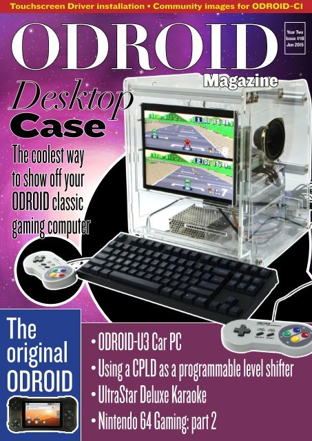
Desktop<br />
Case<br />
The coolest way<br />
to show off your<br />
<strong>ODROID</strong> classic<br />
gaming computer<br />
Year Two<br />
Issue #18<br />
Jun 2015<br />
The<br />
original<br />
<strong>ODROID</strong><br />
• <strong>ODROID</strong>-U3 Car PC<br />
• Using a CPLD as a programmable level shifter<br />
• UltraStar Deluxe Karaoke<br />
• Nintendo 64 Gaming: part 2
What we stand for.<br />
We strive to symbolize the edge of technology,<br />
future, youth, humanity, and engineering.<br />
Our philosophy is based on Developers.<br />
And our efforts to keep close relationships with<br />
developers around the world.<br />
For that, you can always count on having the quality<br />
and sophistication that is the hallmark of our products.<br />
Simple, modern and distinctive.<br />
So you can have the best to accomplish<br />
everything you can dream of.<br />
We are now shipping the <strong>ODROID</strong>-U3<br />
device to EU countries! Come and visit<br />
our online store to shop!<br />
Address: Max-Pollin-Straße 1<br />
85104 Pförring Germany<br />
Telephone & Fax<br />
phone: +49 (0) 8403 / 920-920<br />
email: service@pollin.de<br />
Our <strong>ODROID</strong> products can be found at<br />
http://bit.ly/1tXPXwe
EDITORIAL<br />
One of the Hardkernel engineers decided to build a case<br />
for his <strong>ODROID</strong> that looks like the Macintosh Plus model<br />
from his youth. We think he did a great job in creating<br />
a modern, futuristic version of that classic computer.<br />
Since we did a feature article on building a Truck PC last year,<br />
we’ve had requests for a similar<br />
article for sedan owners. In response,<br />
Belov replaced the standard<br />
built-in electronics gear in<br />
his Opel Astra using an <strong>ODROID</strong>-U3<br />
to provide both music and map services.<br />
Venkat also presents a cool project for<br />
your car that allows you to obtain detailed<br />
vehicle information via Bluetooth, download<br />
it to an <strong>ODROID</strong>, and plot the results using Google Earth.<br />
Tobias continues his Nintendo 64 series with reviews of several very<br />
popular N64 games, Nanik details the process of creating a custom service for Android,<br />
Bo teaches us how to install touchscreen drivers on an <strong>ODROID</strong>-C1, and Carsten presents<br />
his Guzunty Pi project of building an inexpensive UART console. We also find out<br />
how to turn an <strong>ODROID</strong> into a karaoke machine, play Tekken 6 in HD resolution, install<br />
some convenient community pre-built disk images, and much more!<br />
<strong>ODROID</strong> <strong>Magazine</strong>, published monthly at http://magazine.odroid.com, is your source for all things <strong>ODROID</strong>ian.<br />
Hard Kernel, Ltd. • 704 Anyang K-Center, Gwanyang, Dongan, Anyang, Gyeonggi, South Korea, 431-815<br />
Hardkernel manufactures the <strong>ODROID</strong> family of quad-core development boards and the world’s first ARM big.LITTLE single board computer.<br />
For information on submitting articles, contact odroidmagazine@gmail.com, or visit http://bit.ly/1ypImXs.<br />
You can join the growing <strong>ODROID</strong> community with members from over 135 countries at http://forum.odroid.com.<br />
Explore the new technologies offered by Hardkernel at http://www.hardkernel.com.
STAFF<br />
<strong>ODROID</strong><br />
<strong>Magazine</strong><br />
Rob Roy,<br />
Chief Editor<br />
I’m a computer<br />
programmer living<br />
and working in San<br />
Francisco, CA, designing<br />
and building web applications<br />
for local clients on my network<br />
cluster of <strong>ODROID</strong>s. My primary<br />
languages are jQuery, Angular JS<br />
and HTML5/CSS3. I also develop<br />
pre-built operating systems, custom<br />
kernels and optimized applications<br />
for the <strong>ODROID</strong> platform based<br />
on Hardkernel’s official releases, for<br />
which I have won several Monthly<br />
Forum Awards. I use my <strong>ODROID</strong>s<br />
for a variety of purposes, including<br />
media center, web server, application<br />
development, workstation, and<br />
gaming console. You can check out<br />
my 100GB collection of <strong>ODROID</strong><br />
software, prebuilt kernels and OS<br />
images at http://bit.ly/1fsaXQs.<br />
Nicole Scott,<br />
Art Editor<br />
I’m a Digital Strategist<br />
and Transmedia<br />
Producer<br />
specializing in online<br />
optimization and inbound marketing<br />
strategies, social media directing,<br />
and media production for print, web,<br />
video, and film. Managing multiple<br />
accounts with agencies and filmmakers,<br />
from Analytics and Adwords to<br />
video editing and DVD authoring. I<br />
own an <strong>ODROID</strong>-U3 which I use<br />
to run a sandbox web server, live in<br />
the California Bay Area, and enjoy<br />
hiking, camping and playing music.<br />
Visit my web page at http://www.nicolecscott.com.<br />
Bo<br />
Lechnowsky,<br />
Editor<br />
I am President of Respectech,<br />
Inc., a technology<br />
consultancy in Ukiah,<br />
CA, USA that I founded in 2001.<br />
From my background in electronics<br />
and computer programming, I manage<br />
a team of technologists, plus develop<br />
custom solutions for companies ranging<br />
from small businesses to worldwide<br />
corporations. <strong>ODROID</strong>s are one of<br />
the weapons in my arsenal for tackling<br />
these projects. My favorite development<br />
languages are Rebol and Red,<br />
both of which run fabulously on ARMbased<br />
systems like the <strong>ODROID</strong>-U3.<br />
Regarding hobbies, if you need some,<br />
I’d be happy to give you some of mine<br />
as I have too many. That would help<br />
me to have more time to spend with my<br />
wonderful wife of 23 years and my four<br />
beautiful children.<br />
James<br />
LeFevour,<br />
Art Editor<br />
I am a Digital Media<br />
Specialist who is<br />
also enjoying freelance<br />
work in social network marketing and<br />
website administration. The more I<br />
learn about <strong>ODROID</strong> capabilities, the<br />
more excited I am to try new things I’m<br />
learning about. Being a transplant to<br />
San Diego from the Midwest, I am still<br />
quite enamored with many aspects that<br />
I think most West Coast people take for<br />
granted. I live with my lovely wife and<br />
our adorable pet rabbit; the latter keeps<br />
my books and computer equipment in<br />
constant peril, the former consoles me<br />
when said peril manifests.<br />
Bruno Doiche,<br />
Senior<br />
Art Editor<br />
Nothing gets into<br />
our Senior Art Editor’s<br />
blood as the rush of long nights doing<br />
and re-doing the cover of the magazine.<br />
As a Gemini, he actually enjoys it, even<br />
when his family strives to get his attention<br />
and figure out what he wants<br />
for his birthday. How old is Bruno?<br />
100101 years old!<br />
Manuel<br />
Adamuz,<br />
Spanish<br />
Editor<br />
I am 31 years old<br />
and live in Seville,<br />
Spain, and was born in Granada. I<br />
am married to a wonderful woman<br />
and have a child. A few years ago I<br />
worked as a computer technician and<br />
programmer, but my current job is<br />
related to quality management and<br />
information technology: ISO 9001,<br />
ISO 27001, and ISO 20000. I am<br />
passionate about computer science,<br />
especially microcomputers such as the<br />
<strong>ODROID</strong> and Raspberry Pi. I love<br />
experimenting with these computers.<br />
My wife says I’m crazy because I just<br />
think of <strong>ODROID</strong>s! My other great<br />
hobby is mountain biking, and I occasionally<br />
participate in semi-professional<br />
competitions.
INDEX<br />
U3 Car pc - 6<br />
Obdgps - 9<br />
<strong>ODROID</strong> FORUMS - 16<br />
Nintendo 64 emulation - 17<br />
Touchscreen - 26<br />
n64 core - 28<br />
community Images - 28<br />
odroid history - 29<br />
SBC comparison - 30<br />
desktop case - 38<br />
gUzunty pi - 41<br />
android development - 46<br />
karAoke - 48<br />
TEKKEN 6 - 50<br />
MEET AN <strong>ODROID</strong>IAN - 51
CAR PC<br />
<strong>ODROID</strong>-U3<br />
Car PC<br />
REplacing the<br />
standard FACTORY<br />
equipment<br />
by Belov Vitaly<br />
My car, an Opel Astra H, came<br />
factory-equipped with a radio<br />
and CD MP3 player as well<br />
as a black-and-white 4-inch graphic display.<br />
I was not satisfied with the lack<br />
of USB input for connecting flash drives<br />
with MP3 music, and I had to use a<br />
smartphone for navigation, which constantly<br />
requires a battery charge and can<br />
only be placed on the windshield. At<br />
first, I bought a commercial pre-built device<br />
to replace the head unit, which was<br />
very uncomfortable, because the screen<br />
of the device was too low, at the level<br />
of my stomach. Another option was to<br />
mount a 7 inch tablet, such as the Nexus<br />
7, but it didn’t fit into the frame, since<br />
the standard Astra H only has space for a<br />
6.5-inch LCD, which was too small for<br />
me. I then decided to build an Android<br />
CarPC and install it in place of the black<br />
and white display.<br />
Completed Car PC installation<br />
Component diagram<br />
I needed the following functionality<br />
from my CarPC:<br />
• Navigation<br />
• Mp3 player<br />
• Internet radio<br />
• Video player<br />
• Rear view camera<br />
I chose an <strong>ODROID</strong>-U3 as the basis<br />
since it is an inexpensive but powerful<br />
computer with excellent performance<br />
and plenty of memory.<br />
Components<br />
• <strong>ODROID</strong>-U3 with 8Gb eMMC<br />
• RTC (Real Time Clock) battery<br />
• 7” 1280x800 IPS LCD with 5<br />
points capacitive multitouch<br />
• Frame for 7” LCD (my own development,<br />
3D printing)<br />
• Bluetooth USB dongle<br />
• Wi-Fi USB dongle<br />
• HUAWEI E1550 3G USB modem<br />
• GPS/GLONASS USB Holux<br />
M-215+<br />
<strong>ODROID</strong> MAGAZINE 6
CAR PC<br />
• EasyCap USB with an STK1160<br />
chip for the rear view camera<br />
• OBD2 Bluetooth adapter<br />
• Rear view camera<br />
• Power supply DC to DC 12V to<br />
5V with 4-port USB hub<br />
• ELM327 OBD2 adapter<br />
I was not able to find a ready-made<br />
frame for the 7-inch LCD, so I had to<br />
do it myself. The frame layout for 7”<br />
LCD was created in SolidWorks and<br />
then printed on a 3D printer. I then<br />
plastered, sanded and painted the frame<br />
in matte black, which fit perfectly, giving<br />
a visible area of 152.5x91.5mm. The<br />
display was attached to the frame using<br />
0.5mm double-sided tape.<br />
I chose a ChalkElec 7-inch LCD<br />
with a resolution of 1280x800 pixels<br />
and 5 points multi-touch The LCD is<br />
very bright with good contrast, and the<br />
image is clearly visible in sunlight. The<br />
<strong>ODROID</strong>-U3 has a micro HDMI input,<br />
and the screen from ChalkElec has<br />
a mini HDMI input. Since this cable<br />
is not readily available, I had to make it<br />
myself. The multi-touch cable is connected<br />
to the <strong>ODROID</strong>-U3 via USB<br />
port, with single-touch capacity working<br />
out of the box. To support 5-point<br />
multi-touch, you need to compile the<br />
kernel with support for ChalkBoard<br />
Touch, which is detailed in the “Giant<br />
Tablet” article in the February 2014 issue<br />
of <strong>ODROID</strong> <strong>Magazine</strong>.<br />
Smart Power Supply<br />
The <strong>ODROID</strong>-U3 requires 5 volts,<br />
and there are a large number of 12V to<br />
5V converters with a variety of power<br />
LCD frame components<br />
Assembled LCD Frame<br />
available commercially. However, I<br />
wanted to automate turning the CarPC<br />
on and off depending on the position of<br />
the ignition key, which is indicated by<br />
the ACC signal from the car, requiring a<br />
custom power supply. I chose the chip<br />
LT1374 for the 12V to 5V converter. It<br />
is quite simple, and consumes very little<br />
energy in standby mode, yet delivers<br />
current up to 2A and has on/off control<br />
input. The cheapest microcontroller<br />
(MC) ATTINY13 was used in order<br />
to automate the power supply with the<br />
ACC control signal.<br />
Algorithm<br />
• On first start, the microcontroller engages<br />
and monitors the ACC signal.<br />
• when the ACC signal is on, the periphery<br />
is powered, and after a couple<br />
of seconds, the <strong>ODROID</strong>-U3 is<br />
powered.<br />
Smart Power Supply front and rear view<br />
• when the ACC signal is off, the “Power”<br />
button pressing is emulated, the<br />
<strong>ODROID</strong>-U3 goes to “Sleep mode”,<br />
and “Airplane mode” is turned on.<br />
• when the ACC signal is off, after 1<br />
second, the “Power” button pressing<br />
is emulated, the <strong>ODROID</strong>-U3<br />
wakes up, and “Airplane mode” is<br />
turned off.<br />
• when the ACC signal is off for more<br />
than 30 seconds, the car battery is<br />
monitored so that at less than 11.5V,<br />
everything depowered except the microcontroller.<br />
• when the ACC signal is off for more<br />
than 14 hours, the <strong>ODROID</strong>-U3 is<br />
depowered.<br />
USB Hub<br />
An assembled USB hub is also<br />
mounted on the power supply. In order<br />
to work in the car at low temperatures<br />
during the Russian winter, I selected<br />
the industrial chip AT43301 (ATMEL),<br />
which works at temperatures as low as<br />
-40˚C. To filter out noise on all lines of<br />
power, ferrite beads (FB) were installed<br />
on the USB hub. Without ferrite beads,<br />
the chip on the integrated USB hub on<br />
the <strong>ODROID</strong>-U3 board will occasionally<br />
freeze.<br />
<strong>ODROID</strong> MAGAZINE 7
CAR PC<br />
Android and<br />
software<br />
The latest Android 4.4.4 KitKat 4.5<br />
image from Hardkernel supports many<br />
devices automatically, but does not support<br />
ChalkBoard Touch and EasyCap,<br />
which makes it necessary to compile a<br />
kernel for use with these devices. However,<br />
there is a simpler solution. Thanks<br />
to <strong>ODROID</strong> forum member @voodik,<br />
there is an Android 4.4.4 KitKat Cyanogenmod<br />
11.0 community image which<br />
already supports ChalkBoard Touch and<br />
EasyCap, which may be downloaded<br />
from http://bit.ly/1Lc2nWW.<br />
For correct operation of the GPS receiver,<br />
you must specify the correct baud<br />
rate of the receiver and number of USB<br />
port in the file /system/build.prop. For<br />
my <strong>ODROID</strong>-U3, the port is ttyUSB3,<br />
and the speed is 4800:<br />
installed the Automate It app. After disabling<br />
the ACC signal, a power button<br />
press is emulated by Automate It, along<br />
with toggling Airplane mode.<br />
Installation<br />
To mount the screen, I glued the<br />
LCD to the frame using a thin doublesided<br />
tape. I then secured the power<br />
supply and <strong>ODROID</strong>-U3 using a custom<br />
metal bracket, and connected all<br />
USB devices. For power, I used individual<br />
12V wires from the car battery<br />
to my CarPC. The audio output of the<br />
<strong>ODROID</strong>-U3 was then connected to<br />
the AUX input of the head unit of the<br />
car, and I mounted the GPS receiver in<br />
the side of the rack windshield.<br />
pastebin.ca/3002845 and copy it into<br />
the new project. Compile the code in<br />
order to produce a HEX firmware file,<br />
then flash the HEX file to the Attiny13<br />
using Arduino software.<br />
Everything now works great in my<br />
car. Using an <strong>ODROID</strong>-U3 board,<br />
I created a powerful and fast CarPC,<br />
which improved open the original capabilities<br />
of the factory-installed system.<br />
The combination of Android and your car<br />
makes a cost-effective alternative to the<br />
stock factory equipment<br />
ro.kernel.android.gps=ttyUSBx<br />
ro.kernel.android.gps.speed=xxxx<br />
Once the system is installed, you<br />
must install the GoogleApps Installer<br />
application in order to use the Google<br />
Play Store. For the home screen, I chose<br />
the app called BigLauncher, which is designed<br />
for elderly or visually impaired<br />
people, since it has large icons and is<br />
very well suited for use in the car. To<br />
listen to MP3 music, I installed Power-<br />
Amp, and PC Radio for Internet radio.<br />
For viewing photos, I chose Quick Pic,<br />
and for playing videos, I used MX Player.<br />
For connecting the mobile phone to<br />
the CarPC, I installed Tablet Talk, and<br />
configured Torque Pro for communication<br />
between the on-board car computer<br />
using an OBD2 adapter. To reduce energy<br />
consumption in sleep mode, I also<br />
Android Home Screen<br />
View of assembled CarPC before installation<br />
in the vehicle<br />
The CarPC connects to the Internet<br />
via a hotspot from my mobile phone.<br />
Also, just in case the phone runs out of<br />
battery, a 3G USB dongle was connected<br />
to the CarPC.<br />
Software<br />
The code for Attiny13 was written in<br />
CodeVisionAVR, which is available at<br />
http://bit.ly/1RY4G4s. To flash the Attiny13<br />
with the controller code, create a<br />
new blank project in CodeVisionAVR,<br />
then download the code from http://<br />
With an <strong>ODROID</strong>-U3 Car PC, you will be<br />
the envy of all of your friends<br />
<strong>ODROID</strong> MAGAZINE 8
OBDGPS<br />
OBDGPS<br />
Logger<br />
COMBINE OBDII<br />
AND GPS data FOR<br />
COMPLETE VEHICLE<br />
TRACKING<br />
by Venkat Bommakanti<br />
In the May 2015 issue, I introduced<br />
the powerful combination of an<br />
<strong>ODROID</strong>-C1 and a USB GPS<br />
module in order to track vehicles using<br />
OpenGTS. What if we could further<br />
enhance that combination by adding<br />
vehicle diagnostics to the mix? Well,<br />
On-Board Diagnostics (OBDII) does<br />
exactly that! This article outlines how to<br />
get both the USB GPS and a bluetooth<br />
OBDII adapter working synchronously<br />
with the C1 using the open-source package<br />
called OBDGPSLogger, which may<br />
be used with vehicles made after 1999.<br />
OBDGPSLogger is a C-based command-line<br />
solution designed to run on<br />
Linux with the acquired data saved to a<br />
local SQLite database. It does not come<br />
with any native database management<br />
front-end. However, to assist with the<br />
management of the OBD and GPS data,<br />
this example uses a browser-based management<br />
option utilizing Nginx as the<br />
web server, PHP as the scripting engine,<br />
and phpLiteAdmin as the SQLite database<br />
administration frontend.<br />
It is possible to migrate this to a<br />
MySQL-based solution or use other<br />
utilities like pyOBD, which is a Pythonbased<br />
open-source utility for acquiring<br />
OBD data, but only the basic setup will<br />
be detailed here. Refer to the May 2015<br />
OpenGTS article for instructions on setting<br />
up, configuring, and validating the<br />
USB GPS adapter.<br />
Requirements<br />
1. An <strong>ODROID</strong>-C1, although these<br />
steps can also apply to a more powerful<br />
<strong>ODROID</strong> system.<br />
2. Required C1 accessories such as an<br />
HDMI cable, a CAT 5E+ ethernet cable<br />
or WIFI 3 adapter, a Bluetooth adapter<br />
module 2 (BT 4.0+), a power supply<br />
unit, an RTC battery, and an HDMIcompatible<br />
monitor, <strong>ODROID</strong>-VU or<br />
3.2” touchscreen.<br />
3. A 16GB+ eMMC 5.0 module or<br />
microSD card with the latest Lubuntu<br />
desktop image, and an SD card reader/<br />
writer.<br />
4. A USB GPS module from Hardkernel,<br />
available at http://bit.ly/1EPERhm.<br />
5. A compatible OBDII (v1.5+) Bluetooth<br />
adapter with an ELM327 interface,<br />
such as the one produced by Panlong.<br />
6. A network where the device has access<br />
to the internet and the <strong>ODROID</strong><br />
forums.<br />
7. OBDGPSLogger software (Version:<br />
0.16) gpsd and gpsd-client.<br />
8. Networked access to the C1 via utilities<br />
like PuTTY, FileZilla, TightVNC<br />
Viewer (MS Windows 7+), or Terminal<br />
(Mac, Linux), from a testing desktop.<br />
9. LiPo battery packs with at least<br />
two (2) USB ports providing 2A+ each:<br />
one for the VU (if 3.2” Touchscreen<br />
not used) and another for the C1 itself,<br />
along with C1-compatible USB-DC<br />
Figure 1: Assembled C1, GPS, OBDII,<br />
Touchscreen and Battery portable setup<br />
plug cables, available from Hardkernel.<br />
Install Lubuntu<br />
Install the latest C1 image onto the<br />
eMMC module or SD card and attach<br />
it to the <strong>ODROID</strong>. With the display<br />
attached, boot up the system. Run the<br />
<strong>ODROID</strong> Utility and set the display<br />
resolution, then reboot.<br />
Expand the installation partition<br />
to use all of the available drive space<br />
by selecting the “Resize your root partition”<br />
option. Reboot and re-run the<br />
<strong>ODROID</strong> Utility to configure and update<br />
all remaining relevant aspects of the<br />
system, and reboot again.<br />
Ensure you are logged in as the default<br />
odroid user, unless otherwise specified.<br />
Type the following commands in<br />
a Terminal window in order to update<br />
the operating system files, system kernel,<br />
and related applications:<br />
<strong>ODROID</strong> MAGAZINE 9
OBDGPS<br />
$ sudo apt-get autoremove && sudo<br />
apt-get update<br />
$ sudo apt-get dist-upgrade &&<br />
sudo apt-get upgrade<br />
$ sudo apt-get install linuximage-c1<br />
Shutdown the <strong>ODROID</strong>, attach all<br />
of the accessories and cables, including<br />
the GPS and Bluetooth adapters, then<br />
reboot. Check the system version from<br />
a Terminal window using the following<br />
command to ensure you have the latest<br />
version:<br />
$ uname -a<br />
Linux odroid 3.10.75-84 #1 SMP<br />
PREEMPT Sat Apr 25 18:33:08 BRT<br />
2015 armv7l armv7l armv7l GNU/<br />
Linux<br />
Setup Bluetooth<br />
Install additional utilities using the<br />
following commands:<br />
$ sudo apt-get install bluez-dbg<br />
bluez-hcidump bluez-utils blueztools<br />
$ sudo apt-get install bluewho<br />
blueman python-bluetooth<br />
Then, check the USB information related<br />
to the adapters:<br />
$ lsusb<br />
…<br />
Bus 001 Device 005: ID 0b05:17cb<br />
ASUSTek Computer, Inc.<br />
Bus 001 Device 004: ID 1546:01a6<br />
U-Blox AG<br />
…<br />
Note that I used an <strong>ODROID</strong>-compatible<br />
ASUS Bluetooth 4.0 adapter in<br />
place of the Hardkernel model. Check<br />
the Bluetooth adapter’s support for additional<br />
features such as RFCOMM protocol<br />
by examining the dmesg logs:<br />
$ dmesg | grep Blue<br />
[ 0.851848@0] Bluetooth: Core<br />
ver 2.16<br />
[ 0.859721@0] Bluetooth: HCI<br />
device and connection manager<br />
initialized<br />
[ 0.866240@0] Bluetooth: HCI<br />
socket layer initialized<br />
[ 0.871245@0] Bluetooth:<br />
L2CAP socket layer initialized<br />
[ 0.876447@0] Bluetooth: SCO<br />
socket layer initialized<br />
[ 1.429422@2] Bluetooth: HCI<br />
UART driver ver 2.2<br />
[ 1.433876@2] Bluetooth: HCI<br />
H4 protocol initialized<br />
[ 1.438828@2] Bluetooth: HCI<br />
BCSP protocol initialized<br />
[ 1.443919@2] Bluetooth:<br />
HCILL protocol initialized<br />
[ 1.448782@2] Bluetooth: HCI-<br />
ATH3K protocol initialized<br />
[ 1.453877@2] Bluetooth: HCI<br />
Three-wire UART (H5) protocol<br />
initialized<br />
[ 3.236424@2] Bluetooth: btwake_control_init<br />
Driver Ver 1.1<br />
[ 3.366366@2] Bluetooth: RF-<br />
COMM TTY layer initialized<br />
[ 3.371156@2] Bluetooth: RF-<br />
COMM socket layer initialized<br />
[ 3.376392@2] Bluetooth: RF-<br />
COMM ver 1.11<br />
[ 3.380308@2] Bluetooth: BNEP<br />
(Ethernet Emulation) ver 1.3<br />
[ 3.385744@2] Bluetooth: BNEP<br />
filters: protocol multicast<br />
[ 3.397895@2] Bluetooth: BNEP<br />
socket layer initialized<br />
[ 3.402975@2] Bluetooth: HIDP<br />
(Human Interface Emulation) ver<br />
1.2<br />
[ 3.409060@2] Bluetooth: HIDP<br />
socket layer initialized<br />
Check the installed Bluetooth modules:<br />
$ dpkg -l | grep blue<br />
ii blueman ...<br />
armhf Graphical bluetooth manager<br />
ii bluez ...<br />
armhf Bluetooth tools and daemons<br />
ii bluez-alsa:armhf ...<br />
armhf Bluetooth ALSA support<br />
ii bluez-cups ...<br />
armhf Bluetooth printer driver<br />
for CUPS<br />
ii libbluetooth-dev ...<br />
armhf Dev. files for BlueZ Linux<br />
Bluetooth lib<br />
ii libbluetooth3:armhf ...<br />
armhf Library to use the BlueZ<br />
Linux BT stack<br />
ii libgnome-bluetooth11 ...<br />
armhf GNOME Bluetooth tools -<br />
support library<br />
Check for the presence of the Bluetooth<br />
device, which will be useful for<br />
connection configuration:<br />
$ hcitool dev<br />
Devices:<br />
hci0 00:02:72:CC:F4:CE<br />
$ hciconfig<br />
hci0: Type: BR/EDR Bus: USB<br />
BD Address: 00:02:72:CC:F4:CE<br />
ACL MTU: 1021:8 SCO MTU: 64:1<br />
UP RUNNING PSCAN<br />
RX bytes:583 acl:0 sco:0<br />
events:33 errors:0<br />
TX bytes:898 acl:0 sco:0 commands:33<br />
errors:0<br />
$ sudo rfkill list all<br />
0: hci0: Bluetooth<br />
Soft blocked: no<br />
Hard blocked: no<br />
Configure Bluetooth<br />
From the lubuntu desktop, launch<br />
the Bluetooth Manager configuration<br />
utility as shown in Figure 2. Then, select<br />
the Preferences menu item to configure<br />
the application, according to Figure 3.<br />
Using Figure 4 as a reference, update the<br />
friendly name of the Bluetooth adapter<br />
to a meaningful one like “c1-1-0”. Make<br />
the device always visible for other Bluetooth<br />
devices to scan and find it. Save<br />
<strong>ODROID</strong> MAGAZINE 10
OBDGPS<br />
the configuration and reboot.<br />
Figure 2 - Launch Bluetooth Manager<br />
Figure 3 - Bluetooth Manager configuration<br />
Figure 4 - Bluetooth Manager configuration<br />
update<br />
Testing Bluetooth<br />
If necessary, you can use the command-line<br />
Bluetooth packet analyzer/<br />
sniffer to analyze Bluetooth traffic for<br />
debugging purposes:<br />
$ sudo hcidump<br />
HCI sniffer - Bluetooth packet<br />
analyzer ver 2.5<br />
device: hci0 snap_len: 1500 filter:<br />
0xffffffff<br />
< HCI Command: Write Class of Device<br />
(0x03|0x0024) plen 3<br />
class 0x700100<br />
> HCI Event: Command Complete<br />
(0x0e) plen 4<br />
Write Class of Device<br />
(0x03|0x0024) ncmd 1<br />
status 0x00<br />
< HCI Command: Write Extended<br />
Inquiry Response (0x03|0x0052)<br />
plen 241<br />
fec 0x00<br />
Complete local name: ‘c1-1-<br />
0’<br />
TX power level: 0<br />
Complete service classes:<br />
0x112d 0x1112 0x111f 0x111e<br />
0x110c 0x110e 0x1105<br />
> HCI Event: Command Complete<br />
(0x0e) plen 4<br />
Write Extended Inquiry Response<br />
(0x03|0x0052) ncmd 1<br />
status 0x00<br />
< HCI Command: Write Extended<br />
Inquiry Response (0x03|0x0052)<br />
plen 241<br />
fec 0x00<br />
Complete local name: ‘c1-1-<br />
0’<br />
TX power level: 0<br />
Complete service classes:<br />
0x112d 0x1112 0x111f 0x111e<br />
0x110c 0x110e ...<br />
> HCI Event: Command Complete<br />
(0x0e) plen 4<br />
Write Extended Inquiry Response<br />
(0x03|0x0052) ncmd 1<br />
status 0x00<br />
...<br />
Another useful tool is Wireshark to<br />
give a graphic view of the snooped data,<br />
which may be installed by typing the<br />
following command into any Terminal<br />
window:<br />
$ sudo apt-get install wireshark<br />
After installation, you can launch<br />
Wireshark version 1.10.6 following the<br />
steps illustrated in Figure 5. The welcome<br />
screen should appear as seen in<br />
Figure 6, indicating that the Bluetooth<br />
adapter on the C1 has been detected.<br />
Figure 5 - Launch Wireshark<br />
Figure 6 - Wireshark welcome screen<br />
with Bluetooth adapter detected<br />
Figure 7 - Wireshark with snooped<br />
Bluetooth traffic<br />
Click on the green shark fin icon to<br />
request start of a capture, then launch<br />
the Bluetooth Manager application and<br />
click on the Search button after the application<br />
has loaded. You should immediately<br />
see all of the snooped Bluetooth<br />
traffic and related information appear in<br />
the Wireshark application window, as illustrated<br />
in Figure 7.<br />
<strong>ODROID</strong> MAGAZINE 11
OBDGPS<br />
Install gpsd<br />
Install gpsd and relevant utilities using<br />
the following command. For detailed<br />
information on configuration,<br />
testing and usage, please refer to the May<br />
2015 OpenGTS article.<br />
$ sudo apt-get install gpsd gpsdclients<br />
&& sudo reboot<br />
Install web server<br />
tools<br />
OBDGPSLogger stores the collected<br />
OBDII and GPS data in a local<br />
SQLite3 database. It does not include<br />
a native database management tool. To<br />
help with possible database management<br />
needs, I have also included the installation<br />
of nginx web server and PHP along<br />
with phpLiteAdmin in order to display<br />
the SQLite3 administrative GUI. First,<br />
install the following:<br />
$ sudo apt-get install nginx-full<br />
sqlite3<br />
$ sudo apt-get install autoconf<br />
automake autotools-dev libtool<br />
curl<br />
$ sudo apt-get install libcurl4-<br />
openssl-dev lbzip2<br />
$ sudo apt-get install php5 php5-<br />
dev php5-cgi php5-fpm php5-curl<br />
php5-gd<br />
$ sudo apt-get install php5-<br />
sqlite php5-gmp php5-imagick<br />
php5-imap php5-intl<br />
$ sudo apt-get install php5-ldap<br />
php5-mcrypt libmcrypt-dev phpxml-parser<br />
$ sudo apt-get install php5-xsl<br />
php-apc<br />
Then, update nginx configuration to<br />
enable PHP5 support:<br />
$ sudo cd /etc/nginx/sites-available<br />
$ sudo cp default default-orig<br />
$ sudo medit default<br />
Update the default configuration:<br />
...<br />
# our php-handler - add this<br />
upstream php-handler {<br />
server unix:/var/run/php5-<br />
fpm.sock;<br />
}<br />
server {<br />
listen 80 default_server;<br />
listen [::]:80 default_server<br />
ipv6only=on;<br />
root /usr/share/nginx/html;<br />
# try php file execution first<br />
index index.php index.htm;<br />
# Make site accessible from<br />
http://localhost/<br />
server_name ;<br />
# set max upload size<br />
client_max_body_size 10G;<br />
fastcgi_buffers 64<br />
4K;<br />
client_body_buffer_size 2M;<br />
# setup calendar, contact,<br />
webdav options<br />
rewrite ^/caldav(.*)$ /remote.php/caldav$1<br />
redirect;<br />
rewrite ^/carddav(.*)$ /remote.php/carddav$1<br />
redirect;<br />
rewrite ^/webdav(.*)$ /remote.php/webdav$1<br />
redirect;<br />
location = /robots.txt {<br />
allow all;<br />
log_not_found off;<br />
access_log off;<br />
}<br />
location / {<br />
# First attempt to serve<br />
request as file, then<br />
# as directory, then fall<br />
back to displaying a 404.<br />
try_files $uri $uri/ index.php;<br />
# The following 2 rules<br />
are only needed with webfinger<br />
rewrite ^/.wellknown/host-meta<br />
/public.<br />
php?service=host-meta last;<br />
rewrite ^/.wellknown/host-meta.json<br />
/public.<br />
php?service=host-meta-json last;<br />
rewrite ^/.well-known/<br />
carddav /remote.php/carddav/ redirect;<br />
rewrite ^/.well-known/<br />
caldav /remote.php/caldav/ redirect;<br />
rewrite ^(/core/doc/<br />
[^\/]+/)$ $1/index.html;<br />
}<br />
# redirect server error pages<br />
to the static pages<br />
error_page 404 /404.html;<br />
error_page 500 502 503 504<br />
/50x.html;<br />
location = /50x.html {<br />
root /usr/share/nginx/<br />
html;<br />
}<br />
# pass the PHP scripts to<br />
FastCGI server listening on fpmsocket<br />
location ~ \.php(?:$|/) {<br />
fastcgi_split_path_info<br />
^(.+\.php)(/.+)$;<br />
include fastcgi_params;<br />
fastcgi_param SCRIPT_<br />
FILENAME $document_root$fastcgi_<br />
script_name;<br />
# $fastcgi_path_info<br />
parse fails in latest php5-fpm.<br />
disable it.<br />
# fastcgi_param PATH_INFO<br />
$fastcgi_path_info;<br />
fastcgi_pass php-handler;<br />
fastcgi_read_timeout 600;<br />
}<br />
}<br />
...<br />
Next, update the php5-fpm configuration<br />
using the following commands:<br />
<strong>ODROID</strong> MAGAZINE 12
OBDGPS<br />
$ cd /etc/php5/fpm/pool.d/<br />
$ sudo cp www.conf www.conf-orig<br />
$ sudo medit www.conf<br />
Add the following socket configuration<br />
to match the nginx socket configuration:<br />
...<br />
listen = /var/run/php5-fpm.sock<br />
Enhance file execution security by<br />
setting the following flags in the<br />
php5 config file:<br />
$ sudo medit /etc/php5/fpm/php.<br />
ini<br />
Set these options:<br />
cgi.fix_pathinfo=0<br />
display_errors = On<br />
display_startup_errors = On<br />
output_buffering = 4096<br />
default_socket_timeout = 600<br />
...<br />
After modifying each file, save the<br />
changes. Then, download phpLite-<br />
Admin version 1.9.5 from http://bit.<br />
ly/1HHIJAJ and prepare for the build:<br />
$ cd ~/obd && mkdir pla && cd pla<br />
$ mv ~/Downloads/phpliteAdmin_v1-<br />
9-5.zip .<br />
$ unzip phpliteAdmin_v1-9-5.zip<br />
Refer to the README file for setup<br />
tips:<br />
$ cat README.txt<br />
Update phpLiteAdmin config using<br />
data relevant to your setup:<br />
$ cp phpliteadmin.config.sample.<br />
php phpliteadmin.config.php<br />
$ medit phpliteadmin.config.php<br />
Change the following data:<br />
...<br />
$password = ‘odroid’;<br />
$directory = ‘/home/odroid/<br />
obd/obdgpslogger/data’;<br />
$databases = array(<br />
array(<br />
‘path’=> ‘obdgpslogger.db’,<br />
‘name’=> ‘OBDII-<br />
GPS Logger’<br />
),<br />
)<br />
...<br />
Then, move the administrative application<br />
and related configuration files to<br />
the appropriate place, and set its execution<br />
privileges. Reboot after saving the<br />
file.<br />
$ sudo cp phpliteadmin.config.php<br />
/usr/share/nginx/html<br />
$ sudo cp phpliteadmin.php /usr/<br />
share/nginx/html<br />
$ chmod 755 phpliteadmin.php<br />
$ cd /usr/share/nginx/html<br />
$ ls -lsa<br />
...<br />
4 -rw-r--r-- 1 root root 537<br />
Mar 4 2014 50x.html<br />
4 -rw-r--r-- 1 root root 612<br />
Mar 4 2014 index.html<br />
4 -rw-r--r-- 1 root root 2691<br />
May 17 10:49 phpliteadmin.config.<br />
php<br />
220 -rwxrwxr-x 1 root root 222859<br />
May 17 10:49 phpliteadmin.php<br />
Build<br />
OBDGPSLogger<br />
Install additional prerequisites for<br />
OBDGPSLogger:<br />
$ sudo apt-get install libx11-<br />
dev libxft2-dev libgps-dev zlibc<br />
zlib1g zlib1g-dev<br />
$ sudo apt-get install libfltk1.3-<br />
dev fluid libftdi1 libftdi-dev<br />
subversion<br />
Download the OBDGPSLogger<br />
code using the commands:<br />
$ cd ~ && mkdir obd && cd obd/<br />
$ svn co svn://svn.icculus.org/<br />
obdgpslogger/trunk obdgpslogger<br />
$ cd obdgpslogger/obd/obdgpslogger/src/logger<br />
The OBDGPSLogger code needs to<br />
be modified in order to work with the<br />
latest gpsd services. Apply the following<br />
patch to the source code:<br />
~/obd/obdgpslogger/src/logger/<br />
gpscomm.c<br />
29c29,32<br />
< struct gps_data_t *g = gps_<br />
open(server,port);<br />
---<br />
> int rc;<br />
> struct gps_data_t *g =<br />
NULL;<br />
><br />
> g = malloc(sizeof(struct<br />
gps_data_t));<br />
31a35,40<br />
><br />
> rc = gps_open(server,port,<br />
g);<br />
> if(rc != 0) {<br />
> free(g);<br />
> return NULL;<br />
> }<br />
61c70<br />
< gps_poll(g);<br />
---<br />
> gps_read(g);<br />
It is now ready to be built. Resume<br />
the process with the following commands:<br />
$ cd ~/obd/obdgpslogger<br />
$ mkdir build<br />
$ cd build<br />
$ cmake ..<br />
$ make<br />
$ sudo make install<br />
<strong>ODROID</strong> MAGAZINE 13
OBDGPS<br />
Verify the installation using the command:<br />
$ obdgpslogger -v<br />
Version: 0.16<br />
Pair the C1 and<br />
OBDII adapter<br />
Shut down the <strong>ODROID</strong>, park your<br />
car at a safe place, and turn off the ignition.<br />
Attach the OBDII adapter to the<br />
appropriate port in your car, which is<br />
usually located a few feet from the steering<br />
wheel, close to the foot-brake or accelerator.<br />
Let it go through its initialization<br />
process, then place the C1 on the<br />
passenger seat next to you. It should be<br />
kept within the recommended 10-foot<br />
range from the OBDII adapter (the closer,<br />
the better).<br />
Not all OBDII adapters are compatible<br />
with <strong>ODROID</strong>s. Before purchasing<br />
one, research the adapter well to ensure<br />
that it is supported under Linux. I took<br />
a chance with my $10 adapter, and was<br />
Figure 8 - OBDII adapter detected by the<br />
<strong>ODROID</strong>-C1<br />
fortunate that it worked.<br />
Start the car, power up the C1, and<br />
start the Bluetooth Manager application.<br />
Click the Search button to scan for the<br />
OBDII adapter. After a few moments,<br />
you should see the result of the discovery<br />
process as shown in Figure 8.<br />
If it is not detected, remove and insert<br />
the OBDII adapter a couple of times<br />
and retry the Search. If it still fails, you<br />
can test the Bluetooth connectivity with<br />
a smartphone. Once it is discovered, select<br />
the Serial port connection as shown<br />
in Figure 9. Attempt to pair the C1 and<br />
Figure 9 - Serial port setup<br />
Figure 10 - Pairing the C1 and OBDII<br />
adapter using Bluetooth<br />
the OBDII adapter by clicking on the<br />
Key button as shown in Figure 10:<br />
You will be prompted for a 4-digit<br />
key to complete the pairing process,<br />
which should be available from the OB-<br />
DII adapter vendor. It could be one of<br />
the commonly used keys, such as 0000<br />
or 1234. Research the Internet for the<br />
key code if it is not provided by the vendor.<br />
To ensure that the OBDGPSLogger<br />
application would work correctly, check<br />
to see if the USB device profile was created<br />
on the C1. The presence of these<br />
two entries indicates that the system is<br />
working well.<br />
$ ls -lsa /dev/rf*<br />
0 crw-rw---- 1 root dialout 216,<br />
0 Dec 31 16:22 /dev/rfcomm0<br />
0 crw-r--r-- 1 root root 10,<br />
63 Dec 31 16:00 /dev/rfkill<br />
Acquire and plot data<br />
Create a placeholder for the data to be<br />
captured, then start the OBDGPSLogger<br />
application, making sure to specify<br />
the serial port noted above. Inspect the<br />
output to ensure that OBDGPSLogger<br />
is ready to capture both the GPS and<br />
OBD data successfully:<br />
$ cd ~/obdgpslogger<br />
$ mkdir data && cd data<br />
$ sudo$ obdgpslogger -s /dev/<br />
rfcomm0<br />
Opening serial port /dev/rfcomm0,<br />
this can take a while<br />
Successfully connected to serial<br />
port. Will log obd data<br />
Successfully connected to gpsd.<br />
Will log gps data<br />
Creating a new trip<br />
GPS acquisition complete<br />
Now, take your C1 setup for a ride<br />
around the block! The OBDGPSLogger<br />
should start capturing the vehicle data<br />
and storing it in the SQLite database.<br />
After the trip has completed, exit the<br />
OBDGPSLogger application by pressing<br />
Control-C, then go home to start<br />
the plotting process. Export the collected<br />
data in KML format to be used with<br />
Google Maps and Google Earth:<br />
$ cd ~/obdgpslogger/data<br />
$ obd2kml -d obdgpslogger-vb.db<br />
-o obdgpslogger-vb.kml<br />
Figure 11 - KML data in Google Maps<br />
$ ls -lsa *.kml<br />
276 -rw-rw-r-- 1 odroid odroid<br />
278707 May 16 22:06 obdgpsloggervb.kml<br />
<strong>ODROID</strong> MAGAZINE 14
OBDGPS<br />
Then, upload the KML file to Google<br />
Maps, as shown in Figure 11.<br />
Figure 12 - KML data in Google Earth<br />
• Log in to your Google Account,<br />
and go to http://maps.google.com<br />
• Click on My Maps<br />
• Click Create a new map<br />
• Add a Title and Description<br />
• Click Import<br />
• Click Choose file, select the above<br />
.kml to upload, and then click<br />
Upload from file<br />
Next, install Google Earth on your<br />
Windows 7+ or Macintosh system.<br />
Transfer the .kml file from the C1 to<br />
your system with Google Earth. Import<br />
the .kml file and display it, as shown in<br />
Figure 12.<br />
Note that, while the GPS data is used<br />
to plot the course of the ride, the OBD<br />
data is used to plot the car’s fuel efficiency<br />
in miles per gallon. The red parts<br />
correspond to low fuel efficiency going<br />
from 0 mph to posted maximum of 35<br />
mph. The green parts correspond to the<br />
efficient segments. The dips correspond<br />
Figure 13 - CSV data<br />
to the car stopping at all the stop signs<br />
in between.<br />
Do you recognize the world-famous<br />
fruity campus that was encircled? There’s<br />
a clue at bottom left of picture!<br />
The data can also be exported in the<br />
.csv format, and imported in MS Excel<br />
or compatible application to view the<br />
numerical data. Figure 13 shows the<br />
format of the .csv data.<br />
$ obd2csv -d obdgpslogger-vb.db<br />
-o obdgpslogger-vb.csv<br />
$ ls -lsa *.csv<br />
112 -rw-rw-r-- 1 odroid odroid<br />
111969 May 16 22:39 obdgpsloggervb.csv<br />
Manage SQLite<br />
database<br />
It is always useful to access the raw<br />
data collected by OBDGPSLogger, so<br />
that one can examine it for debugging<br />
Figure 14 - phpLiteAdmin Login<br />
purposes, or to learn about the schema<br />
in order to use the more powerful<br />
MySQL database system. Once the previously<br />
outlined installation process has<br />
completed, you can point your browser<br />
Figure 15 - phpLiteAdmin welcome<br />
Figure 16 - GPS data<br />
Figure 17 - OBD data<br />
to http:// to start the<br />
phpLiteAdmin application.<br />
Use the password odroid, as configured<br />
previously, to log into the application.<br />
You will be then be presented with<br />
a welcome screen as shown in Figure<br />
15. Select the tables from the left menu<br />
according to Figures 16 and 17. Now,<br />
you have everything needed to enhance<br />
the discussed open-source tools or build<br />
your own.<br />
Disclaimer<br />
As always, be cautious when manipulating<br />
your setup in a vehicle. Ensure<br />
<strong>ODROID</strong> MAGAZINE 15
OBDGPS<br />
FORUMS<br />
safety first before attempting any activity<br />
on the setup. HardKernel and the<br />
contributors of these articles may not be<br />
held liable for possible mishaps during<br />
your experiments.<br />
Acknowledgements<br />
Gary Briggs (chunky@icculus.org),<br />
the author of OBDGPSLogger, has kindly<br />
consented to the use of his software<br />
for publication in this article. Thanks to<br />
Gary on behalf of the <strong>ODROID</strong> community.<br />
Additional<br />
Resources<br />
<strong>ODROID</strong> FORUMS<br />
THE PERFECT placE To COMMUNICATE<br />
with hardkernel developers<br />
by Rob Roy<br />
The <strong>ODROID</strong> forums have been the central meeting place for the growing<br />
Hardkernel community for several years, with over 11,000 members as of<br />
June 2015. You can discuss <strong>ODROID</strong>s with Mauro, the lead Linux kernel<br />
developer, and Justin, the CEO of Hardkernel, along with a growing team of developers<br />
who donate their time to helping you get the most out of your <strong>ODROID</strong>.<br />
Check it out at http://forum.odroid.com!<br />
• <strong>ODROID</strong> forum post:<br />
http://bit.ly/1Eu8HTB<br />
• OBD GPS home page:<br />
http://bit.ly/1AuOe66<br />
• ROOT data analysis framework:<br />
http://bit.ly/1Sztekz<br />
• Introduction to Bluetooth<br />
programming:<br />
http://bit.ly/1AuOfqw<br />
• PHPLiteAdmin:<br />
http://bit.ly/1dtZUw0<br />
• Installing Google Earth for Linux:<br />
http://bit.ly/1FMzGz7<br />
• PyOBD reference:<br />
http://bit.ly/1JSnbnt<br />
• Bluetooth adapter:<br />
http://amzn.to/1FMzJeq<br />
• OBDII adapter:<br />
http://amzn.to/1AuOh1V<br />
<strong>ODROID</strong> MAGAZINE 16
NINTENDO 64 EMULATION<br />
Linux Gaming: Nintendo 64<br />
Emulation - Part 2<br />
embark on the ultimate 90s gaming journey<br />
by Tobias Schaaf<br />
Part 1 of this article introduced the latest version of the Nintendo 64 emulator<br />
for Linux and compared its performance on all of the current <strong>ODROID</strong><br />
boards. This second part presents an overview of some of the more popular<br />
Nintendo 64 games, including Mario Kart, Mario Party, Paper Mario, Star Fox, Star<br />
Wars, Starcraft, Super Mario, Super Smash Bros, and Legend of Zelda.<br />
Mario Kart 64<br />
Mario Kart is very well-known franchise from Nintendo as<br />
a racing game, starring the most famous characters from Nintendo<br />
like Mario, Luigi, Peach, Yoshi, Donkey Kong, Bowser<br />
and others. One of the big benefits of this game is that you can<br />
play it with up to 4 players at the same time.<br />
I’m not really a fan of the series, especially the Nintendo 64<br />
version, which is graphically poor in my opinion. Although the<br />
N64 is known for its 3D capabilities, Mario Kart 64 uses mostly<br />
2D sprites, which don’t look good. The only 3D elements of the<br />
game are the ground that you are driving on, and some obstacles<br />
and bridges, which makes the game very unattractive to play.<br />
U3<br />
When I first ran the game without frameskip, it was rather laggy. Since the game<br />
mostly uses old 2D sprites, it really made me wonder why this game needs so much<br />
CPU power. However, once I activated frame skipping, it worked fine on the U3.<br />
There is some small delay in the sound while using the menu, but nothing that’s really<br />
troublesome. In-game racing works fine without lags or slowdowns, and<br />
multiplayer with several controllers is working perfectly as well.<br />
C1<br />
While the menu is slow, the in-game experience is good and seems to<br />
work at full speed using the Rice plugin. It’s definitely playable, although<br />
you get a much better experience on the U3 or XU3 rather than the C1.<br />
When I re-tested it using glide64mk2, the game ran fine, although it had<br />
some glitches with the shadows and ground textures.<br />
XU3<br />
Mario Kart 64 had no issues on the XU3. It ran at full speed and<br />
could easily be controlled with an the XBox 360 controller.<br />
<strong>ODROID</strong> MAGAZINE 17<br />
<strong>ODROID</strong> MAGAZINE 17
NINTENDO 64 EMULATION<br />
Mario Party<br />
Mario Party is a type of board game in which you play with<br />
or against up to 4 players in different kinds of mini-games. The<br />
game is quite fun, although sometimes I have a hard time figuring<br />
out the controls for certain mini-games. It’s probably suited for<br />
all ages, from small children to adults as a party game, or just to<br />
have some fun.<br />
U3<br />
The U3 experience was flawless, and the game ran at full speed<br />
without any issues. I saw a flickering screen on the split screen of<br />
one mini-game once, but the moment the action started, it was<br />
gone and therefore fully playable.<br />
C1 - rice plugin<br />
The menu was a little slow at first, and when I was actually on the map to select<br />
a game, I was rewarded with a very fluent movement, like in Mario Kart. However,<br />
when I tried to start a game I only saw a white screen. I heard everything running in<br />
the background, and clicking buttons triggered<br />
certain actions which I could hear, but I could<br />
not see anything besides a blank screen. When<br />
I tried again with a different game mode, I was<br />
able to see a few parts of the game, but major<br />
parts were missing, and the moment that I<br />
started a mini-game, I only got a black screen.<br />
C1 - glide64mk2<br />
While the game didn’t run using the rice<br />
plugin, it worked fine with glide64mk2, although<br />
it was a little slow. Most scenes in<br />
game are full speed, so I consider this game<br />
playable under glide64mk2 in 16-bit.<br />
XU3<br />
The XU3 had no issues at all playing this game. It ran smoothly, which was not<br />
surprising considering that it also ran well on the U3. Overall, the gaming experience<br />
was quite nice.<br />
Paper Mario<br />
Paper Mario is a mix between a jump and run<br />
game like Super Mario and an RPG game like Final<br />
Fantasy. It has nice graphics, and although the world<br />
is 3D, Mario himself is only 2D. He’s actually a paper<br />
figure. The gameplay is very unique and is really fun<br />
to play. It’s hard to describe, but you should definitely<br />
give this one a try!<br />
U3<br />
The U3 experience for Paper Mario is really good.<br />
I encountered a few graphical issues with shadow,<br />
fonts and speech bubbles. I could not read what the<br />
<strong>ODROID</strong> MAGAZINE 18 <strong>ODROID</strong> MAGAZINE 18
NINTENDO 64 EMULATION<br />
stars were saying, but that’s about as bad as it gets. I could still read<br />
everything else, so it didn’t actually interfere with game play. The<br />
overall speed was very good, and I enjoyed the game a lot on the U3.<br />
C1 - rice plugin<br />
The experience on the C1 is hard to describe. At first, the game<br />
was not working at all. After a laggy introduction, the main menu<br />
did not show up. After 10 or 15 minutes, another type of introduction<br />
seemed to show up, which was basically just a scrolling background<br />
picture. Another 10 to 20 minutes later, the picture changed<br />
again and suddenly I saw the start menu. I created a new save state<br />
and started a new game. Again, I was presented with a single background<br />
picture. It seems the game is not working at all on the C1, or<br />
it might take hours for it to start. The C1 should be able to play the<br />
game in rather a decent speed, but unfortunately, the faulty drivers<br />
and graphics support prevent the system from working properly.<br />
C1 - glide64mk2<br />
This game works with glide64mk2 at full speed. Similar to the U3, it has glitches<br />
with the shadows and ground textures, but besides that, the game is running very well.<br />
XU3<br />
The libretro core did a very good job with this game. None of the U3 glitches with<br />
glide64mk2 could be seen. The shadows were perfect, speech bubbles were fine, and<br />
I could read what the stars were saying. The overall speed was perfect as well. I really<br />
like playing this game on the XU3.<br />
Star Fox 64<br />
Star Fox 64 is a remake of the Super Famicom/SNES<br />
game Star Fox, which was one of the first 3D space shooters.<br />
The N64 version was famous for its very good graphics and<br />
especially for its voice acting. The often funny lines of your<br />
comrades through the radio, the intense battles, and the good<br />
graphics make this game really fun to play.<br />
U3<br />
The game runs very well on the U3. It had some slow<br />
downs on the galaxy map where you select the mission, and<br />
the shadows are too dark. The lighting does not work correctly<br />
which means the game is very dark in some scenes. Besides that, the<br />
game works perfectly well at full speed.<br />
C1 - rice plugin<br />
The C1 does well with this game. The rice video plugin looks a lot<br />
better when rendering shadows than the glide64mk2 on the U3, so the<br />
scenes are not as dark. Besides that, the performance of the C1 is slower<br />
than on the U3, and the mission briefing is slightly laggy. While<br />
the U3 has a slowdown on the Galaxy map where you can select your<br />
mission, the C1 hangs very badly, but since it’s just for selecting your<br />
mission it doesn’t affect game play that much. When you’re finally on<br />
the hunt and shooting through the game, the game runs at full speed<br />
<strong>ODROID</strong> MAGAZINE 19<br />
<strong>ODROID</strong> MAGAZINE 19
NINTENDO 64 EMULATION<br />
without issues, and is actually nice to play on the C1.<br />
C1 - glide64mk2<br />
Similar to the U3, the gaming experience is rather good. It’s about the same speed<br />
as on the U3 and has the same issues with the shadow, but besides that, the gaming<br />
experience is nice and only slows down on the galaxy map.<br />
XU3<br />
As usual, the XU3 experience is the best. The game runs<br />
smoothly, but slows down on the galaxy map. The graphics look<br />
great on the XU3, and the game runs very smoothly.<br />
Star Wars Episode 1 – Racer<br />
I played this game many years ago on the PC with my 3DFX<br />
Voodoo graphics card, which used the “glide” that’s included<br />
in some of the graphic plugins for mupen64plus. The game is<br />
about the Pod Racer in Episode 1 of Star Wars. It’s a very fast<br />
racing game with nice graphics and destroyable objects, and you<br />
can upgrade your pod to make it faster or easier to handle.<br />
This game actually uses the memory expansion pak on the<br />
N64 which improved the graphics, and the rumble pak is also<br />
supported. However, the N64 version doesn’t compare to the<br />
PC version in terms of graphics, and is also missing the multiplayer mode, although it’s<br />
still a nice racing game.<br />
U3<br />
The experience on the U3 is very good. The game runs fluently and quickly, and<br />
doesn’t seem to have glitches. Some of the shadows are too dark, but that’s something<br />
you only experience in the menu.<br />
C1 - rice plugin<br />
Once again, the C1 has issues with this game related to the<br />
rice video plugin, since the same issues happen on the U3 when<br />
the video plugin is switched to rice. The picture was distorted<br />
and cut off in some scenes. The game works perfectly fine using<br />
glide64mk2 at full speed with no issues.<br />
XU3<br />
The game works very well on the XU3. I finally figured out<br />
how to use the booster, and I also saw a two player option. It<br />
seems that if the game finds more than one controller connected,<br />
it offers a multiplayer option. The gaming experience was flawless<br />
and at full speed.<br />
Star Wars: Rogue Squadron<br />
This is named as one of the best N64 games ever made, where you fly an X-Wing to<br />
right against the evil Empire. I played the game on the PC when it came out, and it was<br />
quite fun. I was looking forward to trying it on the <strong>ODROID</strong>. I’ve read that this game<br />
requires the memory expansion pack in order to launch. However, no matter what I<br />
tried, I wasn’t able to get this game to work on any platform or with any graphics plugin.<br />
Both the mupen64plus and libretro core emulators either crashed or stopped responding.<br />
<strong>ODROID</strong> MAGAZINE 20 <strong>ODROID</strong> MAGAZINE 20
NINTENDO 64 EMULATION<br />
StarCraft 64<br />
StarCraft is a very famous RTS game. It’s one of the best<br />
strategy games ever made, and is still played in professional gaming<br />
tournaments. The Nintendo 64 game is a very good remake<br />
with reduced graphics, stripped videos, and minimal music. It’s<br />
a nice strategy game, and I found it interesting that I was able to<br />
play it on a Nintendo 64 emulator.<br />
U3<br />
The game runs surprisingly well on the U3. There are some<br />
speed issues on the menu, but as soon as you are in the game, it<br />
works well, although the sound is a little bit delayed, especially<br />
in bigger battles. You can hear units die after they have already<br />
disappeared from the screen.<br />
C1 - rice plugin<br />
StarCraft 64 ran surprisingly well on<br />
the C1. It seems to work best using the<br />
rice video plugin. However, when using<br />
the glide64mk2 plugin, the menu is<br />
so slow that you can’t select the mission<br />
that you want to play. Therefore, the<br />
game is not playable under glide64mk2.<br />
The in-game speed would probably be<br />
fine, but since I couldn’t get past the<br />
menu, there is no way to tell.<br />
XU3<br />
I actually had a lot of issues getting<br />
StarCraft 64 to run on the XU3. The<br />
game was very laggy at first, and switching<br />
from glide64 to rice or gln64 exhibited<br />
strange issues. Rice and gln64 were<br />
really fast on the XU3 menu, and everything<br />
was full speed. But both rice and gln64 had major graphical problems, which<br />
made the game unplayable. After some investigation on the slowdown of glide64, I<br />
found out that reducing the rendering resolution increased the speed. The game is<br />
displayed in 1080p no matter which resolution you choose, but the resolution at which<br />
the characters and objects are rendered can be changed on the<br />
XU3. I found that using a resolution of 800x600 or below<br />
gave the best performance.<br />
Super Mario 64<br />
Super Mario 64 was the launch title for the N64, and<br />
what a launch title it was! This game boosted the N64 to<br />
the top of its class by showing what the console was capable<br />
of, and once again, made Mario the star of the Nintendo<br />
franchise.<br />
U3<br />
On the U3, Mario 64 has some glitches with shadows,<br />
<strong>ODROID</strong> MAGAZINE 21<br />
<strong>ODROID</strong> MAGAZINE 21
NINTENDO 64 EMULATION<br />
textures and lighting, but besides that, the<br />
game runs at full speed.<br />
C1 - rice plugin<br />
Mario 64 seems to be running a little<br />
below full speed on the C1, but it is still<br />
playable with the rice graphics plugin. The<br />
speed is slightly better with glide64mk2<br />
than with the rice plugin, but it occasionally<br />
drops below full speed. It also has the<br />
same issues as the U3 glide64mk2 plugin<br />
with rendering ground textures and shadows.<br />
XU3<br />
The game is running fine on the XU3,<br />
with no issues or glitches.<br />
Super Smash Bros<br />
This game introduced a new genre of brawler games.<br />
It was a major success on the N64, and led to a lot of sequels.<br />
You can choose between famous Nintendo characters<br />
such as Mario, Yoshi, Princess Peach and many<br />
more, and fight against other characters.<br />
U3<br />
The gaming experience for Super Smash Bros on<br />
the U3 with mupen64plus and glide64mk2 plugin is<br />
very nice. Even the menu is working at a decent speed.<br />
There are some glitches with shadow and text, but<br />
nothing serious, and only the text issue is noticeable.<br />
C1 - rice plugin<br />
The game was too slow under rice to<br />
be playable. The menu, introduction,<br />
and gameplay were laggy. However, Super<br />
Smash Bros runs much better with the<br />
glide64mk2 plugin, and you can actually<br />
play it full speed, although it has the same<br />
glitches as the U3 version.<br />
XU3<br />
While in the menu, there is some lagging<br />
and slow downs, but the game runs<br />
perfectly fine otherwise. It was really fun<br />
to play.<br />
<strong>ODROID</strong> MAGAZINE 22 <strong>ODROID</strong> MAGAZINE 22
NINTENDO 64 EMULATION<br />
NINTENDO 64 EMULATION<br />
The Legend of Zelda:<br />
Majora’s Mask<br />
I don’t know much about the Legend of<br />
Zelda games on the N64, but I do know<br />
that this game involves having 72 hours<br />
to save the world, and you have different<br />
masks to help you in your cause. You can<br />
use the “Ocarina of Time” to travel back in<br />
time and start the 72 hours over and over<br />
again until you finished the game.<br />
U3<br />
Although the game speed is very good,<br />
the glide64mk2 plugin once again has issues<br />
with being too dark. Since it can’t do the blurry effect, the game stays at full speed the<br />
entire time. However, because it’s too dark, it’s sometimes hard to find a way, but it’s<br />
not as dark as it is when played on the XU3, where nothing is visible. I consider this<br />
fully playable.<br />
C1 - rice plugin<br />
The game worked surprisingly well on the<br />
<strong>ODROID</strong>-C1 with the rice plugin. There were<br />
no graphical issues, but the introduction and some<br />
scenes were slightly laggy. Overall, the game is<br />
very playable on C1 with the rice plugin.<br />
C1 - glide64mk2<br />
The game runs at nearly full speed, but suffers<br />
from the same darkness issue as the U3. Rice is<br />
probably the best plugin for use with this game<br />
when played on the <strong>ODROID</strong>-C1.<br />
XU3<br />
The overall experience of the game is quite good. When there are cutscenes with the<br />
blurring effect, the game slows down and becomes laggy. However, since only occurs in<br />
cutscenes, the gameplay is fine. However, there’s another issue which is related to glide<br />
plugin, which is that the graphics are too dark, makes it hard to figure out which way<br />
to go. It got so dark that I switched to the gln64 plugin, which had<br />
some minor glitches with the ground, but otherwise worked perfectly<br />
at full speed. It was not so dark that you couldn’t see where to<br />
go, so using gln64 as a plugin for this game worked great.<br />
The Legend of Zelda: Ocarina of<br />
Time<br />
This is the predecessor of Majora’s Mask. I actually had a hard<br />
time enjoying the game, but I know that it is supposed to get better<br />
over time, and there must be a reason why so many have it on their<br />
top 10 list, so I gave it a try.<br />
U3<br />
Generally the game works fine and is at full speed, with some<br />
minor issues with shadows and ground textures. In some places, it<br />
<strong>ODROID</strong> MAGAZINE 23<br />
<strong>ODROID</strong> MAGAZINE 23
NINTENDO 64 EMULATION<br />
is too dark, but it is still fully playable.<br />
C1 - rice plugin<br />
Similar to the other Legend of Zelda game, this one works very nicely<br />
on the <strong>ODROID</strong>-C1 using the rice plugin. With the glide64mk2 plugin,<br />
the game was not entirely full speed, and exhibits the typical ground texture<br />
and shadow issues.<br />
XU3<br />
The experience on the XU3 is superb. I didn’t see any glitches or slow<br />
downs so far, although I didn’t get very far in the game. It’s a really nice<br />
experience.<br />
High Resolution Textures<br />
After trying out different games, I checked on what else could be done with the<br />
emulators, and I found out that there are some high resolution texture packs that offer<br />
much better graphics. I tried a few of them to see what they look like in order<br />
determine if they would work on the <strong>ODROID</strong>s. Mupen64plus standalone emulator<br />
offers the possibility to use high resolution textures for N64 games which can improve<br />
gaming experience by giving a new look to the games, but this option is not available<br />
for other emulators.<br />
To use the high resolution textures,<br />
download them from http://bit.<br />
ly/1Jvpahr and copy them to the directory<br />
~/.local/share/mupen-<br />
64plus/hires_texture/. Some of<br />
the textures are complete rewrites of the<br />
game graphics. Make sure to place the<br />
Super Mario 64 with standard textures and<br />
high resolution textures side by side.<br />
<strong>ODROID</strong> MAGAZINE 24 <strong>ODROID</strong> MAGAZINE 24
NINTENDO 64 EMULATION<br />
textures in a folder with the “short name” of the game in capital letters. For example,<br />
Mario 64 is “SUPER MARIO 64”, and Mario Kart 64 is “MARIOKART64”.<br />
A complete<br />
remake of<br />
the Mario<br />
64 textures<br />
gives the<br />
game a<br />
modern<br />
look<br />
Conclusion<br />
Nintendo 64 emulation is generally working very well on <strong>ODROID</strong> devices, especially<br />
on the U3 and XU3. The C1 has a lot of issues which prevent it from offering<br />
the same gaming experience as on the other <strong>ODROID</strong> devices. The rice plugin, which<br />
works without having to change color depth settings on your image, has major issues<br />
with many games, but does a rather good job on other games.<br />
The glide64mk2 plugin only works under 16-bit, and although most games are<br />
running nicely, the ones that do run better with the rice plugin require a reboot in<br />
order to be able to use it, since rice isn’t working with 16-bit. This leaves me rather unsatisfied,<br />
since I always had to reboot the entire <strong>ODROID</strong> in order to switch between<br />
different graphics plugins on the C1. The U3 and XU3 can do this without rebooting<br />
the entire system, which makes it much easier to switch between the plugins.<br />
Also, using 16-bit color depth prevents different applications such as XBMC<br />
from running properly, which causes you to choose a emulator frontend that actually<br />
supports 16-bit mode, or else you are forced to start N64 games through a<br />
Terminal window.<br />
This all makes me believe that C1 is not really suitable for N64, at least under<br />
Linux. I think that the best way to play N64 games on the C1 is probably through the<br />
Android app or a highly modified version using fbdev drivers and some scripts that are<br />
able to switch color depths and applications to run. That setup would be very inconvenient<br />
and certainly not suitable for beginners.<br />
The U3 and XU3 both measure up very well when it comes to N64 emulation. Being<br />
able to switch between graphic cores easily is a big benefit over the C1. N64 games<br />
seem to need some occasional tweaking, and if you look at the configuration options<br />
for either glide64mk2 or rice on the mupen64plus standalone emulator, there are a lot<br />
of options to choose from.<br />
The XU3 is the only board that can use libretro core of mupen64plus with Retroarch<br />
at the moment. It integrates the controllers very nicely, and you can easily adapt<br />
your gamepad layout to your own needs and have various controllers supported. Also,<br />
the XU3 has extra CPU power, which often make the difference between full speed or<br />
“nearly” full speed. The U3 does a very good job in emulating N64 games, and being<br />
able to use high resolution textures in mupen64plus is really a cool thing to have.<br />
<strong>ODROID</strong> MAGAZINE 25<br />
<strong>ODROID</strong> MAGAZINE 25
TOUCHSCREEN<br />
3.2” Touchscreen<br />
Driver<br />
Installation<br />
for the <strong>ODROID</strong>-C1<br />
by Bo Lechnowsky and Owen Browne<br />
The 3.2” touchscreen for the <strong>ODROID</strong>-C1 is one of<br />
the more unique peripherals available from the Hardkernel<br />
store at http://bit.ly/1KYqWWw. The touchscreen<br />
comes with small stylus, and is able to display the<br />
Linux desktop in a sharp 320x240 resolution, perfect for use<br />
in embedded projects such as robotics, vehicle computers,<br />
and home automation. The following steps outline how to<br />
install the driver on any Ubuntu 14.04 distribution manually.<br />
To install the drivers automatically instead, please refer<br />
to the “Automatic installation” section at the end of the<br />
article.<br />
Manual installation<br />
First, install the dependencies and update the device operating<br />
system:<br />
$ sudo apt-get update && sudo apt-get install fix-w1-<br />
blacklist<br />
$ sudo apt-get dist-upgrade<br />
$ sudo apt-get upgrade<br />
Then, run modprobe, and change rotate=0 if you want to<br />
run the display in portrait mode (vertical):<br />
$ sudo modprobe spicc<br />
$ sudo modprobe fbtft_device name=odroidc_tft32 rotate=270<br />
\<br />
gpios=reset:116,dc:115 speed=32000000 cs=0<br />
To enable the X11 desktop, create a file called /usr/share/<br />
X11/xorg.conf.d/99-odroidc-tftlcd.conf with the following<br />
contents:<br />
Section “Device”<br />
Identifier “C1 fbdev”<br />
Driver “fbdev”<br />
Option “fbdev” “/dev/fb2”<br />
EndSection<br />
X Windows may then be started:<br />
$ sudo startx<br />
Disable Xorg by editing the file /etc/init/lightdm.override<br />
to contain the following, save the file, and reboot:<br />
manual<br />
After the device has rebooted, run con2fbmap:<br />
$ con2fbmap 1 2<br />
Next, add the following two lines to /etc/modules, making<br />
sure to change rotate=0 if you want to run the display in<br />
portrait mode (vertical):<br />
spicc<br />
fbtft_device name=odroidc_tft32 rotate=270<br />
gpios=reset:116,dc:115 speed=32000000 cs=0<br />
Add the following line to the end of the file /media/<br />
boot/boot.ini:<br />
fbcon=map:22<br />
Add this line to /etc/rc.local before the exit command at<br />
the end:<br />
startx &<br />
Reboot again and test your touchscreen by creating a file<br />
under /etc/udev/rules.d/95-ads7846.rules with the following<br />
contents on a single line:<br />
SUBSYSTEM==”input”, ATTRS{name}==”ADS7846 Touchscreen”,<br />
ENV{DEVNAME}==”*event*”,<br />
SYMLINK+=”input/touchscreen”<br />
Next, apply the new module by typing the following<br />
commands into a Terminal window:<br />
<strong>ODROID</strong> MAGAZINE 26
TOUCHSCREEN<br />
$ sudo modprobe spicc<br />
$ sudo modprobe -r ads7846<br />
$ sudo modprobe ads7846<br />
Option “Calibration” “37 5543 108 2290”<br />
Option “SwapAxes” “”<br />
EndSection<br />
Then, check to see if a touchscreen node exists by inspecting<br />
the output of the following command:<br />
$ ls /dev/input/touchscreen<br />
Next, install the event and touchscreen libraries:<br />
After rebooting, the touchscreen should be enabled and<br />
calibrated properly for use with the stylus.<br />
Custom calibration<br />
To perform a custom calibration, the program xinput_<br />
calibrator may be used:<br />
$ sudo apt-get install evtest tslib libts-bin<br />
Run a test to see if the touchscreen responds to touch.<br />
The text may be exited by pressing Control-C:<br />
$ sudo evtest /dev/input/touchscreen<br />
The device needs to be calibrated in order to map the<br />
touch events to the screen properly. To do so, remove the<br />
previous calibration:<br />
$ sudo rm /etc/X11/xorg.conf.d/99-calibration.conf<br />
Then, create a directory in the X11 directory if it’s not<br />
already present:<br />
$ sudo mkdir /etc/X11/xorg.conf.d/<br />
Depending on whether the touchscreen will be used in<br />
portrait or landscape mode, follow the steps in the relevant<br />
section below.<br />
Calibration (landscape)<br />
Add these lines into /etc/X11/xorg.conf.d/99-calibration.conf:<br />
Section “InputClass”<br />
Identifier “calibration”<br />
MatchProduct “ADS7846 Touchscreen”<br />
Option “Calibration” “15 3836 4020 336”<br />
EndSection<br />
$ sudo apt-get install xinput-calibrator && xinput_<br />
calibrator<br />
Automatic installation<br />
The touchscreen driver installation may also be done automatically<br />
using a pre-built script from Ameridroid. First,<br />
disconnect the C1 power and HDMI cables, then connect<br />
the touchscreen to the GPIO header. Boot the device and<br />
expand the root partition using the <strong>ODROID</strong> utility, then<br />
connect the C1 to the Internet.<br />
Next, change to the root user by launching a Terminal<br />
window and typing the following. You will need to supply<br />
the root password, which is “odroid” on the official Hardkernel<br />
images:<br />
$ sudo su<br />
# wget http://respectech.com/odroid/c1-touch.sh<br />
# chmod 755 c1-touch.sh<br />
# ./c1-touch.sh<br />
Press “a”, then the Enter key to run all of the installation<br />
steps automatically. If you haven’t updated your distribution<br />
recently, go make yourself a cup of tea because it takes<br />
a while to update the entire operating system. The C1 will<br />
reboot after the installation process has completed, and the<br />
touchscreen will automatically boot into the Linux desktop.<br />
Make sure to connect the screen correctly to avoid getting shocked<br />
Calibration (portrait)<br />
For portrait mode, the rotate=0 option should be enabled<br />
in the previous steps. Add these lines into /etc/X11/xorg.<br />
conf.d/99-calibration.conf:<br />
Section “InputClass”<br />
Identifier “calibration”<br />
MatchProduct “ADS7846 Touchscreen”<br />
<strong>ODROID</strong> MAGAZINE 27
N64 CORE<br />
COMMUNITY IMAGES<br />
Linux Retroarch<br />
Nintendo 64 Core<br />
for the <strong>ODROID</strong>-U3<br />
by Daniel Mehrwald<br />
Retroarch, which is a multi-system game emulator available for both Android<br />
and Linux, is always under development, and its open-source code can be<br />
improved by anyone willing to submit a pull request to GitHub. Recently,<br />
the Nintendo 64 emulator core called mupen64plus added several improvements<br />
to provide smoother game play and better audio. To try it out on Ubuntu 14 or 15,<br />
first install Retroarch by typing the following commands into a Terminal window:<br />
$ sudo add-apt-repository ppa:libretro/stable<br />
$ sudo apt-get update<br />
$ sudo apt-get install retroarch retroarch-* libretro-*<br />
Then, download compile the latest version of mupen64plus:<br />
$ git clone https://github.com/libretro/mupen64plus-libretro.git<br />
$ cd mupen64plus-libretro<br />
$ wget -O patch.txt http://pastebin.com/raw.php?i=XWBBFH7d<br />
$ patch -p0 < patch.txt<br />
Verify that the “-marm” gcc switch is present in the Makefile file on lines<br />
92 and 93 by editing it in your favorite text editor:<br />
CFLAGS += -marm -mfloat-abi=hard -mfpu=neon<br />
CXXFLAGS += -marm -mfloat-abi=hard -mfpu=neon<br />
Next, compile the mupen64plus core:<br />
$ make -j5 V=1 platform=’odroid odroid-u’<br />
Copy the resulting .so file to the default core directory for Retroarch:<br />
$ sudo cp libretro-mupen64plus.so /usr/lib/libretro/<br />
Finally, launch your Nintendo 64 game using Retroarch with the new<br />
core:<br />
$ retroarch -L /usr/lib/libretro/mupen64plus_libretro.so \<br />
~/path/to/your-game.n64<br />
The optimal settings from within RetroArch are:<br />
Settings->Driver Settings->Audio Driver = alsathread<br />
Settings->Driver Settings->Audio Resample Driver = sinc<br />
Options->Core Options->GFX Plugin = glide64<br />
For questions or comments, please refer to the original post at http://<br />
bit.ly/1d8VR87.<br />
Community<br />
Images<br />
for the <strong>ODROID</strong>-C1<br />
by @robrodrigues<br />
One of the best features of the<br />
<strong>ODROID</strong> community is the wide<br />
variety of images that have been<br />
uploaded by forum members. In addition<br />
to the official images that are published by<br />
Hardkernel, community images offer specialized<br />
features that may be useful for specific<br />
purposes, such as a media center, file<br />
server, or network attached storage. Here<br />
is a list of some of the most popular images<br />
that are available for the <strong>ODROID</strong>-C1 as<br />
of May, 2015:<br />
Triple Boot<br />
http://bit.<br />
ly/1EBmLvt<br />
Ubuntu & Debian<br />
Minimal<br />
http://bit.<br />
ly/1DLugEZ<br />
KitKat Pocket Rocket<br />
http://bit.<br />
ly/1e8hLso<br />
GameStation Turbo<br />
http://bit.<br />
ly/1JpaccI<br />
OpenElec<br />
http://bit.<br />
ly/1FlifFG<br />
OpenMediaVault<br />
http://bit.<br />
ly/1FgU0Ho<br />
Tiny Core<br />
http://bit.<br />
ly/1Jpah00<br />
DietPi<br />
http://bit.<br />
ly/1d9bXP8<br />
Fedora<br />
http://bit.<br />
ly/1IFc2XD<br />
Minimal Debian<br />
Wheezy<br />
http://bit.<br />
ly/1QT8x1l<br />
Nas4Free<br />
http://bit.<br />
ly/1d9aPLt<br />
Arch Kali<br />
http://bit.<br />
ly/1EcjsKf<br />
Arch Official<br />
http://bit.<br />
ly/1IFc6H6<br />
Max2Play<br />
http://bit.<br />
ly/1Ecjzpg<br />
NetBsd<br />
http://bit.<br />
ly/1e8iuK8<br />
Debian 7.8<br />
http://bit.<br />
ly/1d9b6xS<br />
http://bit.<br />
ly/1B4PfwC<br />
More Debian images<br />
http://bit.<br />
ly/1B4Pgk4<br />
To suggest more images to add to the<br />
sticky post on the <strong>ODROID</strong> forums,<br />
please refer to the original post at http://<br />
bit.ly/1d9blZQ.<br />
<strong>ODROID</strong> MAGAZINE 28
OS SPOTLIGHT<br />
<strong>ODROID</strong> HISTORY<br />
The Original <strong>ODROID</strong><br />
Where It All Started<br />
Edited by Rob Roy<br />
When Hardkernel first created the <strong>ODROID</strong> family of single-board computers,<br />
it was intended for Android developers to be able to prototype apps on<br />
an inexpensive, pre-rooted device to facilitate app development. It was also<br />
well-suited for games, and was one of the more innovative devices of its time for Android<br />
gaming.<br />
The <strong>ODROID</strong> has since blossomed into a wide product line, from wearables to<br />
media centers to desktop replacements, with many add-on components suitable for<br />
hardware tinkering, robotics, home automation, Linux and Android programming, and<br />
much more. What follows is the original unedited advertisement for the first <strong>ODROID</strong><br />
device from the late 2000s, which was a handheld device with a built-in screen, gyroscopic<br />
sensors and controller buttons that was eventually retired in November of 2009.<br />
Enjoy this blast from the past!<br />
<strong>ODROID</strong> is a developer’s dream device. The fully assembled<br />
device comes with debug board, source code and schematics.<br />
You can also communicate with engineers worldwide<br />
through the <strong>ODROID</strong> developer community. <strong>ODROID</strong> is<br />
based on a Samsung S5PC100 833MHz ARM’s Cortex-A8<br />
with NEON multimedia accelerator.<br />
Demo Videos<br />
RockOn demo:<br />
https://www.youtube.com/watch?v=yM7N3JDnX4k<br />
SlideMe and SocialDROID:<br />
https://www.youtube.com/watch?v=-8S-8gCa2bo<br />
Android 720p Video HDMI Demo:<br />
https://www.youtube.com/watch?v=zEWrV8LuX04<br />
Space Megaforce:<br />
https://www.youtube.com/watch?v=oj5sKT_2-Dg<br />
Speed Forge 3D HDTV demo:<br />
https://www.youtube.com/watch?v=M5fKrScVtP8<br />
Android Games<br />
The chip’s 3D OpenGL ES capability enables high speed<br />
3D games such as Speed Forge 3D. The <strong>ODROID</strong> is connected<br />
to a 42” HDTV via the standard mini HDMI cable.<br />
The <strong>ODROID</strong> platform is completely open. You can develop,<br />
publish and play numerous games.<br />
Video Playback through HDTV<br />
<strong>ODROID</strong> supports up to 720P resolution video files. You<br />
can connect the <strong>ODROID</strong> to a big screen HDTV through<br />
the built-in mini HDMI connector. Fast web browsing, social<br />
networking and emailing is easy to use through the WiFi<br />
network.<br />
Music<br />
Choose from various music applications available in the market.<br />
Flicking cover flows allow a more enjoyable experience.<br />
To see the original advertisement, please visit the Hardkernel<br />
archives at http://bit.ly/1Gx5Lr1.<br />
<strong>ODROID</strong> MAGAZINE 29
SINGLE BOARD COMPUTER COMPARISON<br />
Comparison<br />
of THE Top 4 SBCs<br />
ONE BOARD TO RULE THEM ALL<br />
by Gary Sims @ www.androidauthority.com<br />
The 2012 release of the original Raspberry Pi created a whole movement<br />
of hobbyists, developers, and educationalists, who used the ARM based<br />
platform to create, hack, and teach. Although the Raspberry Pi wasn’t the<br />
first Single Board Computer (SBC) on the market, it succeeded for three important<br />
reasons. First, it was a full computer on a little board, it had a desktop and<br />
you could write computer programs on it; second, it had a set of user programmable<br />
GPIO pins, similar to those found on microcontroller platforms like the<br />
Arduino; third, and probably most importantly, it only cost $35.<br />
Since then, the SBC market has grown significantly and the Raspberry Pi is no<br />
longer the only choice. Among the popular devices available are the <strong>ODROID</strong>-<br />
C1, the HummingBoard, the MIP Creator CI20, and the Raspberry Pi 2. Of<br />
course, the list of available boards is much longer, but these are the ones that I<br />
have personally tested.<br />
Comparison in size of all of the single board computers tested<br />
The SBC market is heavily dominated by ARM and three of the four boards<br />
that we will be looking at use ARM based processors. The exception is the Creator<br />
CI20 which uses a MIPS processor. So before we compare the boards, let<br />
me formally introduce you to each one.<br />
Raspberry Pi 2<br />
Although the Raspberry Pi 1 was enormously successful, there was one complaint:<br />
the overall performance of the board was lacking, especially when running<br />
desktop applications. The performance was less than desirable because it<br />
used a single core CPU clock at just 900 MHz. Considering the cost, the innovative<br />
nature of the board, and its versatility, then the performance is perfectly understandable,<br />
but there was room for improvement. That improvement came in<br />
<strong>ODROID</strong> MAGAZINE 30
SINGLE BOARD COMPUTER COMPARISON<br />
the form of the Raspberry Pi 2, which uses a quad-core processor and doubles the<br />
amount of RAM. Even though the Pi 2 is more powerful and has more memory,<br />
the Raspberry Pi foundation managed to keep the price exactly the same, which<br />
is a guaranteed recipe for success.<br />
Raspberry Pi 2<br />
<strong>ODROID</strong>-C1<br />
One of the key reasons for the success of the Raspberry Pi was its price. While<br />
there are lots of other companies that make SBCs, there aren’t that many who<br />
seem to be able to match the Pi’s price point. Of course, some of the boards are<br />
only slightly more expensive than the Pi, and to be fair they often offer more<br />
functionality, as we will see with the MIPS Creator CI20.<br />
However one company that has managed to build a board for the same basic<br />
price as the Raspberry Pi is HardKernel. Called the <strong>ODROID</strong>-C1, it also costs<br />
$35. And like the Pi 2, it also uses a quad-core processor and comes with 1GB<br />
of RAM. The <strong>ODROID</strong>-C1 isn’t the only SBC that HardKernel make, but it is<br />
the least expensive one.<br />
<strong>ODROID</strong>-C1<br />
<strong>ODROID</strong> MAGAZINE 31
SINGLE BOARD COMPUTER COMPARISON<br />
HummingBoard i2eX<br />
Another company which offers several different SBCs is SolidRun. All of<br />
their boards are built around Freescale’s i.MX 6 series of processors. The i.MX 6<br />
range is based on ARM’s Cortex-A9 design, and scales from single- to quad-core.<br />
The HummingBoard i2eX uses a dual-core i.MX 6 processor, comes with 1GB<br />
of RAM, and has the same form factor as a Raspberry Pi 1 – it will even fit into<br />
a case designed for the first generation Pi.<br />
Hummingboard<br />
MIPS Creator CI20<br />
The one board in our line-up which doesn’t use an ARM based processor is the<br />
MIPS CI20 Creator. At its heart is a dual-core MIPS based processor coupled<br />
with a PowerVR GPU and backed by 1GB of RAM. It is also unique in that it<br />
includes its own built-in storage, plus Wi-Fi and Bluetooth. At just $65, it is<br />
more expensive than the <strong>ODROID</strong>-C1 or the Raspberry Pi 2, but you are getting<br />
more for your money.<br />
Imagination CI20<br />
<strong>ODROID</strong> MAGAZINE 32
SINGLE BOARD COMPUTER COMPARISON<br />
Feature comparison<br />
Now that you have been introduced to our four boards, how do they compare<br />
on paper? Here is a list of the specifications of each board:<br />
Each of the boards in our test can run at least two operating systems, all of<br />
them run Linux, and most of them run Android. The one board which doesn’t<br />
run Android is the Raspberry Pi, 1 or 2. The Raspberry Pi Foundation doesn’t<br />
see Android as a priority, and there appears to be some porting difficulties due to<br />
some missing drivers from Broadcom. Of course, this could all change.<br />
Android does, however, run on the <strong>ODROID</strong>-C1, the HummingBoard and<br />
the MIP CI20 Creator. Currently all three only support Android 4.4 KitKat,<br />
but each one has the potential to run Android 5.0 Lollipop, however none of the<br />
board makers have officially released a ROM at this time. (Editor’s Note: The<br />
<strong>ODROID</strong>-C1 now has a beta community image available for Android 5.0 Lollipop<br />
at http://bit.ly/1B5Ysqh).<br />
To judge how well Android is supported on each of the boards I will use the<br />
following criteria: features, performance and support for Google’s services. The<br />
two main Android features that distinguish one board from another are support<br />
for sound over HDMI and support for USB flash drives. The best board in terms<br />
of these features is the <strong>ODROID</strong>-C1. The HummingBoard and the CI20 don’t<br />
support USB flash drives under Android, and the CI20 doesn’t support sound<br />
over HDMI. Scoring each board out of 4 for features: the <strong>ODROID</strong>-C1 gets 4,<br />
the HummingBoard gets 3, and the CI20 scores 2.<br />
The next comparison is performance. Using AnTuTu as a guide to the relative<br />
performance, the <strong>ODROID</strong>-C1 scored 15887, and the HummingBoard-i2eX<br />
scored 12198. I wasn’t able to test the CI20, but according to comments I have<br />
seen on the Internet, it scores less than the other two. So, scoring each board out<br />
of 4 for performance, the <strong>ODROID</strong>-C1 gets 4, the HummingBoard gets 3, and<br />
the CI20 scores 2.<br />
Finally, in terms of support for Google Play and Google’s services: the HummingBoard<br />
comes with Google Play pre-installed, whereas the <strong>ODROID</strong>-C1<br />
<strong>ODROID</strong> MAGAZINE 33
SINGLE BOARD COMPUTER COMPARISON<br />
SINGLE BOARD COMPUTER COMPARISON<br />
doesn’t include Google’s services by default, but you can install them via an<br />
Android app supplied by Hardkernel. The CI20 doesn’t include support for<br />
Google’s service at all. Therefore, scoring each board out of 4 for Google Play<br />
support: the HummingBoard gets 4, the <strong>ODROID</strong>-C1 gets 3, and the CI20<br />
scores 2.<br />
<strong>ODROID</strong>-C1 running Android<br />
Hummingboard running Android<br />
MIPS CI20 running Android<br />
Since the Raspberry Pi doesn’t support Android, it will score 0 for this section.<br />
The totals for this section are:<br />
<strong>ODROID</strong>-C1 11<br />
HummingBoard i2eX 10<br />
CI20 Creator 6<br />
Raspberry Pi 0<br />
Linux<br />
All four boards support Linux, and they all support it well. To try and judge<br />
which board supports Linux the best, I used the following criteria: the number of<br />
distributions supported, performance, and the amount of free memory available<br />
after a fresh boot into the desktop.<br />
The board which supports the most Linux distros is the Raspberry Pi 2.<br />
Largely due to the sheer size of its user community, the Raspberry Pi is a popular<br />
platform and therefore receives the most attention in terms of porting. The<br />
scores for distro support is therefore: Raspberry Pi – 4, <strong>ODROID</strong>-C1 and HummingBoard<br />
– tied on 3, and CI20 – 1.<br />
As for performance, the OpenSSL command line tool has a speed option<br />
which tests the performance of its various cryptographic algorithms. It also<br />
provides a good way to judge the relative performance of one CPU compared to<br />
another, as shown in Figure 7.<br />
SBC OpenSSL benchmark<br />
<strong>ODROID</strong> MAGAZINE 34
SINGLE BOARD COMPUTER COMPARISON<br />
The SSL benchmark scores were quite revealing. The fastest board of the four,<br />
in terms of CPU performance without help from the GPU, is the <strong>ODROID</strong>-C1.<br />
Next comes the HummingBoard, followed by the Raspberry Pi 2. Last place,<br />
but not by much, goes to the CI20. As a result, the scores for performance are:<br />
<strong>ODROID</strong>-C1 – 4, HummingBoard – 3, Raspberry Pi 2 – 2, and the CI20 – 1.<br />
Since these boards all have 1GB of RAM, it is important how much free<br />
memory remains once the board has booted to the desktop. The graphical user<br />
interfaces can be memory hogs and each of the boards uses a lightweight window<br />
manager to try and conserve memory. The results are for the default or recommended<br />
distro that can boot into the desktop without any additional installation<br />
and configuration by the user.<br />
The most frugal board is the Raspberry Pi 2, which had 816360K free after<br />
booting. Next comes the CI20, which had 737436K free. The <strong>ODROID</strong>-<br />
C1 had 425836K free, and finally the HummingBoard had 313860K free. So,<br />
the scores for the free memory test are: – Raspberry Pi 2 – 4, the CI20 – 3,<br />
<strong>ODROID</strong>-C1 – 2, and HummingBoard – 1.<br />
Collating all the score for this section, the results of the Linux tests are as<br />
follows:<br />
Raspberry Pi 10<br />
<strong>ODROID</strong>-C1 9<br />
HummingBoard i2eX 7<br />
CI20 Creator 5<br />
<strong>ODROID</strong>-C1 running Linux<br />
Raspberry Pi 2 running Linux<br />
Kodi/XBMC<br />
All four boards should support Kodi/XBMC. To test the performance of<br />
Kodi I used its internal codec information display to show the frame rate and the<br />
amount of CPU time being used to decode the video. I then produced a Full<br />
HD, 50Mbps version of my ZTE Blade S6 Plus review video and played it on<br />
each board.<br />
The <strong>ODROID</strong>-C1 and the HummingBoard i2eX both did an excellent job<br />
and managed consistently to show the video at its full frame rate, while neither<br />
taxed the CPU too much in doing so. The same can’t be said for the Raspberry<br />
Pi, which disappointingly could only manage 9 fps, instead of the needed 23.97<br />
fps. Unfortunately I couldn’t find an easily accessible version of Kodi to run on<br />
the CI20, and neither could I find a video player in the online repositories.<br />
According to The Raspberry Pi Foundation the way Kodi works on the Pi is it<br />
<strong>ODROID</strong> MAGAZINE 35
SINGLE BOARD COMPUTER COMPARISON<br />
SINGLE BOARD COMPUTER COMPARISON<br />
bypasses the GUI rendering, which means the frame rate reported by the codec<br />
overlay won’t be accurate. As for the mouse lag, this is a known phenomenon<br />
and the best results will be achieved when using the keyboard or some form of<br />
remote control. The scores for this section are: <strong>ODROID</strong>-C1 – 4, and HummingBoard<br />
– 4, Raspberry Pi 2 – 2, CI20 – 0.<br />
<strong>ODROID</strong>-C1 running Kodi<br />
Raspberry Pi running Kodi<br />
Other operating systems<br />
The big news that accompanied the launch of the Raspberry Pi 2 was that<br />
Microsoft will release a free version of Windows 10 for the Pi 2, which is aimed<br />
at creating Internet of Things (IoT) devices. Although the idea of Windows 10<br />
running on a Raspberry Pi sounds intriguing, you might yet be disappointed, the<br />
IoT version of Windows could be quite limited, and in fact it may not even offer<br />
a desktop. Besides Windows 10, the Raspberry Pi 2 has support for RISC OS,<br />
NetBSD, FreeBSD, and OpenWrt.<br />
As for the other three boards, they each have a measure of support for different<br />
OSes. For example, FreeBSD is known to run on the HummingBoard, while<br />
NetBSD has been ported to the <strong>ODROID</strong>-C1 and the MIPS CI20 Creator.<br />
There is also a work in progress to support OpenWrt on the CI20.<br />
In a nutshell, the Raspberry Pi 2 has the widest OS support and the other<br />
three are very similar in the level of support offered. Therefore to score this section<br />
I will give the Raspberry Pi 2, 4 points. And the other three, 2 points each.<br />
Community support<br />
A big factor in picking an SBC is the size of the various online communities.<br />
How many people are there blogging about this board? Making videos about<br />
it? Writing books about it? Offering help in forums? There is little doubt that<br />
the Raspberry Pi community is the largest. This is mainly because of the success<br />
of the original Raspberry Pi, however it is already clear that the community has<br />
embraced the new Pi 2 board with the same passion. It is hard to judge between<br />
the online communities of the <strong>ODROID</strong> and the HummingBoard, but roughly<br />
speaking, in broad terms, they are approximately the same! The CI20 has the<br />
smallest of the communities partly due to its relative newness.<br />
As a result, the Raspberry Pi 2 scores – 4, the <strong>ODROID</strong>-C1 and the HummingBoard<br />
– 3 each, and the CI20 – 1.<br />
<strong>ODROID</strong> MAGAZINE 36
SINGLE BOARD COMPUTER COMPARISON<br />
So which board is the winner?<br />
The total scores are:<br />
The final results show that the <strong>ODROID</strong>-C1 the winner of our board showdown.<br />
This is perhaps a surprise, as you may have expected the Raspberry Pi<br />
2 to win. The reason it scored so badly was its lack of Android support. But<br />
other than its lack of support for Android, the Pi 2 does have other weaknesses.<br />
It is easily beaten by the <strong>ODROID</strong>-C1 and the HummingBoard in terms of<br />
performance, and even the dual-core MIPS processor comes close to the Pi’s<br />
performance level. Also, the current version of Kodi for the Raspberry Pi doesn’t<br />
handle video that well, which might be fixed in the future, but at the moment the<br />
<strong>ODROID</strong>-C1 and the HummingBoard do a better job. However, if you need<br />
Android support then the <strong>ODROID</strong>-C1 is the clear winner.<br />
For more information, or to post questions or comments, please visit the<br />
original article at http://bit.ly/1JoW8zT.<br />
Text to Speech<br />
with the <strong>ODROID</strong>-C1<br />
USB Audio Adapter<br />
By Bo Lechnowsky and Brad Wilson<br />
W\e’ve had a few opportunities<br />
to learn new tricks while<br />
working on our OWEN<br />
robot (Odroid Walking Educational<br />
uNit). One of these hurdles was getting<br />
the robot to speak through the C1 running<br />
Ubuntu using lightweight software.<br />
The first step is connecting the C1 USB<br />
Audio Adapter, available at http://bit.<br />
ly/1RW7TS4, and configuring a Text To<br />
Speech (TTS) engine to use it.<br />
1. Plug in the USB Audio Adapter<br />
2. Install Festival TTS:<br />
$ sudo apt-get update<br />
$ sudo apt-get install festival<br />
3. Set up ALSA to use the second audio<br />
output, which corresponds to the USB Audio<br />
Adapter:<br />
$ sudo pico ~.asoundrc<br />
pcm. !default {<br />
type hw<br />
card 1<br />
}<br />
ctl. !default {<br />
type hw<br />
card 1<br />
}<br />
4. Configure Festival TTS to use ALSA and<br />
16-bit audio. To do so for the current user,<br />
type the following command:<br />
$ sudo pico ~/.festivalrc<br />
Alternatively, to have ALSA as the default<br />
for all users, type this:<br />
$ sudo pico /etc/festival.scm<br />
Add the following lines to the file:<br />
(Parameter.set ‘Audio_Command<br />
“aplay -D plug:dmix -q -c 1 -t<br />
raw -f s16 -r $SR $FILE”)<br />
(Parameter.set ‘Audio_Method ‘Audio_Command)<br />
(Parameter.set ‘Audio_Required_<br />
Format ‘snd)<br />
(Parameter.set ‘Audio_Method<br />
‘linux16audio)<br />
Save the file, then reboot:<br />
$ sudo reboot<br />
Now you can use Festival TTS with<br />
the C1’s USB Audio Adapter! Here’s a<br />
couple of example commands:<br />
Example 1: A beautiful day message (echo<br />
text)<br />
$ echo “It’s such a beautiful<br />
day! Why are you in front of the<br />
computer?” | festival --tts<br />
Example 2: What’s today’s date? (program<br />
output)<br />
$ date ‘+%A, %B %e, %Y’ | festival<br />
--tts<br />
<strong>ODROID</strong> MAGAZINE 37
DESKTOP CASE<br />
ALL -In -One<br />
Desktop Case<br />
for <strong>ODROID</strong> -C1<br />
by Dongjin Kim<br />
In the 2013 movie Jobs, Steve Jobs delivered 50 units of<br />
the Apple I computer board to a computer store called the<br />
“Byte Shop”. The owner of the store, Paul Terrell, complained<br />
about it not having peripherals such as a case, display<br />
and keyboard. After some argument, Jobs said “all-in-one” to<br />
his colleagues when he walked out of the shop. My favorite<br />
part of this movie is the scene where Jobs says “insanely great!”<br />
when he first plays with the original Macintosh, which was a<br />
true all-in-one computer.<br />
When I first saw a Macintosh Plus in a printing office near<br />
my home, I was about 16 years old, and loved its shape. I only<br />
realized it was a Macintosh after I began studying computer<br />
programming. Recently, I tried to buy one, and looked around<br />
the domestic secondhand market and eBay. There were only<br />
dirty or cracked machines available, and I considered buying<br />
one and cleaning it up myself. Eventually, I decided to make<br />
an imitation case at a 1:1 scale of the original Macintosh Plus<br />
using an <strong>ODROID</strong>-C1.<br />
I couldn’t find an official CAD drawing of the Macintosh<br />
Plus, and instead I found some projects which placed an iPad<br />
tablet or Micro ATX board into an original Macintosh case.<br />
I got the dimensions from one of those projects, and tried to<br />
duplicate the size and shape. The most important thing for me<br />
in designing the case was the display and floppy disk openings,<br />
since these are the signature elements of the Macintosh. The<br />
display had to be 9” since original Macintosh uses the same size<br />
of CRT, but it was not easy to find that size display, so instead<br />
I picked up a 9.7” IPS LCD panel.<br />
I am a software engineer with basic hardware knowledge<br />
and no experience in using CAD for mechanical design, so I<br />
planned to create one with a traditional ruler and a pen, using<br />
a thick 3mm paperboard. However, paperboard was too weak<br />
for the actual size of a Macintosh Plus, and I doubted that it<br />
could hold the whole weight of peripherals like an LCD and<br />
hard drive, so I switched to 5mm acrylic, which is more sturdy.<br />
Since I chose acrylic for the case, I couldn’t cut all pieces of<br />
the design by hand, and decided to order the acrylic laser cutting<br />
based on a CAD drawing. Eventually, this project led me<br />
to learn how to use the SketchUp CAD tool, which is amazing.<br />
I finished the design more quickly than I expected, with the<br />
only problem being that I couldn’t be sure if the acrylic pieces<br />
could be processed and assembled correctly per my design.<br />
Figure 1 - Acrylic pieces as designed in the CAD software<br />
After a week, the 20 pieces of acrylic for the case arrived,<br />
and every piece seemed to be exactly manufactured as I designed.<br />
Immediately, I started to assemble all of the pieces, and<br />
fortunately there were no missing parts. However, I had added<br />
too much space at the connecting edges, so the pieces could be<br />
assembled but needed to be held tightly. This was expected,<br />
and I had already prepared the connectors with aluminum reinforcement.<br />
My son wanted to help me out with completing the case,<br />
<strong>ODROID</strong> MAGAZINE 38
DESKTOP CASE<br />
Figure 2 - Assembled acrylic case<br />
and asked if he could make an LCD<br />
part. He did well until he lost interest<br />
after a few hours and went out to play<br />
with his friend in the playground, so I<br />
finished assembling the case myself.<br />
Once I connected my keyboard,<br />
mouse and speakers, the case looked<br />
Figure 6 - Fully assembled case with<br />
keyboard, mouse and speakers<br />
amazingly like a real desktop PC. I<br />
planned to use a USB audio dongle<br />
with external speakers, but I decided<br />
to add internal stereo speaker units instead,<br />
which was not in my original<br />
design. Therefore, I had to make a big<br />
hole for the 3” speaker units on the left<br />
and right side panels by hand. It took a<br />
few hours, and made my work table very<br />
dirty. Once I re-assembled the case with<br />
the internal speakers and started to play<br />
an Angry Birds game, I realized that this<br />
was the right choice.<br />
I then discovered a critical problem<br />
after fully assembling the case. When<br />
it was completely closed, the USB devices<br />
couldn’t be inserted, since the<br />
<strong>ODROID</strong>-C1 itself is in the middle of<br />
case. Therefore, I had to add an I/O<br />
expansion panel on the rear side, which<br />
I had missed while designing the case.<br />
Two UART connections and a couple of<br />
USB ports and RJ45 connectors seemed<br />
to be enough, and I made a panel for<br />
these connections, then had to do some<br />
solder work in order to connect the wires<br />
to the <strong>ODROID</strong>-C1’s I/O. I also had to<br />
add an extension board on top of the C1<br />
in order to accommodate the RS-232<br />
signals for two UARTs for debugging<br />
and GPIO purposes. Meanwhile, the<br />
dual channel power supply arrived and<br />
was able to be mounted inside the case,<br />
which supplies 5V for the <strong>ODROID</strong>-C1<br />
and 12V for the LCD and display board.<br />
Figure 3 - Son assembling acrylic case<br />
Figure 4 - <strong>ODROID</strong>-C1 mounted inside<br />
acrylic case<br />
Figure 7 - Internal speaker mounted on<br />
front of case<br />
Figure 9 - Peripheral attachment area<br />
The LCD panel and display board<br />
have their own keypad and IR receivers,<br />
which was another problem since the<br />
Figure 5 - LCD panel mounted inside<br />
front of case<br />
Figure 8 - First trial of assembled computer<br />
running Angry Birds<br />
Figure 10 - Extension board<br />
<strong>ODROID</strong> MAGAZINE 39
DESKTOP CASE<br />
<strong>ODROID</strong><br />
<strong>Magazine</strong> is<br />
now on<br />
Reddit!<br />
<strong>ODROID</strong> Talk<br />
Subreddit<br />
http://www.reddit.com/r/odroid<br />
Figure 11 - Side view of partially<br />
assembled case<br />
Figure 12 - Closeup of power supply<br />
Figure 13 - Rear view<br />
Figure 15 - Running Mini vMac, a Mac<br />
Plus emulator program<br />
keypad needed to be accessed easily and<br />
could not be mounted inside the case.<br />
So, I added more GPIOs for this keypad<br />
on an extension board in order to control<br />
the on-screen display using the WiringPi<br />
library running on the <strong>ODROID</strong>-C1,<br />
instead of relying on the display board’s<br />
IR receiver.<br />
My computer actually looks like a<br />
transparent, futuristic Macintosh Plus<br />
when the Mini vMac software is running.<br />
I plan to further enhance the<br />
functionality, like supporting an SD card<br />
reader by disguising it as a 3.5” floppy<br />
drive connected to the <strong>ODROID</strong>-C1’s<br />
socket. The important function for the<br />
3.5” drive is to auto-eject like original<br />
Macintoshes do, so that the SD card can<br />
be ejected when a software command is<br />
sent. The case itself is almost 4kg when<br />
fully assembled, so I’d like to update the<br />
design to be lighter with more air holes,<br />
as well as make it easier to assemble.<br />
Now you can play Angry Birds on your<br />
own vintage Macintosh Plus!<br />
Figure 14 - Front view<br />
<strong>ODROID</strong> MAGAZINE 40
GUZUNTY GEZUNTY PI PI<br />
Guzunty Pi for<br />
the <strong>ODROID</strong>-U3<br />
Using a CPLD as a<br />
programmable level shifter<br />
by Carsten Foss<br />
I<br />
have an <strong>ODROID</strong>-U3+ and wanted<br />
be able to connect to the serial console.<br />
The processor on the U3 is a<br />
Exynos 4412, which uses 1.8V for the<br />
I/O lines. The 1.8V I/O lines presented<br />
a challenge, as most of the inexpensive<br />
USB to serial adapters on eBay were<br />
either 5V or 3.3V, and not compatible<br />
with a 1.8V connector.<br />
I looked into a very nice level-converter<br />
from Texas Instruments, the<br />
TXB0104, but then I remembered that<br />
I had a cheap Altera EPM240 CPLD<br />
(Complex Programmable Logic Device)<br />
board lying around. Having taken an<br />
online beginners VHDL (VHSIC Hardware<br />
Description Language) course this<br />
summer from PyroElectro (http://bit.<br />
ly/1PsRllZ), I thought about trying to<br />
combine the level-shifting, while also<br />
improving my VHDL skills.<br />
As I had just seen the Hardkernel<br />
post about the new SPI (Serial Peripheral<br />
Interface) connector on the U3+ boards,<br />
I might even be able to do some SPI port<br />
expansion. Since there are 192 Macrocells<br />
in the EPM240 CPLD, it is a very<br />
capable chip: http://bit.ly/1EdwxD4.<br />
Research<br />
I had a look on the Internet for some<br />
interesting projects that I could use as a<br />
base, and found the Guzunty Pi project<br />
at http://bit.ly/1QVEdTN, which was<br />
just what I was looking for. It’s an SPI IO<br />
expansion CPLD for the Raspberry Pi<br />
with a GPL licensed codebase. There is<br />
also a nice set of cores written in VHDL,<br />
available at http://bit.ly/1cJDZ30.<br />
The heart of the Guzunty is a Xilinx<br />
XC9600XL CPLD. The designer chose<br />
the XC9500XL CPLD series due to its<br />
5V tolerant pins on the CPLD. We cannot<br />
use the XC9500XL CPLD series for<br />
the U3, as it is not 1.8V compatible, so<br />
we need a CPLD that can handle 1.8V<br />
on the U3 input side. Besides that, I<br />
had already set my mind on using the<br />
USD$7 Altera MAXII EPM240 board<br />
that I already had in the drawer. Please<br />
note that the Guzunty Pi is not my creation,<br />
and I only ported the VHDL to<br />
the EPM240 board.<br />
For programming the Altera CPLD,<br />
I used a cheap USD$6 Altera USB Blaster<br />
clone. Please note that there is also<br />
a red-colored EPM240 board available,<br />
which is not recommended for two reasons:<br />
1. The VCCio1/2 traces are under the<br />
CPLD, making it impossible to<br />
modify the PCB. You have to lift<br />
the 3 x VCCio1 pins in order to<br />
Figure 1 – EPM240 board<br />
make Bank1 operate at 1.8V, with<br />
a pin spacing of 0.5mm. The red<br />
version has the 3.3V Oscillator on<br />
Bank2, which is why it’s recommended<br />
to use Bank1 at 1.8V.<br />
2. It practically lacks every decoupling<br />
capacitor, that the EPM240 design<br />
notes specifies.<br />
Blue CPLD board<br />
I uploaded the schematic for the Blue<br />
Altera EPM240 board to the <strong>ODROID</strong>-<br />
U3 forums at http://bit.ly/1QVEXIw.<br />
The board comes with the following<br />
connectors:<br />
U1: Altera MAXII EPM-240 CPLD<br />
U2: 3.3V regulator<br />
J1: DC power plug for connecting<br />
5V<br />
J6: Power switch which toggles the<br />
5V to the regulator<br />
P9: 50MHz oscillator, connected to<br />
GCLK0 (pin 12)<br />
J2: Jumper to connect the on-board<br />
LED to CPLD pin 77<br />
JTAG: 10-pin JTAG connector<br />
CLK: 4-pin header for full access to<br />
the 3 remaining global clock pins<br />
P1-P4: Almost all other pins routed<br />
to pin headers.<br />
CPLD dedicated pins<br />
The EPM240 has two I/O banks<br />
making it suitable for a 1.8V side, and<br />
a 3.3V side. Most pins on a CPLD are<br />
user-definable, but there are a few pins<br />
that are fixed, which are detailed in the<br />
list below:<br />
<strong>ODROID</strong> MAGAZINE 41
GUZUNTY PI<br />
1: VCC (power to the CPLD core)<br />
2: VCCio (power to the I/O banks)<br />
3: GND (ground)<br />
4: Global Clocks (GCLK) (the<br />
EPM240 has 4 of these, two on each<br />
I/O bank)<br />
5: JTAG pins, used for programming<br />
or debugging the CPLD contents<br />
The pinout file for the EPM240 can<br />
be found here at http://bit.ly/1F1ttRk.<br />
The two I/O banks spans the following<br />
pins: IoBank1 (pin 2..51) and Io-<br />
Bank2 (pin 52..1). Figure 2 shows the<br />
EPM240 pins, with IoBank1 colored<br />
in light blue, and IoBank2 in light grey.<br />
Unfortunately, the different IoBank colors<br />
can be hard to distinguish, but that’s<br />
how it is shown in Altera Quartus2.<br />
I have chosen IoBank1 as the 3.3V<br />
Figure 2 - dedicated (fixed) pins on<br />
the EPM240<br />
side (pin2..51) due to the fact that the<br />
on-board 3.3V oscillator (OSC) is already<br />
connected to GCLK0 (pin12).<br />
This way, I didn’t have to disable the onboard<br />
OSC, and could utilize it later for<br />
PWM modulation or a similar purpose.<br />
Due to the need for a 1.8V side and<br />
a 3.3V side, there are approximately 40<br />
IO pins on each bank. With 40 pins on<br />
the 1.8V side, that means that there are<br />
a lot of unused pins. I just needed 4 for<br />
SPI and 2 for UART, or 4 for UART<br />
if I wanted to connect both UARTs to<br />
the 3.3V side, but that is just the way<br />
that the EPM240 is made.The larger<br />
Figure 3 - IO Bank diagram<br />
EPMs have 4 IoBanks, but there are no<br />
cheap boards available. You can read all<br />
about the Altera MAX II series in the<br />
MAX II Device handbook at http://bit.<br />
ly/1GKJfLn.<br />
Modifying the board<br />
As shown in Figure 3, IoBank1 uses<br />
pin 9, 31 and 45 to supply the IoBank<br />
with the desired voltage, and IoBank2<br />
uses pin 59, 80 and 94. I knew that<br />
my CPLD board had 3.3V connected<br />
to both IoBanks, so I needed to find a<br />
way to separate IoBank2 from the 3.3V<br />
that it was currently connected to. This<br />
meant that I had to cut some PCB tracks<br />
at the relevant positions, and hope that<br />
the board was made as a two layer PCB.<br />
If it was a four layer board the modification<br />
would not be possible, unless<br />
I wanted to lift the VCCio pins from<br />
the PCB, and solder thin wires to the<br />
0.5mm spaced pins.<br />
I found some pictures of the unpopulated<br />
printed circuit board (PCB), and<br />
tried to follow the PCB tracks on the<br />
pictures, to see where I might be able<br />
to cut the tracks for breaking the VC-<br />
Cio2 pins connection to the on-board<br />
3.3V regulator. After spending some<br />
time with the pictures and a multimeter,<br />
I modified the board as shown in Figure<br />
4 with my X-acto knife.<br />
At first, it didn’t seem to succeed,<br />
when I just measured the resistance between<br />
the C5 pin and the C7 pin. It still<br />
appeared to be connected after I have<br />
cut the PCB tracks at the two indicated<br />
points. I then realized that the VCCio2<br />
pins were connected inside the CPLD,<br />
and were measuring very low ohms, even<br />
when separated from the 3.3V track.<br />
When I measured between C5/C7 and<br />
the 3.3V track still connected to C6, I<br />
Figure 4 - PCB modifications<br />
could see that the 3.3V connection was<br />
disconnected from the VCCio2 pins.<br />
You don’t have to cut as deep as I did<br />
in the C5 track. I did so because of the<br />
above VCCio2 misunderstanding. Also,<br />
when I cut the track at C5, I scratched<br />
the blue solder mask, and exposed the<br />
ground plane. This resulted in an short<br />
from C5 plus to the ground plane, when<br />
I soldered the wire to C5. Luckily, I<br />
measured C5+ to GND before applying<br />
power, and discovered my mistake before<br />
applying power to the board.<br />
Figure 5 shows the modified PCB,<br />
where I soldered a wire from C5 to C7 to<br />
connect the VCCio2 pins, and soldered<br />
half of a white Dupont wire to C8 . The<br />
white Dupont wire (VCCio2 supply) is<br />
connected to the 1.8V supply (pin 2) on<br />
the U3 IO-Expansion connector.<br />
Next, I soldered a 4-pin single row<br />
header onto the unpopulated CPLD<br />
CLK header. Note the square to the<br />
right, that indicates the GND pin on<br />
the CLK header. The GCLK pin header<br />
is connected using the following left<br />
to right pattern: GCLK1, GCLK2,<br />
<strong>ODROID</strong> MAGAZINE 42
GUZUNTY PI<br />
GCLK3, GND.<br />
Power<br />
I used 3 wires for the IO-Expansion:<br />
Figure 6 – U3 IO-Expansion connector<br />
Figure 5 - Modified PCB<br />
1: VDD_IO (pin 2) is connected to<br />
the CPLD VCCio2 (white wire on C8)<br />
2: P5V0 (pin 8), is connected to the<br />
CPLD board 5V supply<br />
3: GND (pin 7) is connected to<br />
GND on the CPLD board<br />
SPI<br />
I used all 4 wires from the SPI:<br />
SPI_1.CLK must be connected to<br />
(VHDL – sclk) which is CLK2 on the<br />
CLK header<br />
2: SPI_1.CSN must be connected to<br />
(VHDL – sel) which is pin 76 on the P1<br />
header<br />
3: SPI_1.MOSI must be connected<br />
to (VHDL – mosi) which is pin 75 on<br />
the P1 header<br />
4: SPI_1.MISO must be connected<br />
to (VHDL – miso) which is pin 74 on<br />
the P1 header<br />
I could just as easily have mapped<br />
VHDL – miso to pin 73 on the CPLD<br />
if I felt that it was a better fit. All of the<br />
mapping is done in Quartus2, in either<br />
the Pin Planner (easiest), or the Assignment<br />
Editor.<br />
UART<br />
I only used two signals from the<br />
UART header, since I already had GND<br />
via the 5V power connection, leaving<br />
the other signals open:<br />
Figure 7 - U3 SPI connector<br />
1: TTA_RXD must be connected to<br />
(VHDL - to_u3_rx), which is pin 100<br />
on the P4 header<br />
2: TTA_TXD must be connected to<br />
(VHDL - from_u3_tx), which is pin 99<br />
on the P4 header<br />
My 3.3V USB to serial adapter used<br />
4 connections:<br />
1: GND from the <strong>ODROID</strong><br />
2: 5V from the <strong>ODROID</strong><br />
3: USB TX must be connected to<br />
(VHDL - from_usb_tx), which is pin 28<br />
on the P3 header<br />
4: USB RX must be connected to<br />
(VHDL - to_usb_rx), which is pin 29<br />
on the P3 header<br />
It only required two extra VHDL<br />
lines, and four Pin Planner entries to be<br />
able to connect the other U3 UART on<br />
the Expansion header to the CPLD and<br />
another USB-Serial adapter, which is the<br />
benefit of using a CPLD.<br />
Installing Quartus2<br />
I am not going to cover installation<br />
and use of Quartus2, since there are a lot<br />
of places on the Internet where you can<br />
find installation guides it. One of them<br />
is the Pyro course that I mentioned in<br />
the beginning of the article.<br />
I am using the 64-bit Linux edition<br />
of the free Quartus2 Web Edition on<br />
my Linux Mint 17 machine, but recommend<br />
that most people use the Windows<br />
version, since the Linux version usually<br />
needs some additional libraries which<br />
must be manually built, along with some<br />
Quartus2 files that need to be modified.<br />
The most recent version of Quartus2<br />
that has MAX II support is Quartus2<br />
v.13.0sp1. Do not install a newer version,<br />
as it will not work properly. To<br />
download it, visit http://bit.ly/1cdWtJg,<br />
which requires registration. Select the<br />
Combined files tab, and download the<br />
Figure 8 - U3 UART header<br />
<strong>ODROID</strong> MAGAZINE 43
GUZUNTY PI<br />
4.4GB file. Install Quartus, register at Altera, and get a free<br />
web license file.<br />
Building the design<br />
Download the quartus project file from http://bit.<br />
ly/1H8iGQs, then extract the downloaded project, and start<br />
Quartus2. Select File->Open Project, browse to the extracted<br />
project, and select the gz_16o8i.qpf file. Build the design by<br />
selecting the button marked with the red ring, as shown in<br />
Figure 9, and ignore the warnings.<br />
Next, shut down the <strong>ODROID</strong>, and disconnect the power.<br />
Connect the Altera USB Blaster 10-pin cable to the CPLD<br />
Board and connect 5V and 1.8V to the CPLD board. I used<br />
+5V and GND from the <strong>ODROID</strong> board, and connected<br />
them to the P1 header on the CPLD board. Then I connected<br />
the 1.8V from the <strong>ODROID</strong> to the modification point on the<br />
CPLD board.<br />
Start, and program your design file into the CPLD. If it shows<br />
the Green 100% successful, as seen in Figure 10, the CPLD is<br />
now ready for use.<br />
Preparing the software<br />
The Guzunty Pi uses SPI for the communications, and<br />
in order to use fast SPI, we need to load the <strong>ODROID</strong>-U3<br />
SPI kernel module. I recommend that you use the tool from<br />
the two <strong>ODROID</strong> web pages at http://bit.ly/1JmO6HH and<br />
http://bit.ly/1RS94lw, as they describe how to load the kernel<br />
module, as well as how to update the U3 software if needed.<br />
Load SPI module<br />
One can load the SPI kernel module manually by typing<br />
the following into a Terminal window:<br />
$ sudo modprobe spi-s3c64xx<br />
However, it would be better for it to be automatically available<br />
on every boot. While logged in as root, edit the file /etc/<br />
modules and add the below lines to the end of the file:<br />
# SPI for the Guzunty Pi CPLD<br />
spi-s3c64xx<br />
Figure 9 - Quartus 2<br />
Power on the <strong>ODROID</strong>, connect the programmer to the<br />
PC’s USB port, and start the programming tool by pressing<br />
the button indicated by the green ring in Figure 9. Press the<br />
Hardware setup button, and select the jtag programmer. You<br />
should see something similar to that shown in Figure 10. Press<br />
Figure 10 - Quartus Programmer<br />
It’s considered good programming practice not to require<br />
root privileges when accessing SPI devices. To grant access to<br />
other users, create a new spidev system group, then set up the<br />
udev system to give the spidev group read and write (r/w) access<br />
to the SPI devices:<br />
$ sudo groupadd -f --system spidev<br />
$ sudo usermod -a -G spidev username # replace username<br />
with your <strong>ODROID</strong> username<br />
Next, make a udev rule for spidev, allowing access to members<br />
of the group spidev. As root, create a new file called /etc/<br />
udev/rules.d/99-spidev.rules, which is shown below:<br />
# /etc/udev/rules.d/99-spidev.rules<br />
# Allow access for the group members of spidev, in<br />
order to be able to access SPI as a normal user<br />
SUBSYSTEM==”spidev”, MODE=”660”, GROUP=”spidev”<br />
After saving the file and rebooting, members of the spidev<br />
group will have proper access to the spidev subsystem. The SPI<br />
modules may be checked with the following command:<br />
$ lsmod | grep spi<br />
spideV 5641 0<br />
spi_s3c64xx 9849 0<br />
<strong>ODROID</strong> MAGAZINE 44
GUZUNTY PI<br />
Then, verify that the group spidev<br />
has proper access to the SPI device:<br />
$ ls /dev/spi* -l<br />
crw-rw---T 1 root spideV 153, 0<br />
Jan 1 2000 /dev/spidev1.0<br />
Guzunty software<br />
The Guzunty software consists of two<br />
sections, each in its own directory:<br />
1: gzlib, which is the Linux library<br />
that interfaces with the SPI subsystem<br />
2: The user program that matches the<br />
CPLD design, which is gz_16o8i in this<br />
case<br />
In order to get the Guzunty software<br />
running, it’s necessary to install the<br />
Linux packages git and build-essential.<br />
Git is used for cloning the Guzunty software<br />
repository, and build-essential is<br />
the Linux build system that provides the<br />
C compiler and other build tools:<br />
$ sudo apt-get install git \<br />
build-essential<br />
Create a Guzunty directory, then<br />
clone the Guzunty repository into the Pi<br />
subdirectory:<br />
$ mkdir Guzunty<br />
$ cd Guzunty<br />
$ git clone https://github.com/\<br />
Guzunty/Pi.git<br />
It’s necessary to change the following<br />
line in the Guzunty library source file<br />
called gz_spi.c:<br />
front of it<br />
spi_open(“/dev/spidev1.0”);<br />
// Add the correct odroid SPI<br />
device above<br />
initialized = 1;<br />
}<br />
I changed the SPI speed from 10MHz<br />
to 1MHz, since 10MHz was too fast for<br />
my Saleae Basic logic analyzer:<br />
//#define SPI_MAX_SPEED 10000000<br />
// 10 MHz<br />
#define SPI_MAX_SPEED 1000000 //<br />
1 MHz<br />
You don’t need to change the speed<br />
to 1MHz of you don’t want to check the<br />
signals with a Saleae, or have a faster logic<br />
analyzer. I think that the <strong>ODROID</strong>-<br />
U3 is capable of running 40MHz on the<br />
SPI system, but I have only tested it at<br />
10MHz. If you choose 40Mhz, you will<br />
have to keep all the SPI wires as short<br />
as possible, or you will run into problems<br />
with signal integrity. If you have<br />
problems, try lowering the SPI speed<br />
to 1MHz, and see if that solves it. If it<br />
does, you probably used wires that were<br />
too long.<br />
Next, build and install the Guzunty<br />
SPI library, which will then be ready to<br />
be linked along with our user/CPLD design<br />
program:<br />
$ make<br />
$ sudo make install<br />
Figure 11 - Guzunty Pi console via UART<br />
Since our design is based on the Guzunty<br />
gz_16o8i design with 16 outputs<br />
and 8 inputs, change directory to Pi/src/<br />
gz_16o8i and build the user program:<br />
$ cd Pi/src/gz_16o8i<br />
$ make<br />
If you get an errors that says “fatal error:<br />
gz_spi.h: No such file or directory”,<br />
you forgot to perform the “sudo make<br />
install” of the gzlib. Otherwise, your<br />
program and CPLD are ready to use.<br />
Start it with the following command.<br />
$ ./gz_16o8i<br />
Then, test out the UART connection<br />
from the host computer using PuTTY,<br />
which, if successful, should present a<br />
console as shown in Figure 11.<br />
Conclusion<br />
Through the use of Guzunty Pi, I<br />
achieved my goal of creating a cheap, versatile<br />
level converter for use with by 3.3V<br />
USB to serial converter. This method<br />
ended up being more complicated than<br />
just using the TI chip, but I also think<br />
that Guzunty for the <strong>ODROID</strong>-U3 is a<br />
nice addition to a powerful board.<br />
For questions and comments,<br />
please refer to the Guzunty thread on<br />
the <strong>ODROID</strong> forums at http://bit.<br />
ly/1d5qqM4. I would like to thank forum<br />
members @odroid and @robroy for<br />
helping me out during development.<br />
$ cd Pi/src/gzlib/src/<br />
Edit the gz_spi.c file, and change the<br />
device named “/dev/spidev0.0” to “/dev/<br />
spidev1.0” and save the file:<br />
void gz_spi_initialize() {<br />
// spi_open(“/dev/spidev0.0”);<br />
// Comment out the<br />
Raspberry Pi line by adding // in<br />
<strong>ODROID</strong> MAGAZINE 45
ANDROID DEVELOPMENT<br />
Android<br />
Development<br />
Creating a Custom<br />
Web Server Service<br />
by Nanik Tolaram<br />
Previously, I examined how Android boots up, along<br />
with the various services that are launched during the<br />
boot process. I also explored the contents of the init.rc<br />
which showed the different services that are required to make<br />
Android work.<br />
In this article, I take a look at how to add a custom service<br />
using a web server as an example. This is accomplished in two<br />
steps: adding a native app as part of the init process, then porting<br />
a Linux native app to Android.<br />
GoHttp<br />
We will use an open source web server as part of this exercise.<br />
The web server is a very basic file serving application and<br />
is not a full fledged web server. The ported application can be<br />
downloaded from from https://github.com/nanikjava/GoHttp<br />
from the master-android-patch branch. The original project<br />
is also available for reference at https://github.com/fekberg/<br />
GoHttp.<br />
Figure 1: Gohttp inside external/ folder<br />
Build file<br />
Since we want to build the application as part of our Android<br />
image, we will need to embed it into the Android source<br />
code. As shown in Figure 1, you need to place it into the<br />
external/ folder.<br />
The first step of porting is to create the Android.mk build<br />
file, which is similar to the Linux Makefile. The Android.mk<br />
file for the GoHttp project used in this example should look<br />
like this:<br />
LOCAL_PATH:= $(call my-dir)<br />
include $(CLEAR_VARS)<br />
LOCAL_SRC_FILES := GoHttp.c<br />
LOCAL_LDLIBS += -lrt -ldl -lpthread -llog<br />
LOCAL_CFLAGS := -DDEBUG_ANDROID<br />
LOCAL_SHARED_LIBRARIES := liblog<br />
LOCAL_MODULE := gohttp<br />
include $(BUILD_EXECUTABLE)<br />
include $(CLEAR_VARS)<br />
LOCAL_MODULE := httpd.conf<br />
LOCAL_MODULE_CLASS := ETC<br />
LOCAL_MODULE_PATH := $(TARGET_OUT)/etc<br />
LOCAL_MODULE_TAGS := optional<br />
LOCAL_SRC_FILES := $(LOCAL_MODULE)<br />
include $(BUILD_PREBUILT)<br />
include $(CLEAR_VARS)<br />
LOCAL_MODULE := mime.types<br />
LOCAL_MODULE_CLASS := ETC<br />
LOCAL_MODULE_PATH := $(TARGET_OUT)/etc<br />
LOCAL_MODULE_TAGS := optional<br />
LOCAL_SRC_FILES := $(LOCAL_MODULE)<br />
include $(BUILD_PREBUILT)<br />
<strong>ODROID</strong> MAGAZINE 46
ANDROID DEVELOPMENT<br />
The Android.mk is similar to other projects inside the external/<br />
directory. Notice that there are 2 files being copied as part<br />
of the build process:<br />
• httpd.conf → contains the configuration for the webserver<br />
• mime.types → contains the file types that are allowable by<br />
the webserver app<br />
Once you have successfully compiled the <strong>ODROID</strong>-U3<br />
Android source code, you will see a gohttp executable file inside<br />
the out/target/product/odroidu/system/bin directory, as<br />
shown in Figure 2.<br />
Initialization<br />
The last step of the porting is to run the gohttp application<br />
as part of Android startup process. In order to do that, we<br />
will need to modify the file called init.odroidu.rc inside device/<br />
hardkernel/odroidu/conf directory, as shown in Figure 3.<br />
Figure 4: mkdir for creating directory<br />
We also need to add a service to start gohttp:<br />
Figure 2: gohttp executable<br />
The webserver is configured to listen at port 8888, which is<br />
declared inside the httpd.conf file.<br />
The other item that need to be modified inside the app is<br />
the logging, since it make sense to make sure that the app sends<br />
any logging information to the logcat service. Here is the new<br />
code that is added inside GoHttp.c that will do the logging:<br />
#ifdef DEBUG_ANDROID<br />
#include <br />
#define LOG_TAG “gohttp”<br />
#define PRINT(...) __android_log_print(ANDROID_LOG_<br />
INFO, LOG_TAG, __VA_ARGS__)<br />
#else<br />
#define PRINT(...) fprintf(stdout, “%s\n”, __VA_<br />
ARGS__)<br />
#endif<br />
service gohttp /system/bin/gohttp<br />
class core<br />
Under the “on post-fs-data” section, you need to add the<br />
statement indicated in Figure 4. This statement is used to create<br />
the directory where you will put the .html files that you<br />
want to make available for the user to access.<br />
Once you boot up your <strong>ODROID</strong>-U3, you can then copy<br />
an index.html file to /data/www folder and access it via the<br />
server by using any browser to navigate to the local site at<br />
http://:8888/index.html.<br />
If you’d like to learn more about Android programming,<br />
contact Nanik directly, or follow his latest posts, please visit his<br />
website at http://naniktolaram.com.<br />
With Nanik’s help, you’re now fully equipped to create your<br />
own custom Android service<br />
Figure 3: init file for <strong>ODROID</strong>-U3<br />
<strong>ODROID</strong> MAGAZINE 47
KARAOKE<br />
UltraStar<br />
Deluxe<br />
Karaoke<br />
BECOME AN <strong>ODROID</strong><br />
ROCK STAR<br />
by @v0ltumna<br />
Are you an aspiring rock star?<br />
UltraStar Deluxe is a free opensource<br />
karaoke game, similar to<br />
the Sony PlayStation game called Sing-<br />
Star, that allows you to create a portable<br />
karaoke machine. The source code is<br />
published at http://bit.ly/1e9amZW,<br />
which can be easily compiled for the<br />
<strong>ODROID</strong>, turning it into the ultimate<br />
party machine! I use two wireless Sing-<br />
Star microphones which work great.<br />
Compile ffmpeg<br />
Ultrastardx has customizations for<br />
different versions of ffmpeg in order to<br />
play media. However, I found during<br />
my testing that not all existing releases<br />
of ffmpeg worked properly. I tried different<br />
versions and got different errors<br />
when I compiled ultrastardx, but had<br />
the most success with ffmpeg version<br />
2.1.5. Before you install it, it is a good<br />
idea to remove your old version and also<br />
some dev packages, otherwise Ultrastar<br />
might find false version information<br />
during compilation.<br />
$ sudo apt-get remove ffmpeg<br />
libavutil-dev \<br />
libswscale-dev libavcodec-dev<br />
libavdevice-dev<br />
Then, install the custom version:<br />
$ wget http://www.ffmpeg.org/releases/ffmpeg-2.1.5.tar.bz2<br />
$ tar xf ffmpeg-2.1.5.tar.bz2<br />
$ cd ffmpeg-2.1.5<br />
$ export CFLAGS=”-O3 -D__ARM_<br />
NEON__ -fPIC \<br />
-march=armv7-a -mfloat-abi=hard<br />
-mfpu=neon \<br />
-ftree-vectorize -mvectorizewith-neon-quad<br />
\<br />
-mcpu=cortex-a9 -mtune=cortexa9”<br />
$ export CXXFLAGS=”-O3 -D__ARM_<br />
NEON__ -fPIC \<br />
-march=armv7-a -mfloat-abi=hard<br />
\<br />
-mfpu=neon -ftree-vectorize<br />
-mvectorize-with-neon-quad \<br />
-mcpu=cortex-a9 -mtune=cortexa9”<br />
$ ./configure --enable-libvorbis<br />
--enable-pthreads \<br />
--enable-libmp3lame --enablenonfree<br />
\<br />
--enable-gpl --enable-libxvid<br />
--enable-libx264 \<br />
--enable-shared --prefix=/usr<br />
$ make -j5<br />
$ make install<br />
On Debian or Ubuntu, you may<br />
want to run checkinstall -D in order to<br />
create an installable .deb file.<br />
<strong>ODROID</strong> MAGAZINE 48
KARAOKE<br />
Compile ultrastardx<br />
Ultrastardx is written in Object Pascal,<br />
so you will need the Free Pascal<br />
Compiler and some dependency units:<br />
Then, download the latest source of<br />
ultrastardx and configure it:<br />
$ apt-get install fp-compiler fpunits-misc<br />
fp-units-base \<br />
fp-units-math fp-units-fv fpunits-fcl<br />
$ svn checkout \<br />
svn://svn.code.sf.net/p/ultrastardx/svn/trunk<br />
\<br />
ultrastardx-svn<br />
$ cd ultrastar-svn<br />
$ ./configure<br />
Because of a compiler error, the compilation<br />
won’t work until the optimization<br />
“-O2” is removed on the PFLAGS_<br />
RELEASE_DEFAULT option in src/<br />
Makefile in line 102. To get it working<br />
with the OpenGL wrapper, you also<br />
need to remove or comment lines 4323<br />
to 4330 in the file src/lib/JEDI-SDL/<br />
OpenGL/Pas/glext.pas:<br />
// @glCopyTexSubImage3D := SDL_<br />
GL_GetProcAddress(‘glCopyTexSubI<br />
mage3D’);<br />
// if not<br />
Assigned(glCopyTexSubImage3D)<br />
then Exit;<br />
// @glDrawRangeElements := SDL_<br />
GL_GetProcAddress(‘glDrawRangeEl<br />
ements’);<br />
// if not<br />
Assigned(glDrawRangeElements)<br />
then Exit;<br />
// @glTexImage3D := SDL_GL_<br />
GetProcAddress(‘glTexImage3D’);<br />
// if not<br />
Assigned(glTexImage3D) then Exit;<br />
// @glTexSubImage3D := SDL_<br />
GL_GetProcAddress(‘glTexSubImage<br />
3D’);<br />
// if not<br />
Assigned(glTexSubImage3D) then<br />
Exit;<br />
Then, compile the program:<br />
$ make<br />
$ make install<br />
As before, you may want to run<br />
checkinstall -D in order to create an<br />
installable .deb file if using Debian or<br />
Ubuntu.<br />
If you receive about the versions of<br />
libavutil, export those versions using environment<br />
variables and configure again.<br />
Make sure to remove the optimization in<br />
PFLAGS as noted above.<br />
$ export libavutil_VER-<br />
SION=52.48.101<br />
$ export libavcodec_VER-<br />
SION=55.39.101<br />
$ export libavformat_VER-<br />
SION=55.19.104<br />
$ export libavdevice_VER-<br />
SION=55.5.100<br />
$ export libavfilter_VER-<br />
SION=3.90.100<br />
$ export libswscale_VER-<br />
SION=2.5.101<br />
$ export libswresample_VER-<br />
SION=0.17.104<br />
$ ./configure<br />
You may now start ultrastardx, but it<br />
will be a bit slow, because OpenGL has<br />
to be emulated by software. This may be<br />
fixed by adding an EGL wrapper.<br />
EGL configuration<br />
Starting ultrastardx with the wrapper<br />
often gives me an error about creating<br />
the EGL display, but it sometimes works<br />
without any change in configuration.<br />
Type the following commands to download<br />
and compile the wrapper:<br />
$ git clone git://github.com/lunixbochs/glshim<br />
$ cd glshim<br />
$ cmake .<br />
$ make GL<br />
$ git clone git://github.com/lunixbochs/glues<br />
$ cd glues<br />
$ cmake .<br />
$ make<br />
Copy the dynamic libraries to /usr/<br />
local/lib. Usually, you just have to export<br />
the LD_LIBRARY_PATH to this<br />
folder and start the program. However,<br />
this does not always work, so here is my<br />
start script which sometimes requires<br />
between 5 and 10 attempts. When it<br />
works properly, it provides a very stable<br />
and fast game experience:<br />
#!/bin/bash<br />
export LD_LIBRARY_PATH=/usr/local/lib<br />
while true<br />
do<br />
ultrastardx<br />
if [ “$?” -ne 0 ]; then<br />
break<br />
fi<br />
done<br />
Game configuration<br />
Here is the graphics part of my configuration<br />
file config.ini that seems to<br />
work the best:<br />
[Graphics]<br />
Screens=1<br />
FullScreen=On<br />
Visualization=Off<br />
Resolution=640x480<br />
Depth=16 bit<br />
TextureSize=256<br />
SingWindow=Big<br />
Oscilloscope=Off<br />
Spectrum=Off<br />
Spectrograph=Off<br />
MovieSize=Full [BG+Vid]<br />
VideoPreview=On<br />
VideoEnabled=On<br />
Compilation notes<br />
If the compilation does not complete<br />
successfully, you may have to install<br />
some development packages:<br />
<strong>ODROID</strong> MAGAZINE 49
KARAOKE<br />
ANDROID GAMING<br />
$ apt-get install \<br />
libsqlite3-dev \<br />
portaudio19-dev \<br />
libsdl-image1.2-dev<br />
After compiling and installing, start<br />
Ultrastar with the following script:<br />
#!/bin/bash<br />
export LD_LIBRARY_PATH=/usr/local/lib<br />
ultrastardx<br />
If you have questions, comments, or<br />
suggestions, please refer to the original<br />
post at http://bit.ly/1bYvbp7.<br />
TEKKEN 6<br />
THE ULTIMATE<br />
FIGHTING GAME<br />
by Justin Lee<br />
Tekken 6 is a very popular martial arts fighting game that runs great on any<br />
<strong>ODROID</strong>. You can check out Hardkernel’s Tekken 6 PPSSPP gameplay<br />
video at http://bit.ly/1f1BqdX. To play Tekken 6 on your <strong>ODROID</strong>,<br />
first download and install the latest Android image for your device, then follow<br />
these steps:<br />
1. Change HDMI resolution to 1280x720 HD using the <strong>ODROID</strong>-Utility<br />
2. Change the CPU Governor to Performance using the <strong>ODROID</strong>-Utility<br />
3. Install the PPSSPP application, one of the best PSP emulators available<br />
4. Configure the PPSSPP Settings:<br />
Graphics menu<br />
Rendering Mode: Non-buffered rendering (Speedhack)<br />
Simulate block transfer (unfinished): Check<br />
Framerate control<br />
Frameskipping: 2<br />
Auto frameskip: Check<br />
Prevent FPS from exceeding 60: Check<br />
Alternative speed: 0<br />
Features<br />
Postprocessing shader: Off<br />
Strech to display: uncheck<br />
Small display: uncheck<br />
Immersive mode: Check<br />
Performance<br />
Rendering resolution: 1xPSP<br />
Display resolution (HW scaler): 2xPSP<br />
Mipmapping: Check<br />
Hardware transform: Check<br />
Software skinning: Check<br />
Vertex cache: Check<br />
Lazy texture caching: Check<br />
Retain changed textrue: Check<br />
Disable slower effects: Check<br />
Hack settings<br />
Disable alpha test: Check<br />
Texture coord speedhack: Check<br />
Show FPC count: Both<br />
Controls menu<br />
On-screen touch controls: Uncheck<br />
System menu<br />
Multithreaded: Check<br />
Tekken 6 combines fast action with<br />
awesome martial arts moves<br />
<strong>ODROID</strong> MAGAZINE 50
MEET AN <strong>ODROID</strong>IAN<br />
Meet An <strong>ODROID</strong>ian<br />
Markham Thomas (@mlinuxguy)<br />
A HIGHLY EXPERIENCED AND<br />
WELL-TRAVELED Linux expert<br />
edited by Rob Roy<br />
Please tell us a little about yourself.<br />
I live in central Oklahoma, and work<br />
in the technology field with people from<br />
all over the world. We communicate<br />
in chat rooms, virtual rooms, and voice<br />
conferences. I have 3 cats who think<br />
that keyboards are meant to be walked<br />
on, and that warm <strong>ODROID</strong>s are to<br />
be slept on, as well as a significant other.<br />
We live in a custom-designed home<br />
with unique features such as a commercial<br />
metal roof, geothermal heating and<br />
cooling, and a design from my architect<br />
father resembling something that Frank<br />
Lloyd Wright would have done. It has<br />
lots of hidden spaces, ramps, and firdowns<br />
for cats to climb.<br />
How did you get started with computers?<br />
I bought my first computer at age<br />
14 with money saved from hauling hay<br />
in the fields. It was a TRS-80 Model<br />
III. My mother told my grandmother<br />
that her son had blown $1400 that he<br />
should have saved for college on a calculator.<br />
Within a few years, I had tricked<br />
An <strong>ODROID</strong>-C1 monitoring geothermal<br />
temperatures in Markham’s basement<br />
out that TRS-80 with more<br />
RAM (64k) and dual-disk<br />
drives, and hacked it to overclock<br />
to 5Mhz with a switch<br />
on the side. I still recall<br />
the first prompt I got upon<br />
powering it up: “Cass?” I<br />
had no idea what that meant<br />
(cassette tape loader), but by<br />
the time I was in college, I<br />
was writing Z80 assembler<br />
code for it. <strong>Magazine</strong>s at the<br />
time provided example code<br />
and circuits, which is where<br />
you got the specs on how<br />
to hack the systems, since<br />
there was no Internet.<br />
That Z80 assembler skill got me a<br />
job during University where we built,<br />
and I coded, giant hydraulic test stands<br />
for aerospace and heavy industry. The<br />
hex codes were entered by hand into EE-<br />
PROMs that were 2KB in size. I can still<br />
recall the hex codes for many Z80 instructions<br />
after typing so many of them<br />
into the programmer. Later, we created<br />
hardware to link the CP/M build system<br />
to the EEPROM programmer and did<br />
away with hand entry.<br />
After college, I went to work for a<br />
major technology company and continued<br />
working with the latest computer<br />
systems, but it was rare to re-experience<br />
the thrill of exploring those early systems,<br />
where you could trace circuits and<br />
make them do things through hacking<br />
that were never intended.<br />
From coding to poking black box issues with sticks, you<br />
can count on Markham to tackle all sorts of problems!<br />
What drew you to the <strong>ODROID</strong> platform?<br />
For years, I built a new home PC<br />
every 18 months, but by the time Windows<br />
7 came about, I had lost interest<br />
in upgrading and tricking out PCs, and<br />
started looking for smaller systems that I<br />
could run Linux on, especially ones that<br />
didn’t over-heat my office. I had been<br />
investigating ARM processors with the<br />
idea of building a Linux-capable board<br />
when the Raspberry PI came out. I immediately<br />
got four of them and started<br />
pushing them to their limits. I hit those<br />
limits pretty quickly, so while doing<br />
projects with the Raspberry Pi, I kept<br />
looking for a better board. Once I discovered<br />
the <strong>ODROID</strong>-X, I immediately<br />
got one and started a deep dive into its<br />
abilities.<br />
What make the <strong>ODROID</strong> computers<br />
so much more interesting to me than<br />
competing boards is the dynamic community<br />
and support. The Raspberry Pi<br />
community is large, but they sometimes<br />
lack the fast dynamic responses you get<br />
with the smaller <strong>ODROID</strong> community.<br />
It was fascinating to see the capabilities<br />
of the Odroid-X increase after release,<br />
and captured again some of that thrill<br />
<strong>ODROID</strong> MAGAZINE 51
MEET AN <strong>ODROID</strong>IAN<br />
of participating in a revolution. This is<br />
a revolution, just like the PC revolution<br />
decades ago.<br />
Which <strong>ODROID</strong> is your favorite?<br />
I would have to say the <strong>ODROID</strong>-<br />
C1 is my favorite, I have five of them,<br />
and only one of each of the other<br />
<strong>ODROID</strong>s. I like it because of the<br />
vast amount of code that can be easily<br />
adopted from the Raspberry Pi world.<br />
Its CPU is based on a smaller geometry<br />
than many of its competitors, giving me<br />
a fanless low-power fast Linux box that<br />
is cheap enough that I can send it up on<br />
a kite to a thousand feet, or stick it up<br />
on the roof as a weather station, and not<br />
care if it fails in a few years.<br />
Describe your <strong>ODROID</strong> setup and how<br />
you use it.<br />
It will be hard to pick just one C1<br />
project to discuss. My home office is<br />
lit with blinking lights from all of the<br />
<strong>ODROID</strong>s and other boards. I have a<br />
Linux development board where I hack<br />
the kernel and its drivers, and another<br />
one that is dedicated to testing various<br />
expansion boards.<br />
I also have one in the basement that<br />
measures the Geothermal loop temperatures,<br />
and one on the roof with an Arduino<br />
piggy-backed on it, which reads<br />
weather station data. Probably the most<br />
LogiPi FPGA board connected to an <strong>ODROID</strong>-C1, used for<br />
learning FPGA programming<br />
interesting <strong>ODROID</strong> is the device that<br />
is measuring the Geothermal data. I<br />
monitor both the loop inlet and outlet<br />
temperatures, outside temperature, solar<br />
brightness and ultraviolet (UV) levels,<br />
and build graphs from that data to help<br />
me interpret the efficiency of my ground<br />
loop as environmental conditions vary.<br />
Most of my <strong>ODROID</strong>s are headless<br />
and run Ubuntu. I have the development<br />
one on a monitor so that I can<br />
reach it after I destroy the networking<br />
or break the kernel. One Raspberry Pi<br />
is dedicated to running a console UART<br />
serial port link under the screen command<br />
so that I can SSH into the Pi and<br />
see what I did that killed the <strong>ODROID</strong>-<br />
C1 kernel.<br />
I have another C1 that replaced a Pi<br />
that was as a FM radio recorder. That<br />
box controls a low-cost FM tuner board<br />
via SPI, and feeds the audio into a USB<br />
sound card in order to record various<br />
public radio programs to MP3 files. I<br />
then load them into a player to listen to<br />
while I run. I could just download the<br />
MP3 from them, but it’s saved automatically<br />
to my network share. The C1 has<br />
more than enough performance to record<br />
it at higher bit-rates.<br />
You are very generous on the <strong>ODROID</strong> forums<br />
with sharing your knowledge of hardware,<br />
electrical engineering and Linux<br />
programming. How<br />
did you become so<br />
proficient?<br />
I’ve been doing<br />
this for a long<br />
time, but that alone<br />
doesn’t make me<br />
proficient or necessarily<br />
good at it. I<br />
think what it takes<br />
is a love of tearing<br />
apart things to see<br />
what makes them<br />
tick. Although I<br />
majored in Electronics<br />
in college,<br />
I never really used<br />
it. Instead, I mostly spent my time on<br />
the software side, debugging black box<br />
problems.<br />
For this computer revolution, I want<br />
to dive deeper into the technology, so I<br />
usually pick some feature that I’m interested<br />
in, such as network performance,<br />
and start tearing apart how it works and<br />
how I could improve it. I then start testing<br />
changes.<br />
A long time ago, I wrote SVGA drivers<br />
for DOS in assembly language, where<br />
I had to count each instruction cycle and<br />
optimize it. That experience has been<br />
invaluable for me when I’m improving<br />
code performance. There’s nothing<br />
quite like the feedback of instantly seeing<br />
your optimizations improve a linedraw<br />
routine on the screen.<br />
My engineering background is<br />
now playing a bigger part because, after<br />
spending years analyzing black box<br />
problems on Linux and Unix (usually<br />
high level code or performance issues),<br />
I’ve started working with FPGAs, and<br />
now finally have the complete picture of<br />
how all the hardware components interact<br />
to make a system.<br />
What hobbies and interests do you have<br />
apart from computers?<br />
I spent years as a runner, but have cut<br />
back in order to play tennis, a sport that<br />
means playing in extreme conditions in<br />
Oklahoma. You rarely see professionals<br />
on TV chasing their own ball across the<br />
court like we do here.<br />
I have hiked and climbed most of<br />
the bigger mountains in the southwest<br />
United States. I like to snow ski, and<br />
have a 18 foot catamaran that I need to<br />
refurbish before taking out again. When<br />
I hike, I always have camera gear with<br />
me that weighs more than my backpack,<br />
but now I’m mostly doing aerial photography<br />
from either a kite or one of my<br />
drones.<br />
One project that I still have on my<br />
to-do list is sending an <strong>ODROID</strong> up<br />
with the kite, and coding some image<br />
stabilization routines for a 9 axis mod-<br />
<strong>ODROID</strong> MAGAZINE 52
MEET AN <strong>ODROID</strong>IAN<br />
Markham enjoying a long hike in beautiful Yellowstone Park<br />
ule. Currently, I just have it shoot pictures<br />
every 30 seconds and pick out the<br />
best ones.<br />
I am a member of the Planetary Society,<br />
and have helped to fund many of<br />
their projects, with their Light-Sail being<br />
one of the latest. I tend to follow developments<br />
in areas like CubeSat and other<br />
projects that bring space access into the<br />
realm of the maker community.<br />
Are you involved with any other computer<br />
projects unrelated to the <strong>ODROID</strong>?<br />
I have been working with multiple<br />
FPGA boards including ones with Linux<br />
on-board, such as my Parallella board.<br />
However, I don’t have any particular<br />
project planned with them yet beyond<br />
just learning digital circuits.<br />
I have all the parts in my basement<br />
workshop to make nine Infinite Noise<br />
TRNG boards. I’ll do some tests once<br />
I get one built in order to compare it to<br />
the LSFR random number generator on<br />
the <strong>ODROID</strong>-C1.<br />
I have a MakerBot 2 that I have<br />
hacked with an aluminum heated<br />
build plate and aluminum arms, side<br />
covers and top. I use it to print cases<br />
for my various ARM boards, as well as<br />
support structures for various projects<br />
such as a 3-axis stabilized camera platform<br />
for the kite.<br />
I also have been making home-made<br />
PCB boards using my LaserJet and a<br />
laminator. I have a concentrator board<br />
for cleaning up the<br />
wiring in my rooftop<br />
weather station<br />
that I’m laying out,<br />
and will then etch<br />
to upgrade that.<br />
The next big<br />
project will be taking<br />
my 25HP diesel<br />
tractor and replacing<br />
its gauges with<br />
trans-reflective<br />
LCD panels driven<br />
by an Arduino.<br />
My nephew wants<br />
to turbo-charge it so it will need additional<br />
sensors.<br />
What type of hardware innovations would<br />
you like to see for future Hardkernel boards?<br />
The next big jump in ARM development<br />
boards that I’m anxiously awaiting<br />
is the arrival of the 64-bit boards.<br />
I would love for Hardkernel to release<br />
one, but until that happens, there are<br />
features missing now that would be useful.<br />
The inclusion of a 1GB network interface<br />
in the C1 was a nice boost, however,<br />
the addition of a high-speed port<br />
such as SATA or USB 3.1 would allow<br />
more projects. One innovative feature<br />
found on the Beaglebone is their Programming<br />
Real-Time Unit (PRU), and<br />
something similar for a Hardkernel<br />
board might be an Arduino chip or the<br />
traces to add one yourself.<br />
The expansion market and open platform<br />
architecture was one of the things<br />
that drove the PC revolution, so having<br />
the <strong>ODROID</strong>-C1 around with its Raspberry<br />
Pi-compatible expansion header<br />
immediately improves the value of the<br />
Hardkernel board. I would like to see<br />
future boards have a similar header, even<br />
if it is only the pre-B+ header.<br />
A high speed expansion interface<br />
would also be nice, but from a cost perspective,<br />
perhaps the new USB 3.1 specification<br />
would give enough throughput<br />
and support for fast peripherals. That<br />
would be an ideal addition to new boards<br />
in the Hardkernel lineup.<br />
What advice do you have for someone<br />
wanting to learn more about programming?<br />
There are many resources out on<br />
the Internet freely available for anyone<br />
who wants to learn more about programming.<br />
Don’t let your unfamiliarity<br />
with coding or a particular language<br />
hold you back. Pick a project, choose<br />
your language, and start searching the<br />
Internet for a bit of skeleton code to<br />
get you started. Once you have the<br />
simple outline code, start fleshing it out<br />
by constantly referring to examples. I<br />
have a 4K monitor, and often have 10<br />
or more browser windows open for reference<br />
when coding.<br />
I recommend picking a favorite<br />
open-source project and adding a feature<br />
to it, which you may be able to get accepted<br />
upstream in the project. GitHub<br />
is a great resource for finding such projects,<br />
and you can either fork it or just<br />
contribute features.<br />
The tricky thing about just knowing<br />
how to program without understanding<br />
how microprocessors work is that<br />
you can end up writing inefficient code.<br />
Take some time out to profile your application,<br />
and include mixed source and<br />
assembler when you profile it, so that<br />
you can see how your code gets implemented<br />
by the compiler.<br />
If you really want a deep understanding<br />
of how computer hardware works,<br />
like bit tests, bit shifts, and addition, the<br />
best approach would be to learn boolean<br />
logic and take a few online FPGA<br />
courses. Then, dig into some of the code<br />
on http://opencores.org to see how computer<br />
circuits really work.<br />
<strong>ODROID</strong> MAGAZINE 53