MODEL 36 and 52 FOOT SQUARING SHEARS OPERATION ...
MODEL 36 and 52 FOOT SQUARING SHEARS OPERATION ...
MODEL 36 and 52 FOOT SQUARING SHEARS OPERATION ...

You also want an ePaper? Increase the reach of your titles
YUMPU automatically turns print PDFs into web optimized ePapers that Google loves.
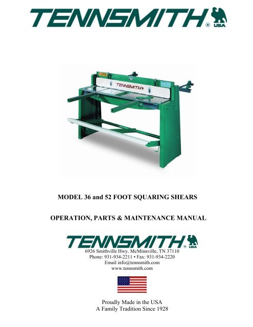
<strong>MODEL</strong> <strong>36</strong> <strong>and</strong> <strong>52</strong> <strong>FOOT</strong> <strong>SQUARING</strong> <strong>SHEARS</strong><br />
<strong>OPERATION</strong>, PARTS & MAINTENANCE MANUAL<br />
6926 Smithville Hwy. McMinnville, TN 37110<br />
Phone: 931-934-2211 • Fax: 931-934-2220<br />
Email info@tennsmith.com<br />
www.tennsmith.com<br />
Proudly Made in the USA<br />
A Family Tradition Since 1928
Model <strong>36</strong> <strong>and</strong> <strong>52</strong> Foot Squaring Shear Parts View<br />
2
Model <strong>36</strong> <strong>and</strong> <strong>52</strong> Parts List<br />
INDEX<br />
NO. <strong>36</strong> <strong>52</strong> DESCRIPTION QTY.<br />
1 10101 10151 TABLE 1<br />
2 10102 101<strong>52</strong> CUTTER BAR 1<br />
3 10103 10153 HOLDDOWN 1<br />
4 10051 10051 R.H. SIDE PANEL 1<br />
5 100<strong>52</strong> 100<strong>52</strong> L.H. SIDE PANEL 1<br />
6 10053 10053 FRONT ARM EXT. 2<br />
7 05055 05055 SCREW, FRONT ARM EXT. 4<br />
8 05673 05673 WASHER, FRONT ARM EXT. 4<br />
9 10054 10054 SPRING, HOLDDOWN 2<br />
10 10111 10164 STUD, HOLDDOWN SPRING 2<br />
11 05880 05880 NUT, HOLDDOWN STUD 2<br />
12 05907 05907 CAP NUT, HOLDDOWN STUD 2<br />
13 05060 05060 SCREW, HOLDDOWN 2<br />
14 05673 05673 WASHER, HOLDDOWN SCREW 2<br />
17 10055 10055 SCALE, L.H. TABLE 1<br />
18 10056 10056 SCALE, R.H. TABLE 1<br />
19 05021 05021 SCREW, TABLE SCALE 4<br />
20 05639 05639 WASHER, TABLE SCREW 4<br />
21 05327 05327 SET SCREW, TABLE ADJ. 2<br />
22 05035 05035 SCREW, TABLE LOCK 2<br />
23 05670 05670 WASHER, TABLE LOCK SCREW 4<br />
24 05075 05075 BOLT, TABLE 4<br />
25 05676 05676 WASHER, TABLE BOLT 4<br />
26 05925 05925 NUT, TABLE 4<br />
27 10105 10155 KNIFE, UPPER 1<br />
28 05033 05033 SCREW, UPPER KNIFE 7/9<br />
29 05670 05670 WASHER, UPPER KNIFE 14/18<br />
30 10106 10156 KNIFE, LOWER 1<br />
31 05035 05035 SCREW, LOWER KNIFE 6/8<br />
32 05670 05670 WASHER, LOWER KNIFE 12/16<br />
33 0<strong>52</strong>46 0<strong>52</strong>46 SET SCREW, LOWER KNIFE ADJ. 6/8<br />
34 05759 05759 NUT, LOWER KNIFE ADJ. 6/8<br />
35 10064 10064 SHIM, C’BAR 2<br />
<strong>36</strong> 0<strong>52</strong>49 0<strong>52</strong>49 SCREW, C’BAR SHIM 6<br />
37 05762 05762 NUT, C’BAR SHIM SCREW LOCK 6<br />
38 10107 10157 STRAIGHTENER ROD, C’BAR 1<br />
39 05673 05673 WASHER, STRAIGHTENER ROD 3<br />
40 05787 05787 NUT, STRAIGHTENER ROD 3<br />
41 10112 10165 ADJ. SCREW, STRAIGHTENER ROD 1<br />
44 05331 05331 SET SCREW, BACKGAUGE ROD 2<br />
45 05331 05331 SET SCREW, HOLDDOWN LOCK 2<br />
46 10302 10302 SPRING, <strong>FOOT</strong> PEDAL 2<br />
47 15053 15053 SPRING GUIDE 2<br />
48 15057 15057 CAP, SPRING 4<br />
49 15055 15055 STUD, SPRING 2<br />
50 05787 05787 NUT, SPRING STUD 8<br />
51 10069 10069 LINKAGE BOLT, C’BAR 2<br />
<strong>52</strong> 05827 05827 NUT, LINKAGE BOLT, C’BAR 2<br />
54 05826 05826 NUT, STUD 8<br />
55 10071 10071 TURNBUCKLE 2<br />
56 10073 10073 LINK, PEDAL 4<br />
57 06354 06354 PIN, LINKAGE, MOUNTING 2<br />
62 10058 10058 ROD, BACKGAUGE 2<br />
63 10110 10163 STOP, BACKGAUGE 1<br />
64 10065 10065 R. EXT. BAR, BACKGAUGE 1<br />
65 10066 10066 L. EXT. BAR, BACKGAUGE 1<br />
66 10059 10059 ADJ. BLOCK, BACKGAUGE 2<br />
67 10060 10060 ADJ. DIAL, BACKGAUGE 2<br />
68 10075 10075 ADJ. SCREW, BACKGAUGE 2<br />
69 05762 05762 NUT, ADJ. SCREW 2<br />
70 10061 10061 LOCK SCREW, BACKGAUGE 4<br />
71 10062 10062 ADJ. BRKT. BACKGAUGE 2<br />
72 05027 05027 SCREW, EXT. BAR 2<br />
73 05325 05325 SWIVEL BOLT 3<br />
74 10109 05765 NUT, SWIVEL BOLT 2<br />
75 10159 10159 STOP, FRONT MATERIAL 1<br />
76 10074 10074 “T”-NUT 3<br />
77 05938 05938 WING NUT, “T”-NUT 3<br />
78 10063 10063 BEVEL GAUGE 1<br />
80 10108 10158 BACKGAUGE ASSEMBLY 1<br />
3
FOREWORD<br />
This manual has been prepared for the owner <strong>and</strong> operators of the TENNSMITH Model <strong>36</strong> <strong>and</strong> <strong>52</strong> Shears.<br />
Its purpose, aside from operation instruction, is to promote safety through the use of accepted operating procedures.<br />
Read all instructions thoroughly before operating your shear.<br />
Also contained in this manual is the parts list for your shear. It is recommended that only TENNSMITH factory<br />
authorized parts be used for replacement parts.<br />
WARRANTY<br />
Your shear has a three year limited warranty from the date of purchase. The terms of the warranty are stated on the<br />
warranty registration card shipped with your machine. Please complete <strong>and</strong> return this card to activate your warranty.<br />
SAFETY INSTRUCTIONS<br />
1. Know the safety <strong>and</strong> operating instructions contained in this manual prior to operation of this shear. Become<br />
familiar with <strong>and</strong> underst<strong>and</strong> the hazards <strong>and</strong> limitations of this shear. Always practice safety.<br />
2. Wear approved eye safety protection, such as safety glasses or goggles, etc., when operating the shear to<br />
protect your eyes.<br />
3. Protective type footwear should be worn, <strong>and</strong> jewelry such as rings, watches, necklaces, etc., should be<br />
removed prior to operation of this shear.<br />
4. Do not remove the front hold-down guard (Index # 3). This is a protective device. If<br />
the hold-down is inoperable, immediately disconnect the power <strong>and</strong> lock the main<br />
power to the machine, <strong>and</strong> contact Tennsmith or your authorized distributor for a<br />
replacement part.<br />
5. Keep the hold-down (Index #3) at the minimum gap required to feed the material into<br />
the shear. The gap should never be higher than 3/16” from the table. If you have questions<br />
regarding the Hold-down, please consult the factory.<br />
6. Always keep h<strong>and</strong>s clear of the blade.<br />
7. Do not misuse the shear by using it for other than its intended purpose.<br />
8. Never exceed the rated capacity of this machine.<br />
9. Keep the work area clear <strong>and</strong> clean to avoid tripping or slipping.<br />
10. Any malfunction or abnormality pertaining to this machine should be reported to the maintenance supervisor<br />
immediately.<br />
4
RECEIVING THE SHEAR<br />
Examine the shear <strong>and</strong> accessories package for evidence of any possible damage sustained during transit. Any<br />
damage should be reported to your distributor immediately.<br />
INSTALLING THE SHEAR<br />
Carefully remove the shear from the shipping pallet. Locate the shear in a well-lighted area on a solid level floor. Use<br />
lag screws or bolts with exp<strong>and</strong>able shields or similar holding devices through the mounting feet, located on the bottom<br />
of the side panels.<br />
Place an accurate machinist level on the table top, <strong>and</strong> check the level of the machine in both directions. Use metal<br />
shims between the floor <strong>and</strong> the shear mounting surface to adjust the level. After the machine is level, tighten the<br />
mounting bolts.<br />
Periodically, recheck the unit for levelness.<br />
NOTE: Proper levelness greatly affects the performance of your shear, it is very important to<br />
ensure your machine is level prior to operation.<br />
<strong>OPERATION</strong> INSTRUCTIONS<br />
The mild steel capacity of the Model <strong>36</strong> <strong>and</strong> <strong>52</strong> shear is 16gauge. Included in the manual is a st<strong>and</strong>ard shearing,<br />
bending, <strong>and</strong> forming conversion chart for various materials including Aluminum, Stainless, <strong>and</strong> Plastics. If you have<br />
any capacity related questions on materials that do not appear on the chart, please contact Tennsmith technical support<br />
to help determine the exact capacity ratings.<br />
NEVER ATTEMPT TO SHEAR ANY MATERIAL GREATER THAN THE MAXIMUM RATING FOR<br />
YOUR SHEAR.<br />
The <strong>36</strong> <strong>and</strong> <strong>52</strong> is a fixed angle designed machines. Reducing the maximum width of your material does not increase<br />
the capacity rating of this shear.<br />
Never attempt to shear any material which would be less than a ½” cut across the full length<br />
of the table under full capacity.<br />
BLADE GAP ADJUSTMENT<br />
The factory setting for the gap between the upper <strong>and</strong> lower blade is .002. This setting was achieved using a piece of<br />
shim stock. However, if this is unavailable, the thickness of news print will approximate this dimension. The factory<br />
setting is the optimal clearance for the entire range of material likely to be sheared on this machine. Different materials<br />
<strong>and</strong> thickness may require a larger or slightly smaller clearance. If you have any specific questions regarding optimal<br />
blade gap, please consult Tennsmith.<br />
To begin, loosen the four bolts (24) securing the table (1) to the side panels (4, 5). Pull the table towards you <strong>and</strong><br />
depress the foot pedal (79) fully. St<strong>and</strong>ing on the foot pedal, start on the left h<strong>and</strong> side (facing) of the shear by snugging<br />
the table bolts. Next, insert the shim stock between the upper <strong>and</strong> lower blades. Tighten the table adjusting screw (21)<br />
until the shim is held fast between the blades. Then, keeping upward tension on the shim stock, progressively tighten<br />
the table locking screw (22) until the shim stock is freed of pressure <strong>and</strong> can be removed. Retighten the table bolts <strong>and</strong><br />
repeat the procedure on the opposite side of the shear.<br />
5
After completing alignment, check the entire length of the blades for proper clearance using your shim stock. You may<br />
find that you either have too much or not enough clearance in the center of the blades. This adjustment is accomplished<br />
by increasing or decreasing pressure on the bow adjustment bolt (41) located at the rear of the cutter bar.<br />
Note: A properly aligned shear will produce a scissor like sound when the blades transcend <strong>and</strong> will leave a<br />
minimal burr on sheared stock.<br />
CUTTER BAR ADJUSTMENT<br />
The cutter bar (2) should move freely throughout its range of travel without binding. This should be the case with a new<br />
shear. If the shear does bind, recheck for levelness.<br />
The gibbs should adjusted for snug yet nonbinding movement. To accomplish this, loosen all six gibb screws (<strong>36</strong>).<br />
Beginning at the right h<strong>and</strong> side of the shear, depress the foot pedal fully <strong>and</strong> lock the center gibb screw so that the<br />
cutter bar remains down. Then, gradually loosen the screw until the cutter bar returns to its upright position. Proceed to<br />
back the screw off an additional quarter turn <strong>and</strong> lock the jam nut (37) in place. Continue by repeating this procedure for<br />
the remaining gibb screws.<br />
Cutter bar lift is controlled by the amount of pressure exerted by the pedal springs (46). Appropriate tension was applied<br />
to the springs at the factory. However, over a period of years the springs may fatigue slightly <strong>and</strong> require additional<br />
compression.<br />
LINKAGE ADJUSTMENT<br />
The linkage on your TENNSMITH shear is comprised of two turnbuckle assemblies (55). Rotation of the turnbuckles is<br />
the means by which blade rake <strong>and</strong> pedal height is set. There should be no need for this adjustment on a new shear.<br />
Rake angle settings:<br />
<strong>MODEL</strong> <strong>36</strong><br />
Use a marker to mark the shear bed 2 inches to the from the right side edge of the table. Next, measure over 32 inches<br />
from the right side edge of the table <strong>and</strong> make another mark. Starting at the right h<strong>and</strong> side (facing the machine) at the<br />
designated mark on the table, rotate the turnbuckle (55) until the distance between the top <strong>and</strong> bottom blades is<br />
approximately 3/8 of an inch. At the opposing end, repeat the procedure allowing 1 ¾ inches clearance between the<br />
upper <strong>and</strong> lower blades. After you have the desired clearance between the upper <strong>and</strong> lower blades slightly adjust the<br />
turnbuckles so that they have an equal amount of tension. That is, if one turnbuckle has more play or lost motion in it<br />
than the other, it should be readjusted accordingly. Once the rake has been set <strong>and</strong> equal tension verified between the<br />
turnbuckles, retighten the jam nuts (54) <strong>and</strong> lock the turnbuckles in place.<br />
<strong>MODEL</strong> <strong>52</strong><br />
Use a marker to mark the shear bed 2 inches to the from the right side edge of the table. Next, measure over 48 inches<br />
from the right side edge of the table <strong>and</strong> make another mark. Starting at the right h<strong>and</strong> side (facing the machine) at the<br />
designated mark on the table, rotate the turnbuckle (55) until the distance between the top <strong>and</strong> bottom blades is<br />
approximately 3/8 of an inch. At the opposing end, repeat the procedure allowing 1 ¾ inches clearance between the<br />
upper <strong>and</strong> lower blades. After you have the desired clearance between the upper <strong>and</strong> lower blades slightly adjust the<br />
turnbuckles so that they have an equal amount of tension. That is, if one turnbuckle has more play or lost motion in it<br />
than the other, it should be readjusted accordingly. Once the rake has been set <strong>and</strong> equal tension verified between the<br />
turnbuckles, retighten the jam nuts (54) <strong>and</strong> lock the turnbuckles in place.<br />
6
<strong>FOOT</strong> PEDAL ADJUSTMENT: Foot pedal lift is similarly adjusted through turnbuckle rotation. Lift adjustment serves two<br />
purposes. It facilitates an acceptable working height for pedal operation <strong>and</strong> insures proper blade penetration across the<br />
working length of the shear. First, secure the top gibb screw on each side of the shear to maintain the blade rake angle.<br />
Then, adjust the foot pedal to what would appear to be an appropriate return lift.<br />
NOTE: When gibbs are loosened a slight degree of additional lift will be achieved.<br />
Once you have an approximate setting, loosen the top two gibb screws <strong>and</strong> depress the foot pedal. Examine the L.H.<br />
side of the machine to determine that the top blade does indeed transcend the bottom blade by at least 1/8 of an inch. If<br />
this is the case, tighten the jam nuts on the turnbuckles themselves or your rake alignment will be distorted. Should the<br />
penetration be less than satisfactory, retighten the gibbs to maintain rake <strong>and</strong> adjust the turnbuckles for additional pedal<br />
lift. This will allow for deeper penetration. Reverse the procedure for opposite circumstances.<br />
When adjusting the turnbuckles, be certain that both linkages have the same amount of tension applied to each. That is,<br />
if one turnbuckle has more play or lost motion in it than the other, it should be readjusted accordingly.<br />
As an additional point, it should be noted that there are two leverage holes provide in the foot pedal arms for connecting<br />
the linkage assembly. Your shear was shipped with the pins in the uppermost holes <strong>and</strong> should supply adequate<br />
leverage for shearing material within the machine’s rated capacity. However, if you will be operating the shear at its peak<br />
capacity, moving the linkage pins to the lower of the two holes will give you some additional leverage.<br />
HOLD-DOWN ADJUSTMENT<br />
CAUTION: THIS SHEAR SHOULD NOT BE OPERATED WITHOUT THE HOLDDOWN IN<br />
PLACE AND PROPERLY ALIGNED. The hold-down (3) is designed to engage the material before the blades<br />
yet allow only minimal clearance between the guard’s feet <strong>and</strong> the table surface. The gap between the hold-down<br />
feet <strong>and</strong> table surface should never be above 3/16” of an inch. The gap between the hold-down <strong>and</strong> the table is<br />
controlled by turning the nut on the hold-down studs (11). Clockwise rotation will increase clearance; counter clockwise<br />
turns will decrease the gap.<br />
The guard should be held snug against the milled pads on the cutter bar <strong>and</strong> not feel loose. You must be careful,<br />
however, that the hold-down bolts (13) are not so tight as to bind the guard when the cutter bar is in the down position.<br />
Properly aligned, the bolts will snug but still allow rotation of the hold-down screw washers (14). At the rear of the cutter<br />
bar you will find two tapped holes wherein hold-down jam screws (45) are located. Once you have applied proper<br />
tension to the hold-down screws, tighten the jam screws to lock alignment in place. (Note: The milled pads on the front<br />
<strong>and</strong> rear of the hold-down should be greased periodically to maintain proper action.<br />
BACK GAUGE ADJUSTMENT<br />
Slide back gauge rods (62) through the adjustment blocks (66) <strong>and</strong> brackets (71). Mount the rods in the holes found at<br />
the rear of the cutter bar. Move the gauge angle (63) up the rods until it contacts with the lower blade. Observe the<br />
pointers attached to the adjustment blocks <strong>and</strong> adjust the rods in or out until the embossed scales read zero on the<br />
pointers. Tighten the set screws (44) to lock the rods in place.<br />
To attain a particular setting, loosen the four lock screws (70) <strong>and</strong> slide the gauge to an approximate position. Fine tune<br />
adjustments are accomplished by locking the screws of the two adjustment brackets (71) while keeping those of the<br />
blocks (66) loose. The adjustment dial (68) can then be used to position the gauge in or out.<br />
7
SHARPENING BLADES<br />
Your TENNSMITH shear features “Tri-Action” ground blades. The upper blade has two cutting edges which are ground<br />
with a 2 degree edge relief. The upper blade can be turned over to expose the new cutting edge. It can be sharpened<br />
on a surface grinder by grinding both wide sides to the blade. The lower blade has one cutting edge with a 2 degree<br />
cutting edge relief <strong>and</strong> a 1 degree face relief. It can be sharpened on a surface grinder by grinding the wide side of the<br />
blade having the 1 degree relief. See Figure 2). Blade sharpening service is available from the factory.<br />
8
Maximum shearing capacity, mild steel<br />
Maximum shearing capacity, stainless steel<br />
Maximum cutting length<br />
Back gauge range<br />
Front gauge range<br />
Floor space, gauges in position<br />
Overall dimensions, less gauges, LxWxH<br />
Shipping weight<br />
Maximum shearing capacity, mild steel<br />
Maximum shearing capacity, stainless steel<br />
Maximum cutting length<br />
Back gauge range<br />
Front gauge range<br />
Floor space, gauges in position<br />
Overall dimensions, less gauges, LxWxH<br />
Shipping weight<br />
MACHINE SPECIFICATIONS<br />
Model <strong>36</strong><br />
16 gauge / 1,6mm<br />
20 gauge / 1,0mm<br />
<strong>52</strong>-1/4 in. / 1327mm<br />
30 in. / 762mm<br />
37 in. / 940 mm<br />
45 x 80 in. / 1143 x 2032 mm<br />
46-1/4 x 24 x 42 in. / 1181 x 686 x 1067 mm<br />
700 lbs. / 317.5 kg<br />
Model <strong>52</strong><br />
16 gauge / 1,6mm<br />
20 gauge / 1,0mm<br />
<strong>52</strong>-1/4 in. / 1327mm<br />
30 in. / 762mm<br />
37 in. / 940 mm<br />
60 x 80 in. / 1<strong>52</strong>4 x 2032 mm<br />
61 x 25 x 42 in. / 1550 x 915 x 1067 mm<br />
950 lbs. / 431 kg<br />
APPROXIMATE SHEARING, BENDING AND FORMING<br />
CAPCITIES FOR VARIOUS MATERIALS COMPARED TO MILD STEEL<br />
Mild Steel Capacity 20ga. 18ga. 16ga. Mild Steel Capacity 20ga. 18ga. 16ga.<br />
NON-FERROUS METALS<br />
FERROUS METALS<br />
Aluminum Iron-dead soft 20ga. 18ga. 16ga.<br />
1100-0, 2024-0 .070 .090 .125 Steel low carbon<br />
50<strong>52</strong>-0. 6061-T4 .070 .090 .125 1074, 1095 C.R. Spring Steel 24ga. 22ga. 20ga.<br />
2024-T3, 50<strong>52</strong>-H34 .048 .063 .090 Hot Rolled 20ga. 18ga. 16ga.<br />
5086-H<strong>36</strong>, 6061-T6 .048 .063 .090 Low carbon Cold Rolled 20ga. 18ga. 16ga.<br />
Copper <strong>and</strong> Alloys Stainless Steel Annealed 24ga. 22ga. 20ga.<br />
Electrolytic Copper 18ga. 16ga. 14ga. OTHER MATERIALS<br />
Bronze Commercial 18ga. 16ga. 14ga. Plastics<br />
Brass 70-30 18ga. 16ga. 14ga. ABS Compounds .120 .150 .200<br />
Nickel Alloys Polycarbonate .075 .105 .125<br />
Inconel 600 24ga. 22ga. 20ga. Printed Circuit Boards<br />
Monel R405 24ga. 22ga. 20ga. Copper-Clad<br />
Nickel 200A Annealed 24ga. 22ga. 20ga. Epoxy Laminate .086 .115 .150<br />
Zinc as Rolled 20ga. 18ga. 16ga.<br />
Approximate Gauge Equivalents<br />
Gauge 28 26 24 22 20 18 16 14 12 11 10<br />
Inches .015 .018 .024 .030 .0<strong>36</strong> .048 .060 .075 .105 .120 .135<br />
Millimeters .38 .46 .61 .76 1.00 1.25 1.60 2.00 2.70 3.05 3.50<br />
6926 Smithville Hwy. McMinnville, TN 37110<br />
Phone: (931) 934-2211 • Fax (931) 934-2220<br />
Email: info@tennsmith.com<br />
www.tennsmith.com<br />
9