Machine Manual - Production Tool Supply
Machine Manual - Production Tool Supply
Machine Manual - Production Tool Supply
You also want an ePaper? Increase the reach of your titles
YUMPU automatically turns print PDFs into web optimized ePapers that Google loves.
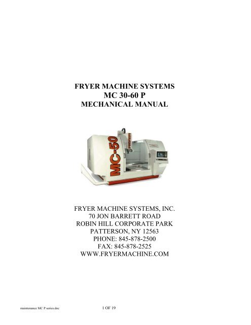
FRYER MACHINE SYSTEMS<br />
MC 30-60 P<br />
MECHANICAL MANUAL<br />
FRYER MACHINE SYSTEMS, INC.<br />
70 JON BARRETT ROAD<br />
ROBIN HILL CORPORATE PARK<br />
PATTERSON, NY 12563<br />
PHONE: 845-878-2500<br />
FAX: 845-878-2525<br />
WWW.FRYERMACHINE.COM<br />
maintenance MC P series.doc 1 OF 19
MECHANICAL DRAWINGS ......................................................................................................................................................3<br />
HEAD ASSEMBLY..................................................................................................................................................................4<br />
CAROUSEL TOOL CHANGER ..............................................................................................................................................5<br />
ARM TOOL CHANGER ..........................................................................................................................................................6<br />
Z AXIS COLUMN ....................................................................................................................................................................8<br />
X AXIS TABLE........................................................................................................................................................................9<br />
BASE.......................................................................................................................................................................................10<br />
MC SHEET METAL...............................................................................................................................................................11<br />
RETENTION STUD ...............................................................................................................................................................12<br />
Leveling Procedure For VB or MC <strong>Machine</strong>s.............................................................................................................................13<br />
High Pressure Coolant System ....................................................................................................................................................16<br />
maintenance MC P series.doc 2 OF 19
maintenance MC P series.doc 3 OF 19<br />
MECHANICAL DRAWINGS
maintenance MC P series.doc 4 OF 19<br />
HEAD ASSEMBLY
maintenance MC P series.doc 5 OF 19<br />
CAROUSEL TOOL CHANGER
ARM TOOL CHANGER<br />
NOTE 1 OIL CUP<br />
NOTE 2 SOLENOID VALVE<br />
NOTE 1:<br />
OIL CUP SHOULD BE<br />
CHECKED MONTHLY<br />
FILL AS NEEDED WITH<br />
HYDRAULIC OIL<br />
FILL CUP HALF WAY<br />
NOTE 2:<br />
SOLENOID VALVE FUNCTIONS<br />
1.POT UP 2.POT DOWN<br />
3.ARM ORIGIN 4.ARM 60°<br />
5.ARM UP 6.180° & DOWN<br />
maintenance MC P series.doc 6 OF 19
ARM TOOL CHANGER<br />
NO PART NO. DESCRIPTION SPECIFICATIONS QTY<br />
1 Arm Assembly 1<br />
2 Pot 24<br />
3 Carousel Motor 220 VAC 200W 1<br />
4 Soleniod 6<br />
5 Limit Switch 1<br />
6 Proximity Sensor 2<br />
7 Air cylinder Arm up & down 1<br />
8 Air cylinder Pot up & down 1<br />
9 Proximity Switch on pot up/down cylinder 2<br />
10 Air cylinder 60 deg.cylinder ass. 1<br />
11 Air cylinder 180 deg. cylinder ass. 1<br />
maintenance MC P series.doc 7 OF 19
Z AXIS COLUMN<br />
<br />
<br />
<br />
<br />
<br />
<br />
<br />
<br />
<br />
<br />
<br />
<br />
<br />
<br />
<br />
<br />
<br />
<br />
<br />
<br />
<br />
<br />
<br />
<br />
<br />
<br />
<br />
<br />
<br />
<br />
<br />
<br />
<br />
<br />
<br />
<br />
<br />
<br />
<br />
<br />
<br />
<br />
<br />
<br />
<br />
<br />
<br />
maintenance MC P series.doc 8 OF 19
X AXIS TABLE<br />
49<br />
1<br />
50<br />
9<br />
51<br />
2<br />
52<br />
3<br />
10<br />
11<br />
6<br />
13<br />
15<br />
16<br />
12<br />
7<br />
14<br />
47<br />
4<br />
8<br />
46<br />
48<br />
45<br />
18<br />
44<br />
5<br />
19<br />
39<br />
43<br />
42<br />
28<br />
30<br />
40<br />
29 31<br />
41<br />
32<br />
20<br />
33<br />
35<br />
22<br />
34<br />
36<br />
23<br />
21<br />
24<br />
38<br />
37<br />
26<br />
27<br />
25<br />
maintenance MC P series.doc 9 OF 19
maintenance MC P series.doc 10 OF 19<br />
BASE
maintenance MC P series.doc 11 OF 19<br />
MC SHEET METAL
FRYER PART NUMBERS<br />
CAT 40<br />
TOL-5450<br />
BT 40<br />
TOL-5456<br />
CAT 50<br />
TOL-5454<br />
NOTE:<br />
IF THRU COOLANT IS NEEDED, PLEASE CALL FOR PROPER<br />
PART NUMBER<br />
RETENTION STUD<br />
maintenance MC P series.doc 12 OF 19
Leveling Procedure For VB or MC <strong>Machine</strong>s<br />
When leveling a machine with more than 6 leveling pads, care must be taken to not twist the base<br />
of the machine. This procedure will review the proper steps to level successfully.<br />
<strong>Tool</strong>s required – 12” .0005 per foot level, & 32 mm (1.25) wrench<br />
Estimated time – VB 1 to 2 hrs, MC 2 to 3 hrs<br />
Step 1<br />
With the table centered, level the machine’s four outside pads. Be sure that the center pads are<br />
not touching, and all four outside pads have load. Also check to make sure that the machine’s casting is<br />
not touching the floor.<br />
Place level in<br />
center of<br />
table<br />
Adjust four pads<br />
Step 2<br />
Bring four inside pads down till they are just touching.<br />
maintenance MC P series.doc 13 OF 19
Step 3<br />
Move table to the front of the travel, and level the four front pads. The majority of adjustment<br />
should be on the two middle pads. Once level is achieved, verify all four pads have load.<br />
Two center pads<br />
Step 4<br />
Now move the table to the rear and adjust the final two leveling pads. Once level is achieved,<br />
verify all eight pads have load<br />
Final pads<br />
maintenance MC P series.doc 14 OF 19
Step 5<br />
Now that the machine should be level, jog the Y-axis back and forth to verify that level is<br />
consistent. If it is still out, slowly adjust pads to achieve level thru the travel of the machine.<br />
Jog machine<br />
Step 6<br />
The final check to be performed is traming of the head. Over a 12” diameter circle you must be<br />
within .0005 total indicator reading.<br />
3<br />
1.<br />
TABLE<br />
SWEEP<br />
1 2<br />
.0005”<br />
OVER 12” DIAMETER<br />
IN X-Y AXIS<br />
2.<br />
0<br />
3.<br />
maintenance MC P series.doc 15 OF 19
High Pressure Coolant System<br />
Component description and service procedures<br />
Low pressure tank - this component<br />
holds the coolant filter and supplies<br />
the hi pressure pump.<br />
Input feed from the coolant tank.<br />
Transfer pump – supplies coolant to<br />
the low pressure tank, as well as the<br />
standard flood coolant system.<br />
This pump is not self-priming. Only<br />
prime if coolant tank is full<br />
High pressure pump – supplies<br />
the high pressure thru spindle<br />
coolant only when turned on<br />
separate from flood coolant.<br />
MC max pressure 1000psi<br />
VB max pressure 300psi<br />
maintenance MC P series.doc 16 OF 19
High pressure pump adjuster –<br />
this is preset from the factory,<br />
and do not recommend changing<br />
High pressure gauge – will only<br />
display reading if there is<br />
sufficient backpressure.<br />
Tank pressure gauge – will<br />
display 30 to 35psi with a new<br />
filter installed. You must<br />
replace the filter if pressure<br />
exceeds 50psi.<br />
Tank pressure relief valve – use<br />
to bleed excess air out of the<br />
tank after replacing the coolant<br />
filter.<br />
maintenance MC P series.doc 17 OF 19
Do not open if drivers<br />
are powered on.<br />
<strong>Machine</strong> must be in<br />
E-stop.<br />
Filter replacement should be performed if the tank pressure gauge exceeds 50psi. You may also<br />
experience a high-pressure coolant fault on the cnc control. If this fault occurs check the pressure first.<br />
Filter replacement procedure<br />
1. Place machine in e-stop<br />
2. Open ball valve to insure the tank has no pressure.<br />
3. Open top lid of the tank and remove the filter.<br />
4. Discard filter (filter is not reusable)<br />
5. Insert new filter and use installation tool to push the filter down until you feel it snap into place.<br />
6. Close the tank lid and ball valve<br />
7. Now turn on the drives and coolant option<br />
8. You will need to bleed the tank with the ball valve while the high pressure thru spindle coolant is<br />
running<br />
9. Now you should be able to continue machine operation.<br />
maintenance MC P series.doc 18 OF 19
Fill point for pump oil -<br />
Replace hydraulic oil<br />
once a year.<br />
If you are using the<br />
machine more than a<br />
typical 40 hr work<br />
week, change oil more<br />
frequently.<br />
Drain plug for pump oil<br />
maintenance MC P series.doc 19 OF 19
FRYER MACHINE SYSTEMS<br />
ELECTRICAL &<br />
PROCEDURES MANUAL<br />
ANILAM 6000i CONTROL<br />
FRYER MACHINE SYSTEMS, INC.<br />
70 JON BARRETT ROAD<br />
ROBIN HILL CORPORATE PARK<br />
PATTERSON, NY 12563<br />
PHONE: 845-878-2500<br />
FAX: 845-878-2525<br />
WWW.FRYERMACHINE.COM<br />
Electrical <strong>Manual</strong> Anilam 6000i.doc Page 1 of 25
Maintenance <strong>Manual</strong> Electrical and Procedure Section for Anilam 6000i control<br />
Table of Contents<br />
Safety Rules……………………………………………………………………………………….Page 3<br />
Startup Procedure………………………………………………………………………………….Page 4<br />
Startup Report……………………………………………………………………………………..Page 6<br />
Electrical Panel Layout……………………………………………………………………………Page 8<br />
External Transformer wiring………………………………………………………………………Page 9<br />
Pneumatic Arm ATC adjustment and repair………………………………………………………Page 11<br />
Carousel ATC details………………………………………………………………………………Page 16<br />
Coolant system connections……………………………………………………………………….Page 21<br />
Anilam 6000i M codes…………………………………………………………………………….Page 22<br />
Maintenance schedule……………………………………………………………………………...Page 23<br />
Renishaw tool probe installation…………………………………………………………………..Page 24<br />
Optional Spindle chiller details……………………………………………………………………Page 25<br />
Electrical Schematics………………………………………………………………………………Page 26<br />
Electrical <strong>Manual</strong> Anilam 6000i.doc Page 2 of 25
SAFETY RULES<br />
READ BEFORE OPERATING MACHINE<br />
1. PREVENT LOOSE CLOTHING, HAIR, JEWELRY FROM CONTACTING SPINDLE<br />
2. NEVER: CHANGE TOOLS, HANDLE SPINDLE, CHANGE PARTS OR PERFORM WORK<br />
ON MILL UNLESS CNC IS IN EMERGENCY STOP OR TOOL CHANGE MODES<br />
3. ALWAYS WEAR EYE PROTECTION WHEN OPERATING MILL.<br />
4. DO NOT OPERATE MILL WITHOUT AXIS MOTOR COVERS OR AXIS WAY COVERS IN<br />
PLACE.<br />
5. DO NOT PLACE OBJECTS OR HANDS BETWEEN COLUMN AND TABLE/SADDLE<br />
ASSY, UNLESS CNC IS IN EMERGENCY STOP POSITION.<br />
6. DO NOT MODIFY EQUIPMENT WITHOUT APPROVAL FROM FRYER MACHINE<br />
SYSTEMS. DOING SO MAY VOID YOUR WARRANTY.<br />
7. ELECTRICAL ENCLOSURES CONTAIN HIGH VOLTAGE. DISCONNECT EQUIPMENT<br />
FROM POWER SOURCE BEFORE OPENING CABINETS.<br />
8. CHECK LUBRICANT FILL LEVELS BEFORE OPERATING.<br />
9. DO NOT OPERATE POWER DRAWBAR UNIT WHILE SPINDLE IS IN MOTION.<br />
10. EMERGENCY STOP MILL WHEN NOT IN USE<br />
11. KEEP VISES, CLAMPS, FIXTURE OR WORKPIECE FROM EXTENDING BEYOND BACK<br />
EDGE OF TABLE.<br />
12. TURN OFF POWER IF:<br />
POWER PROBLEMS DEVELOP<br />
IN THE EVENT OF ELECTRICAL STORMS.<br />
AMBIENT TEMPERATURES EXCEED 105 DEGREES FARENHEIT.<br />
Electrical <strong>Manual</strong> Anilam 6000i.doc Page 3 of 25
STARTUP PROCEDURE FOR FRYER VB/MC SERIES MILLS<br />
WITH ANILAM 6000i CONTROLLERS<br />
Unpack <strong>Machine</strong>:<br />
1. Remove plastic wrap. Carefully inspect for any damage.<br />
2. Install leveling pads and level machine. (This is usually the responsibility of the rigger or<br />
customer)<br />
Assistance will be necessary to perform the following steps:<br />
3. Using a socket or suitable wrench (Pliers are not recommended) turn the Z ballscrew<br />
clockwise from the top of the screw enough to remove wooden shipping block on table. Be<br />
careful not to let the ratchet/wrench slip backwards.<br />
4. Turn the ratchet/wrench counter clockwise until counterweight chains are taut, and<br />
counterweight bar is free<br />
5. Remove counterweight bar. At this time you must remove the ratchet/wrench otherwise<br />
serious damage could occur.<br />
6. Install the Z-Axis motor and drive belt, and any other items that may have been removed for<br />
shipping purposes. Make sure to align marks on direct drive coupling if equipped. Do not<br />
tighten motor locking bolts until motor is floated into center.<br />
7. Check that front panel with swivel arm is clear of Z-Axis head motion. (If equipped)<br />
8. Optional ATC: Remove the carousel support bolted to the table. Remove the locking orange<br />
bracket to prevent the carousel to slide back and fourth(mounted on rear of atc next to large<br />
air cylinder).<br />
Line voltage check:<br />
1. Verify 230/460 vac. (+/- 10%) is wired to the main disconnect correctly. (460vac. Optional).<br />
The factory configuration is stamped on the serial number plack. The transformer equipped<br />
with all 6000i controls has multiple taps, that should be configured for 400VAC at the control<br />
amplifier input. See documentation included with this manual.<br />
2. Check all wire connections, relays, contacts, and plugs to be sure nothing has come loose. If<br />
so, reseat or tighten before turning on main power.<br />
All voltage checks should be recorded on the STARTUP REPORT form.<br />
<strong>Machine</strong> power-up procedure:<br />
1. Turn the 230/460VAC disconnect switch rod on the electrical cabinet with a pair of pliers a ¼<br />
turn clockwise.<br />
2. Boot-up the control.<br />
3. Release the E-stop switch and press SERVO RESET to engage servo drives.<br />
Electrical <strong>Manual</strong> Anilam 6000i.doc Page 4 of 25
Voltage checks (All voltages +/- 10%):<br />
1. Check for 110vac: terminal strip #1 AC hot #2 AC neutral<br />
2. Check for 220 vac 3 phase: terminal strip #13- #14- #15<br />
3. Check for 400 vac 3 phase: terminal strip #L1-#L2-#L3<br />
4. Check for +24vdc: terminal strip #12=24 vdc #20=com<br />
Additional Checks:<br />
1. Make sure way surfaces are receiving sufficient oil from pump.<br />
2. Make sure air pressure to regulator-lubricator unit is set at 90 psi minimum.<br />
3. Check the tool change height and orient position.<br />
4. Check for proper phasing on all three phase motors. Especially arm style ATC carousel motor,<br />
flood pump, wash-down pump, chip auger, and spindle motor fan.<br />
All information should be recorded on a Fryer <strong>Machine</strong> Startup Form with any unusual conditions listed and returned to Fryer<br />
<strong>Machine</strong> Service Dept. If any problems are encountered or if you have any questions, please contact FRYER MACHINE<br />
SYSTEMS Service Department at (845) 878-2500.<br />
Electrical <strong>Manual</strong> Anilam 6000i.doc Page 5 of 25
70 Jon Barrett Road<br />
Robin Hill Corporate Park<br />
Patterson, N.Y. 12563<br />
Phone: (845) 878-2500<br />
Fax: (845) 878-2525<br />
E-mail: service@fryermachine.com<br />
STARTUP REPORT - ANILAM 6000i Control<br />
CUSTOMER__________________________DATE: ____________________<br />
MODEL #: ____________________ SERIAL #: _________________ CONTROL SN#: ____________________<br />
DISTRIBUTOR: _______________________________ SERVICE TECH: _________________________________<br />
SHOP CONTACT: __________________________________<br />
TITLE:___________________________________<br />
ATTENTION:<br />
ITEMS CAN BECOME LOOSE DURING SHIPPING CAUSING A LOSS OF CONNECTIONS. THIS MAY RESULT IN<br />
IMPROPER MACHINE FUNCTION AND/OR DAMAGE TO THE MACHINE OR COMPONENTS. BEFORE INITIAL<br />
POWER-UP:<br />
• TIGHTEN ALL SCREWS AND ELECTRICAL CONNECTIONS IN THE ELECTRICAL CABINET .<br />
• CHECK TO ENSURE THAT ALL ELECTRICAL COMPONENTS ARE PROPERLY SEATED AND SECURED.<br />
ELECTRICAL CONNECTIONS AND COMPONENTS CHECKED: _________<br />
ELECTRIAL CABINET<br />
220/440vac: ________<br />
(MAIN DISCONNECT SWITCH)<br />
110vac: ________ (tb#1- tb#2)<br />
400vac: ________ (tb#L1-tb#L2-tb#L3)<br />
24vdc: ________ (tb#12-tb#20)<br />
AIR PRESSURE: _________<br />
WAYLUBE PRESENT AT X, Y & Z BOX WAY SURFACES. __________<br />
HOUR METER READING ______________<br />
COUPLING ORIENTATION AND AXIS TRAVEL CHECKED _____________________<br />
INITIAL START-UP QUALITY SURVEY<br />
At Fryer <strong>Machine</strong> Systems, we strive to continuously improve the quality of our products and services.<br />
As a qualified machine tool technician, your feedback is an essential part of this ongoing process.<br />
Please take a moment to fill out the following information. It will be greatly appreciated.<br />
Please circle the appropriate response (1=worst, 5=best) for each question. Feel free to add any comments.<br />
Electrical <strong>Manual</strong> Anilam 6000i.doc Page 6 of 25
MISSING PARTS<br />
Were there any parts missing? ............................................................................................Yes No<br />
If yes, what was missing?<br />
____________________________________________________________________________<br />
____________________________________________________________________________<br />
____________________________________________________________________________<br />
INITIAL IMPRESSIONS<br />
Was machine received in satisfactory condition? ................................................................Yes No<br />
If no, what was lacking?<br />
____________________________________________________________________________<br />
____________________________________________________________________________<br />
____________________________________________________________________________<br />
Please rate the overall appearance of the machine: ............................................................1 2 3 4 5<br />
Comments:<br />
____________________________________________________________________________<br />
____________________________________________________________________________<br />
____________________________________________________________________________<br />
PERFORMANCE<br />
Please rate the mechanical systems of the machine: ..........................................................1 2 3 4 5<br />
____________________________________________________________________________<br />
____________________________________________________________________________<br />
____________________________________________________________________________<br />
Please rate the electrical systems of the machine: ..............................................................1 2 3 4 5<br />
Comments:<br />
____________________________________________________________________________<br />
____________________________________________________________________________<br />
____________________________________________________________________________<br />
SERVICE<br />
Were there any problems with the machine during start-up? ...............................................Yes No<br />
If yes, please list:<br />
____________________________________________________________________________<br />
____________________________________________________________________________<br />
____________________________________________________________________________<br />
What issues, if any, are still outstanding?<br />
____________________________________________________________________________<br />
____________________________________________________________________________<br />
____________________________________________________________________________<br />
Was our Service Dept. helpful during the start-up? Please rate us: .....................................1 2 3 4 5<br />
ADDITIONAL COMMENTS:<br />
_____________________________________________________________________________________________________<br />
_____________________________________________________________________________________________________<br />
_____________________________________________________________________________________________________<br />
Electrical <strong>Manual</strong> Anilam 6000i.doc Page 7 of 25
PANEL LAYOUT<br />
Electrical <strong>Manual</strong> Anilam 6000i.doc Page 8 of 25
Fryer Mill with Anilam 6000 and 20KVA Transformer<br />
Setup<br />
The Anilam 6000 control requires special secondary voltage of 400 vac. This requires a<br />
special transformer to be installed on all mills equipped with this control. The 20KVA<br />
transformer is used on all mills except ones with the 30 Horsepower spindle option. The<br />
transformer is pre-wired at the factory for the primary voltage specified at time of order<br />
and the machine serial number tag.<br />
Main input power must ONLY be connected to the line side (TOP) of the disconnect<br />
switch located inside the electrical cabinet. NEVER connect main power directly to the<br />
Transformer. Following is an explanation of how to configure the transformer (all wiring<br />
changes are done inside the transformer) for the two most common incoming primary<br />
voltage ranges. Refer to the specifications on the front cover of the transformer for other<br />
possible inputs (210 – 483 V).<br />
For 208-250 VAC input (Voltage must be within this range or warranty will be void.),<br />
connect the internal tap wires from H1-H2-H3 to each corresponding tap (4=250, 5=230,<br />
6=210) respectively (one wire per phase). The 3- 12 AWG black wires labeled as 13-14-<br />
15 should be connected to H1, H2, H3 respectively alongside with the input AC wires<br />
ONLY when 208 – 250 volt primary is used.<br />
For 420-495 VAC input (Voltage must be within this range or warranty will be void),<br />
connect the internal tap wires from H1-H2-H3 to each corresponding tap (1=483, 2=460,<br />
3=437) respectively (one wire per phase). The 3- 12 AWG black wires labeled as 13-14-<br />
15 should be connected to X1-13, X2-14, X3-15<br />
Electrical <strong>Manual</strong> Anilam 6000i.doc Page 9 of 25
Fryer Mill with Anilam 6000i Controls and 25KVA<br />
Transformer Setup<br />
The Anilam 6000 control requires special voltage of 400 volts AC. This requires a special<br />
transformer to be installed on all mills equipped with this control. The 25 KVA<br />
transformer is only used on mills equipped with the 30 HP spindle motor. The transformer<br />
is pre-wired at the factory for the primary voltage specified on the order and the machine<br />
serial number tag.<br />
Main input power is ALWAYS connected to the line side of the disconnect switch<br />
located inside the electrical cabinet. NEVER connect main power directly to Transformer<br />
wires.<br />
Following is an explanation of how to configure the transformer ( all wiring changes are<br />
done inside the transformer) for the two possible incoming voltage ranges.<br />
For 208-250 VAC input (Voltage must be within this range or warranty will be void.),<br />
connect the wires with white insulation from H1-H2-H3 to corresponding taps #2 on the<br />
transformer phase columns. The 12 AWG black wires labeled as 13-14-15 should be<br />
connected to H1, H2, H3 respectively along with the input AC wires.<br />
For 420-495 VAC input (Voltage must be within this range or warranty will be void),<br />
connect the wires with white insulation from H1-H2-H3 to corresponding taps #1 on the<br />
transformer phase columns. The 12 AWG black wires labeled as 13-14-15 should be<br />
connected to Y1, Y2, Y3 respect..<br />
Electrical <strong>Manual</strong> Anilam 6000i.doc Page 10 of 25
ATC Pneumatic Arm Operation and Repair with Anilam 6000i<br />
control<br />
ATC Operation Guidelines<br />
• Due to the complexity and timing of the ATC, it should only be operated with the M6 command.<br />
• Never interrupt the tool changer in the middle of cycle, wait for it to complete the tool change. If a low air alarm sets and<br />
the tool gets stuck in the spindle, then go to the recovery section on page 3 of this document.<br />
• This is a random access tool changer to reduce tool change time. The machine will always keep track of the correct tool even<br />
though it may not agree with the bin #. You can have the carousel move to the next tool requested with a T# command on a<br />
line by itself. When a tool change is specified (M6) this tool # will be loaded into the spindle.<br />
• If the t code is programmed on the same line as the M6 command make sure the M6 is before the T code (example: M6T4).<br />
• Most tools have a deeper notch on one side of the tools v-flange. The ATC carousel will only allow this deeper notch to fit into<br />
the carousel key. Make sure when installing tools in spindle this orientation is verified. After spindle orientation the key slot on<br />
the v-flange of the tool furthest from the operator will align with the key on the carousel.<br />
• The carousel motor is a 3 phase motor and must be phased correctly for proper direction. M58 will increase carousel position<br />
to next higher tool number. The machine is phased properly at the factory before shipment, so if carousel rotates wrong<br />
direction switch any two incoming power wires at disconnect. Make sure main power breaker is off!<br />
<strong>Manual</strong> operation of tool change solenoid valves<br />
If the tool changer gets hung up the solenoid valves can be operated manually to reset the tool changer. Here is a description<br />
of the operation of the valves. Access the air solenoid valves for the tool changer behind the door on the front of the ATC.<br />
There is a diagram of the operation of each solenoid. These can be run manually by depressing the blue manual override<br />
buttons. Make sure you push the buttons in sequence otherwise damage could be done to the ATC. There are three two way<br />
solenoid valves mounted horizontally. The top solenoid valve controls the carousel tool pot; left button returns tool pot to up<br />
position, right button drops pot down. The middle solenoid controls the arm movement 60° under the spindle and to normal<br />
rest position. The right button moves the arm under the spindle nose to grab a tool, left button moves the arm back to its<br />
normal clearance position. The bottom solenoid controls the arm down and 180° and arm up. The right button moves the arm<br />
down and then 180°, the left button returns the arm up.<br />
The proper sequence of a tool change and the respective M-codes is as follows:<br />
(Note that you will have to press the cycle start button twice to execute these commands)<br />
1. T-code to move carousel to pending tool<br />
2. M52 tool pot down<br />
3. M68 moves z axis to tool change position<br />
4. M60 spindle orient<br />
5. M62 Arm moves under spindle to grab tool and carousel pot<br />
6. M54 turns drawbar on<br />
7. M64 Arm removes tool from spindle and carousel tool pot and swaps them<br />
8. M65 arm up to install pending tool in spindle and old tool into carousel pot.<br />
9. M55 Drawbar off to grab tool in spindle.<br />
10. M63 Arm origin<br />
11. M53 carousel tool pot up<br />
Electrical <strong>Manual</strong> Anilam 6000i.doc Page 11 of 25
<strong>Tool</strong> Change Height Adjustment<br />
The proper tool change height must be set for the ATC to perform correctly. The tool change height (machine coordinates<br />
from home position) is stored in parameter NP_DG_TC_pos_Z_put_in. This will have to be checked if the home position is<br />
different due to removing the z motor or home switch or dog. Here is a procedure to set this height correctly: There is some<br />
allowance ( play ) allowed for the tool change height (about .03”) This is the difference between the v flange groove of the tool<br />
and the v location of the arm . You will see this vertical play if you install a tool into the arm when the machine is in e-stop.<br />
Make sure you do not leave the tool there!<br />
1. Home the machine.<br />
2. Move the z-axis to the tool change height with an M68 command in manual mode. The number is derived from the distance<br />
from home position (machine zero) to the proper height for tool change. To get to this parameter from manual mode:<br />
-Press shift<br />
-(F3) config<br />
-Password= 222 (may not be necessary if you already typed in the password)<br />
-(F6) config data<br />
-Now you will have to follow the directory tree by opening up each folder and edvancing into the proper subfolders. The<br />
path is a follows: System-PLC-cfgoemposition The parameter for tool change height is: NP_DG_TC_pos_z_put_in.<br />
That number is in MM (millimeters) and is a negative value. Change display to read in MM to get a direct read out in the<br />
<strong>Machine</strong> Coordinates box in Z =(ex. -62.408 MM)<br />
3. Orient the spindle with an M60 command.<br />
4. Install a tool in the spindle.<br />
5. Press the middle right solenoid manual button to grab the tool, see the description of manual solenoid operation.<br />
6. Look to see if the position of the z axis will cause the v flange groove of the tool is in the center of the arm v notch. Return the<br />
arm manually back out of way with the middle left button on the solenoid valve. Adjust the tool change height parameter<br />
outlined in step 2 and repeat until correct alignment is achieved.<br />
7. At this time you can alternate the middle left and middle right button to check for smooth engagement of the arm into and<br />
away from the tool. If the arm doesn’t respond smoothly then further z axis height adjustment may be required.<br />
Spindle Orient Adjustment<br />
1. With z axis at maximum positive limit and ATC arm under spindle nose (manual solenoid button 2 nd on right). Make sure<br />
spindle can be spun without spindle keys hitting ATC arm.<br />
2. Orient spindle with M60<br />
3. Look to see if spindle keys are in alignment with notch in the arm.<br />
4. In manual follow the steps below to get to the orient postion parameter:<br />
-Press shift<br />
-Password=222 (may not be necessary if you already typed in the password)<br />
-(F6) config data<br />
-Now you will have to follow the directory tree by opening up each folder and edvancing into the proper subfolders. The<br />
path is a follows: System-PLC-cfgoemposition The parameter for spindle orient position is: NP_DG_TC_pos_spindle<br />
5. Command M5 cycle start. This will turn off the orient command.<br />
6. Repeat steps 2 and 5 and adjust parameter until correct.<br />
Recovering From <strong>Tool</strong> Change Failure<br />
If the tool changer fails you may get an alarm “timeout in spindle sequence”, this means that after 30 seconds of waiting a<br />
function did not get it’s proper finish signal. You must look to see what function did not complete. It most likely had to do with<br />
movement of the arm. Look at the solenoid valves, the solenoid valve that is illuminated is the operation that failed. Press<br />
emergency stop. If the arm did not complete grabbing the tool, make sure the pot is down and then press the arm return<br />
manual button. Refer to manual operation of tool changer pneumatic solenoid valves. After the arm is returned to normal<br />
resting position, tool is removed from the spindle and carousel pot returned manually, the carousel pots may have to be reset.<br />
If the carousel does not rotate check the fuses in the electrical cabinet. Refer to electrical schematics in maintenance manual.<br />
Electrical <strong>Manual</strong> Anilam 6000i.doc Page 12 of 25
<strong>Tool</strong> Carousel Reset<br />
To reset all the tool bin locations follow this procedure.<br />
1. Remove tool from spindle<br />
2. In MDI command : M6T0 cycle start<br />
3. Remove any tool from spindle<br />
4. In MDI command : M61 cycle start ( this will index carousel to bin #1 )<br />
5. Go to tool table, soft key F9, and then press soft key F4 BIN. The bin numbers on the left hand side will be 0-#pots in<br />
carousel, set the tool number to the same as the bin number leaving bin 0 blank.<br />
6. Remove all tools from carousel and reinstall.<br />
Arm Alignment<br />
If the arm no longer moves in the proper angular alignment then an adjustment may<br />
be required. The arm is held in place on the arm shaft with a compression clamp.<br />
1. Install tool in spindle<br />
2. Orient spindle M60<br />
3. Install tool in carousel pot<br />
4. Drop carousel pot down with manual button(top right)<br />
5. Move z axis to tool change height M68<br />
6. Move arm to grab tools with manual button.(middle right)<br />
7. Loosen socket head cap screws at bottom center of arm and align arm to grab tools fully. Once completed adjustment tighten<br />
screws.<br />
8. Move arm back to origin location with manual button (middle left)<br />
9. Remove tools<br />
10. Reset carousel pot back up with manual button. (top left)<br />
11. Turn off orient with M5 command<br />
Electrical <strong>Manual</strong> Anilam 6000i.doc Page 13 of 25
Arm<br />
Up/Down<br />
Ram<br />
6 control<br />
solenoids<br />
(6) (1)<br />
(5) (2)<br />
(4) (3)<br />
“Home” and “In Position” at<br />
spindle indicators.<br />
Figure 1: Pneumatic ATC unit with covers off (front view).<br />
<strong>Tool</strong> Pot<br />
up/down<br />
ram w/<br />
position<br />
sensors<br />
mounted on<br />
it.<br />
Electrical <strong>Manual</strong> Anilam 6000i.doc Page 14 of 25
6 control solenoids<br />
(6) (1)<br />
(5) (2)<br />
(4) (3)<br />
Note the blue button<br />
on each for manual<br />
activation.<br />
“Home” and “In Position” at<br />
spindle indicators.<br />
Oiler cup with oil at proper level<br />
for operation. Oil should always<br />
be visible<br />
In the glass bowl with a minimum<br />
level at the disk in the lower<br />
portion of the bowl.<br />
Figure 2: Pneumatic ATC unit with covers off.<br />
A typical recovery sequence for an out of position ATC arm is as follows:<br />
Be sure that Z-axis is up at home position (if possible) and all tool holders are removed from arm<br />
and spindle first. Push the blue buttons on the solenoid controls shown in Figure 1 and 2 above<br />
in the following order.<br />
1. Push blue button on #3<br />
2. Push blue button on #2<br />
3. Push blue button on #4<br />
4. Push blue button on #5<br />
5. Push blue button on #6<br />
Electrical <strong>Manual</strong> Anilam 6000i.doc Page 15 of 25
CAROUSEL TOOL CHANGER<br />
Electrical <strong>Manual</strong> Anilam 6000i.doc Page 16 of 25
SERIES SPECIFICATIONS<br />
Carousel <strong>Tool</strong> Changer Maintenance<br />
Electrical <strong>Manual</strong> Anilam 6000i.doc Page 17 of 25
Electrical <strong>Manual</strong> Anilam 6000i.doc Page 18 of 25
Electrical <strong>Manual</strong> Anilam 6000i.doc Page 19 of 25
Electrical <strong>Manual</strong> Anilam 6000i.doc Page 20 of 25
COOLANT SYSTEM HOOK-UP PROCEDURE<br />
THE COOLANT PUMP HAS 2 PORTS LOCATED ON EITHER SIDE OF THE PUMP. THE (IN) PORTS WHICH ARE A<br />
¾” SIZE MUST BE HOOKED UP TO THE COOLANT PAN OUT PORTS. THESE ARE LOCATED ON THE LOWER<br />
REAR CORNERS OF THE MACHINE. SECURE THE HOSE USING HOSE CLAMPS, THE (OUT) SIDE OF THE PUMP<br />
HAS 3 PORTS, ONE IS A ½” HOSE AND TWO ARE A ¾” HOSE. THE ½” HOSE GETS HOOKED UP TO THE<br />
COOLANT FEED LINE AND THE ¾” HOSE GETS HOOKED UP TO THE WASHDOWN PORTS LOCATED ON BOTH<br />
SIDES OF THE MACHINE. THE WASH DOWN PORT IS EQUIPPED WITH A BALL VALVE ENABELING THE<br />
OPERATOR TO SHUT DOWN THE WASHDOWN COMPLETELY OR JUST ONE SIDE SECURE ALL LINES USING<br />
HOSE CLAMPS.<br />
Electrical <strong>Manual</strong> Anilam 6000i.doc Page 21 of 25
ANILAM 6000i M Codes<br />
This document is information pertaining to operation and maintenance of all Fryer machining centers and vertical bed<br />
machines with Anilam 6000i controls.<br />
LIST OF M-CODES<br />
*M00 PROGRAM STOP<br />
*M01 OPTIONAL PROGRAM STOP<br />
*M02 END OF PROGRAM<br />
*M03 SPINDLE CLOCKWISE<br />
*M04 SPINDLE COUNTERCLOCKWISE<br />
*M05 SPINDLE STOP<br />
*M06 TOOL CHANGE REQUESTED<br />
*M07 MIST COOLANT OUTPUT(SPINDLE MAY HAVE TO BE ON) / OPTIONAL AIR BLAST<br />
*M08 FLOOD COOLANT (SPINDLE MAY HAVE TO BE ON)<br />
*M09 COOLANT (FLOOD AND MIST) OFF<br />
*M10 INDEXER CYCLE START WAIT FOR COMPLETION<br />
*M11 MISC. MCODE M11=ON<br />
*M12 MISC. MCODE M12=OFF<br />
*M13 U AXIS BRAKE ON<br />
*M14 U AXIS BRAKE OFF<br />
*M15 W AXIS BRAKE ON<br />
*M16 W AXIS BRAKE OFF<br />
*M17 HIGH PRESSURE THRU SPINDLE COOLANT ON<br />
*M18 HIGH PRESSURE THRU SPINDLE COOLANT OFF<br />
*M19 SPINDLE POSITION AND LOCK<br />
*M20 CHIP AUGER ON (CHIP WASHDOWN. PRIME PUMP FIRST)<br />
*M21 CHIP AUGER REVERSE<br />
*M22 CHIP AUGER OFF<br />
*M40 SHIFT GEARBOX INTO LOW RANGE<br />
*M41 SHIFT GEARBOX INTO HIGH RANGE<br />
*M50 DISABLE SPINDLE DRIVE FOR INDICATING PURPOSES<br />
*M51 ENABLE SPINDLE DRIVE FOR OPERATION<br />
*M52 ATC CAROUSEL IN (ARM ATC POT DOWN)<br />
*M53 ATC CAROUSEL OUT (ARM ATC POT UP)<br />
*M54 DRAWBAR ON<br />
*M55 DRAWBAR OFF<br />
*M58 ATC CAROUSEL CW 1 POSITION<br />
*M59 ATC CAROUSEL CCW 1 POSITION<br />
*M60 SPINDLE ORIENT FOR TOOL CHANGE<br />
*M61 HOME ATC CAROUSEL TO POCKET 1, ASUMES TOOL 0 IN SPINDLE<br />
*M62 ARM ATC GRAB TOOL(ON ELECTRIC ATC ALSO SWAPS TOOLS AND GOES UP)<br />
*M63 ARM ATC ARM ORIGIN<br />
*M64 PNEUMATIC ARM ATC ARM DOWN AND SWAP TOOLS<br />
*M65 PNEUMATIC ARM ATC ARM UP<br />
Electrical <strong>Manual</strong> Anilam 6000i.doc Page 22 of 25
MAINTENANCE SCHEDULE<br />
fill lube pump 1<br />
fill drawbar lube 2<br />
check coolant level<br />
change coolant 3<br />
check machine level<br />
check gibs<br />
check backlash<br />
check belt tension<br />
check servo cabinet<br />
and console fans,<br />
clean filters<br />
daily weekly monthly 3 months 6 months yearly as req’d.<br />
replace servo cabinet<br />
and console filters 4 X<br />
X<br />
X<br />
X<br />
X<br />
X<br />
X<br />
X<br />
X<br />
X<br />
1 -Mobil Vactra #2 (ISO 68) or equivalent<br />
2 -Break-Free Synthetic Air <strong>Tool</strong> Oil (5W) or equivalent<br />
3 -Valenite Turn Tech Blue Metalworking Fluid or equivalent<br />
4 -See Anilam <strong>Manual</strong><br />
Electrical <strong>Manual</strong> Anilam 6000i.doc Page 23 of 25
Renishaw <strong>Tool</strong> Probe Installation<br />
This will assist you in setting up and installing your Renishaw TS-27R tool probe on your Fryer milling machine with Anilam<br />
control. Make sure you read the instruction manual that came with the Renishaw probe and the Anilam manual pertaining to<br />
probing cycles.<br />
The probe has been pre-wired and tested on the Fryer machine at the factory. The manuals also can be downloaded in PDF<br />
format from either Renishaw.com or Anilam.com Installation should be completed at the customer’s facility. Follow these<br />
basic instructions referring to the manufacturers manuals for further details:<br />
1. Find a suitable mounting location for the probe ( most common is the far right hand corner of the table ) The probe<br />
should be mounted with the stylus pointing up and towards the left, this will exit the cable to the right. The Stylus<br />
should be approximately ½ the largest tool diameter used from the positive limit in x axis and at the rearmost t-slot(as<br />
long as it is a couple inches from the y limit). A t-nut can be used to mount the probe base with a ½-13 socket head<br />
cap screw. Make sure the cable will not interfere with anything during machine operation.<br />
2. Once the probe is securely mounted tram the probe within .0002” perpendicular and parallel to the machine slides.<br />
See Renishaw installation manual for further details.<br />
3. Follow the Anilam instructions to set the parameters according to your installation.<br />
4. Now you will need a tool with a known diameter to preset the tool presetter. You should use the Anilam G150 or tool<br />
probe calibration cycle. See the Anilam manual for further details.<br />
5. Once the G150 cycle is accomplished a G53 fixture offset should be activated and set to the top of the part so that all<br />
other tool to be set with the G151 cycle will be referenced to the top of the part.<br />
Electrical <strong>Manual</strong> Anilam 6000i.doc Page 24 of 25
Fryer Optional Chiller Instructions<br />
Used on all optional high speed spindles and automatic gearbox<br />
INSTALLATION: The chiller has been wired and tested at the factory. The reservoir is filled with ISO#32 spindle oil. At<br />
installation check the level at the tank sight glass and top off as necessary. The ambient temperature to run the chiller must be<br />
between 41°-104° Fahrenheit (5-40°Celsius). The working range of the chiller is between 77°-95° Fahrenheit (25-35° Celsius).<br />
The factory preset is to run at 77° F. This is the optimal setting for most applications. The chiller must be located in a clean<br />
dry area with good ventilation and level.<br />
WIRING: The chiller is pre-wired at the factory. Incoming 3 phase power is applied at terminals R-S-T. Ground is connected<br />
to E. Terminals 93 and 95 are fault contacts going back to the CNC control. Terminals 224 and 225 are the remote start inputs.<br />
Do not turn the chiller off or on with the on switch on the chiller operator panel. This will bypass the remote on from the CNC<br />
and cause an alarm on the CNC.<br />
ADJUSTMENT: The display on the chiller normally shows the oil temperature. To adjust the preset temperature when the<br />
refrigeration will cycle on press the left arrow button. The display will now show the preset value. This should be set at 25°<br />
Celsius (77°Fahrenheit). Use the right and left arrow keys to adjust. Wait for 5 seconds and the display should revert back to<br />
displaying the liquid temperature.<br />
TROUBLESHOOTING:<br />
1. Alarm on CNC control “Spindle chiller alarm”: Look at the chiller for any alarms. If the display is blank press the<br />
ON button on the chiller. If there still is no display check the fuses in the CNC electrical cabinet (normally fuses D1-<br />
D2_D3).<br />
2. If there is an alarm displayed on the chiller,here is a brief listing:<br />
AL-1 REV: Phase failure or out of phase, The is not three phase present or line is out of phase. Switch any two lines<br />
at the terminal strip in the chiller R-S or T. Check the fuses in the CNC cabinet.<br />
AL-2 PUMP: The pump motor is not functioning properly.<br />
-Check that there is no obstruction in lines<br />
-Reverse red and white wire of thermal relay 51P in chiller<br />
-Replace pump<br />
-Add recirculating oil to the reservoir<br />
-Adjsut the oil pressure switch to .3kgf/cm2 under .5-.8cmHg<br />
-Reset the thermal overload<br />
AL-3 COMP: The compressor motor is not functioning properly.<br />
-Reset the thermal overload<br />
-Replace the compressor<br />
AL-4 RA: Temperature probe of the room is not functioning properly<br />
-Replace the RA room temperature probe<br />
AL-5 RO: Temperature probe of oil is abnormal<br />
-Replace the RO liquid temperature sensor<br />
AL-6 OT: The cooling oil is overheating<br />
-Shut down the coller and wait until the temperature drops to acceptable levels.<br />
-Recharge Freon.<br />
-Check level of oil<br />
MAINTENANCE:<br />
-Clean the filter net periodically as required.<br />
-Replace oil as required and make sure there is no blockage in the lines.<br />
Electrical <strong>Manual</strong> Anilam 6000i.doc Page 25 of 25


