
You also want an ePaper? Increase the reach of your titles
YUMPU automatically turns print PDFs into web optimized ePapers that Google loves.
5. Emergency stop is press activated, shuttingdown the entire system. To restart the systemturn the knob clockwise and it will return toposition.6. The saw head control valve lowers theblade to the work piece.Open the valve slightly to lower the saw headslowly.Open the valve all the way for rapid saw headlowering. When sawing round or narrowwork, and only one or two saw teeth contactthe work piece, open the valve only slightly,bringing the blade into contact with the workpiece slowly.After the blade begins a kerf in the workpiece, open the valve and the metering valvetakes over for efficient sawing. See OtherControls no. 13, Sawing force adjustment.When automatic sawing with optional barfeed,adjust the saw head and blade just above thework piece and open the lowering valve forthe metering valve to take over. After eachcut the saw head raises, the work piecemoves into place for the next cut and the sawhead comes back down. See Other Controlsfor adjusting saw head raise height.To limit saw head rate of descent, adjust thevalve to the rate wanted.Caution: Do not adjust (optional) barfeedthrust force so much it would damage thestock stop switch, or light weight stock movinginto the stop.Adjust the control to less force for moving lightstock and greater force to move heavy stockup to the switch more quickly.OTHER CONTROLS not shown on page fiveinclude:Sawing force adjustment.Sawing force is a very important factor.Carefully determine proper sawing force forthe work piece.For fast, smooth sawing and lower cost percut, consult a reliable blade supplier. Thesupplier will make test cuts on the machineand the work piece with his recommendedblades.Normally a thin work piece section requires alight sawing force and a wide section greaterforce.However, as the blade guides spread widerfor bigger stock, a longer distance betweenthe guides, the blade loses some of its rigidity,or blade beam strength.On wide stock use a lighter sawing force anduse only new blades which require less forceto make a satisfactory cut. Applying moresawing force to penetrate a wide work piececauses blade run out--a crooked cut in thework piece.As blades dull sawing wide work, replacethem with sharp blades.Set dulled blades aside for sawing smallerwork where the short span between theguides provides greater saw blade beamstrength, rigidity, and make cuts withintolerance.Follow blade manufacturer instructions forbreaking in a new blade.For more details on sawing force, see BladeSelection <strong>Manual</strong> 900409 in this binder.Sawing force adjustment is at the meteringvalve dial on the right-side guide arm. Thedial reads 30 to 120 pounds of sawing force.To increase sawing force turn the adjustingthimble down the dial until the top of thethimble is at the proper sawing force for theblade and the work piece.The metering valve monitors the sawingforce, measuring work piece resistance tothe saw blade.Blade speed control is as important assawing force. Running a blade too fast forthe work piece burns the blade outprematurely.Increased surface speed of any cutting toolmakes the cutting edge run hot. Blade metaltemperature passes critical at a given point,the cutting edge softens and the tool fails.See the cutting chart mounted on themachine with recommended blade speedsfor most popular metals.Most blade suppliers furnish a slip chart withrecommendations for their blades. Page 10of the Saw Blade Selection manual offers aguide.Change blade speed only with the saw blademotor running. Loosen the thumb screwlocking nut and turn the selector hand wheelon the pulley shaft at the back of the sawhead until the indicator is at the blade speedwitness mark proper for the blade type andwork piece. When the desired blade speed isset, re-tighten the thumbscrew.Saw head cycle adjustment.During production sawing of small work it isnot necessary for the saw head to return theblade more than just enough to clear thework piece moving under the blade for the6
next cut. A limit switch on the saw head governsthe distance the head raises.The switch contacts a collar at the top of theleft saw post.Adjust the distance the head raises.Position the blade just above the work withthe return and stop controls. Loosen thethumb screw on the collar. Bring the collardown into contact with the switch until theswitch clicks in.Tighten the thumb screw and cycle the sawhead up and down a few times to be sure ofclearance from the work piece to the blade.Blade tension is important for smooth sawing.For proper blade tension settings, see #5page 13.Sawing with not enough blade tension lets theblade slip on the wheels.Blade beam strength is lost and the machinewill not saw straight.Too much tension causes blade metal fatigueand premature blade failure.Guide arm setting is important for properblade beam strength.CAUTION: Serious damage results fromlowering the saw head and guide arms ontothe vise jaws, work piece or work supportblock.Make certain the area under both guide armsis clear before each cut.The right guide arm and vise jaw remain atthe right side of the saw bed, next to the drivewheel.The left guide arm and vise jaw adjust to workpiece size.For maximum blade support while sawing,move the left guide arm close to, but nottouching the vise jaw. Allow space for the visejaw to open after the cut. Position the guidearm. Loosen the hand lever at the top of theguide arm to release the clamp. Slide the armto position.Tighten the hand lever securely.The optional stock stop length gauge adjustsalong a bar to the cut off length required,measured from the blade kerf to the stop pad.As the blade bottoms out through the cut, thelength gauge swings up out of the way,preventing the cutoff piece jamming betweenthe blade and the stop pad, stalling or breakingthe blade.C. Operating Sequence.Do not operate this machine before studyingmanuals in this binder.Follow the sequence closely, so it becomesautomatic as you become familiar with themachine.Blade installation procedure is in the maintenancesection under mechanicaladjustments.1. Turn all controls Off.2. Tension the saw blade.3. Engage the electric disconnect.4. Raise the saw head.5. Move the blade guide far left.6. Open the vise jaw.7. Move the work piece against thestationary vise jaw, next to the blade, notunder the blade.8. Make machine adjustments to the workper part "B;" clearance for the blade, guidearm, vise, optional stock stop length of cutand number of pieces count.9. Move stock under the blade for a trimcut. Clamp the vise jaws.NOTE: With optional barfeed but withoutautomatic vise, open the vise jaws justenough for the barfeed to slide the workthrough, the vise jaws acting as guides only.Switch machine mode from <strong>Manual</strong> to Auto.See the barfeed manual for proper barfeedsetup.10. Adjust the sawing force.11. Start the saw blade. Adjust bladespeed for the work piece.12. Open the saw head control valveslightly, feeding the blade into the work pieceslowly.13. Monitor the chips, thin and curled.Adjust the sawing force accordingly.7
14. With optional barfeed and counter, themachine automatically feeds and saws apreset number of pieces or runs out of stock.15. To shut the machine down manually,turn the optional barfeed switch Off, lockingout all cycles except the saw head. The sawcompletes the cut, raises and shuts down.Open the vise jaws and move the work asnecessary.D. Trouble Shooting.Common band sawing problems listed heregive instructions for correcting the problem.Consider a problem carefully. Get at theunderlying cause of a problem rather thanremedy a series of side effects.1. Scale on the work piece.Hot-rolled steel has a degree of mill scale. Onlow carbon steel the scale does not affectsawing rates, but the scale dulls the sawblade teeth, especially on structural, flats andangles where the exterior area ratio is greaterthan on round and square stock. Remove thescale.2. Hard surfaces.Torch cutting and improper grinding somesteel creates a case-hardened shell a fewthousandths of an inch thick. Sawing throughit dulls saw blade teeth. Saw and changeblades as they dull until the hardened areasaws through is the only solution.3. Crooked sawing.If a new blade saws crooked, or begins to sawstraight but after several cuts starts to sawcrooked and results are worse with each cut,see the above paragraphs, the blade selectionmanual and the maintenance section onsawing force.4. Broken blades.Check to see if blades are breaking at theweld. Automatic blade welders get out ofadjustment, or an inexperienced welderoperator may improperly anneal the weld.If this is not the problem, see the maintenancesection on sawing force and blade wheelalignment.5. Stripped teeth.Improper sawing force and blade speed is theusual cause.See the blade selection manual, and themaintenance section for a sawing force check.6. Poor blade life.Blade speed too fast for the work piece is theusual cause of poor blade life. Seeparagraphs 1 and 2 in this section.Another cause of poor blade life is improperblade brush adjustment.The tendency is adjusting the brush too tightto the blade. Adjust the brush so the surfacecontacts teeth of the blade only lightly to doan effective job of cleaning the tooth gulletwithout wearing the brush or teethexcessively.7. Erratic saw head feed.Uncontrollable saw head feed into the workpiece is poor maintenance.a. Defective blade welding, defectiveweld grinding, blade teeth points stripped orwrong blade for the work piece.b. Lubrication, section IV.c. Leveling, anchoring, sec. II.d. Blade guide clearance, blade linkageor metering valve, sec. IV.e. After checking the above and erraticfeed is still a problem, look for brass framethrust screw excessive wear.Brass marks front and back of the left postthe saw head rides on, or brass dust at thebase of the post means the machine is notlevel, or thrust screw adjustment too tight tothe post. Correct the clearance.(1) Loosen lock nuts holding the thrustscrews, front and back of the left post frame.Remove the thrust screws.(2) File the post contour from the face ofthe screws.(3) Turn the rear screw in first, bringing itup to the post. Push gently on the frame tofeel contact with the post.(4) Hold the frame with the rear screwagainst the post. Turn the front screw to thepost, lightly, then back it off one-eighth turn.One-eighth screw turn is the required .008clearance between the post and screws.(5) Tighten the lock nuts and check thesaw head for smooth feed.8
8. Saw head stall.If the blade comes to the work piece andstarts the cut but seems to float withoutsawing, check the following malfunctions.a. Make sure the blade is sharp, and theproper blade for the work piece. Too muchsawing force applied to a small tooth blade ona wide work piece fills saw tooth gullets beforethe blade clears the work piece to empty thegullets.Chips locked in the tooth gullet, still in theblade kerf, force teeth tips up away from thecut, making the blade float through the kerf.Change the blade to one with fewer teeth andlarger gullets, or use less sawing force on thesmall tooth blade to form smaller chips, at therisk of heating the blade to the point ofhardening the work piece.b. Monitor the sawing force.Use only 30 to 50 pounds of sawing force anduse the proper blade for the work piece.c. Look for a hydraulic line kink from theblade guides to the control console, limitinghydraulic fluid flow from the metering valve tothe control valve.d. Look for dirt lodged in the blade guides,preventing the metering valve fromfunctioning. Keep the guides clean. Dirt andchips blocking the metering valve linkageforces the metering valve closed and the sawhead will not move, or come down only slowly.See the maintenance section for a bladeguide inspection.e. Check the hydraulic fluid reservoir for amilky-white color.Water or coolant in the fluid contaminates theentire system.See hydraulic fluid level and sawing force inthe maintenance section.9. Saw blade stall.If the blade jams in the cut it is the wrongblade for the work piece, too much sawingforce for the blade or improper blade tension.Correct the sawing practice. Wait five minutesand press the motor starter reset control. Ifthe blade stalls with the motor running, shutthe machine down. Free the blade from thekerf and properly tension the blade.Rotate the work piece a few degrees so theblade will not hang up in the same kerf.10. All system stall.Thermal overload protected hydraulic pumpmotor shuts down the system if the motoroverheats. Let the motor cool five minutesand press the reset control. Also see electricmaintenance section "D."11. Saw head drift.It is normal for the saw head to drift downwhile sitting idle for a time. Remove all workfrom the vise jaws, tools and other materialfrom the work bed at the end of each shift.Unauthorized machine use or drift down, theblade coming into contact with material left inits path, may destroy the blade and thematerial.IV. MAINTENANCETo assure smooth running machinery andsave hours of downtime and repair costsfollow inspection, adjustment, lubrication andmaintenance outlined here.A. Lubrication.To assure smooth running machinery andsave hours of downtime and repair costs,consistently follow inspection, adjustment,lubrication and maintenance outlined here.1. Fluid levels.Routinely check fluid levels and filters.Lock or tag out the electric disconnect.2. Hydraulic fluid.Check the fluid level with the saw headlowered and the machine turned off. Fluidstanding in the hydraulic reservoir, 1" belowthe top of the cover plate is the proper level.Maintain the level with a good quality135-165 SSU light hydraulic fluid.W. F. Wells recommends using Mobil DTE24.Low fluid level lets air enter the pump,causing dieseling, cavitation and a ruinedpump.Dirty hydraulic fluid is usually because thereservoir filler cap is not in place. Dirtyhydraulic fluid causes valves to stick andorifices to plug. <strong>Machine</strong> adjustments to improvepoor sawing will constantly change. Ifhydraulic fluid inspection reveals dirt, or ismilky-white with water or coolant,contamination is in all lines and cylinders.Break primary connections and blow out thelines. Drain and rinse the reservoir twice withfuel oil.Swab out the reservoir and fill it with cleanfluid. Activate all cycles several minutes toflush out the machine. Repeat the process9
five times, or until there is no dirt or discolorationin the hydraulic fluid. Install a chain andlock on the reservoir filler neck and cap.Hydraulic fluid temperature over 130° is amalfunction. Check the fluid level. Check thefluid for proper viscosity. Check that all machinecycles function through completion, notpartly blocked.b. Gear case oil.NOTE: Drain the blade drive and optionaltable and chip conveyor drive reducer casesafter the first 80 hour run-in period. Flush thecase with a light flushing oil.Filter the old oil, or replace it with fresh oil.Each 2,000 hours of machine operation drainthe reducer cases, flush, and fill with fresh oil.See the contents page for the drive gearreducer bulletin and the drive assembly print.With the machine shut down, proper oil levelis in the centerline of the filler elbow.Add fresh oil as necessary to bring the levelup. W. F. Wells and the gear boxmanufacturer recommend using only MobilSHC 634 synthetic oil. W. F. Wells offers thisoil for sale by the quart. Our part number is900811.It is normal for the gear reducer to operate athousing temperatures up to 200 degrees.Keep finned areas on the case clean to allowmaximum heat dissipation.Keep the breather plug on top of the gearcase filler pipe clear of dirt and greaseaccumulation to avoid contamination enteringthe gear case.2. Variable speed pulleys.Keep the variable speed drive belt andpulley faces free of dirt and grease for longerservice life.Do not use sharp tools, pry bar or screwdriverto separate the pulley faces when changingvariable speed belts. Use a block of wood.Scratches or burrs on a pulley face quicklyruin a new belt.B. Coolant Fluids and Pump.Caution: During machine set up and trial running,unplug the coolant pump at the in-linedisconnect in back of the machine, or fill thecoolant tray. Coolant fluid is a heat sink forthe pump and it must not operate unlesssubmersed in coolant. Routinely clean thecoolant tray and pump screens.A blocked screen stalls the pump.A damaged screen lets chips block or enterthe pump chamber, ruining the pump inminutes. This machine has a 15 galloncoolant reservoir capacity. Consider coolanttype and machine use before filling the reservoirto capacity. Some fluids deteriorate morerapidly than others. The work piece and theblade determine coolant/lubricant type. Thereare coolant fluids and there are cutting fluids.Faster blade speeds require efficient coolantto prevent saw blade overheating. Increasedtool surface speed makes the cutting edgerun hot. Without proper coolant blade metaltemperature passes critical at a given point.Blade teeth soften and dull.1. Straight cutting oil.Slow blade speeds for hard metals and sawblades that remove a large chip require morecoolant/lubricant.At these slow speeds high lubricity straightcutting oil is popular.Do not use straight cutting oil in this machineunless factory labels clearly show machineequipment includes oversize coolant pump,lines and nozzles.2. Water soluble oils.Water soluble oils offer good cooling as wellas good lubrication.Use one part oil to fifteen parts water formost steels.Use one-to-one water and soluble oil for toolsteel sawing.This machine uses this fluid.3. Synthetic oils.Synthetic oils, without chemical solution, aresimilar to water soluble oil capability and dependabilityand used in the same manner.Use one part oil to fifteen parts water foraluminum sawing.A drawback to some synthetic oils is animalfat in the formula which deteriorates in time,and at high temperatures, causingbreakdown of the fats, creating anunpleasant odor. This machine uses thisfluid.4. Chemical solutions.Some cooling/cutting fluid used in high speedaluminum machining and free-machiningalloys contain chemical wetting agents.The application is useful but side effects areharmful to the work piece and the machine.Do not use chemical coolant in this machineunless factory labels clearly show machineequipment includes corrosion resistantpump, hoses, seals and paint.10
C. Mechanical.1. Blade installation.Do not install a blade on this machine beforecompleting the pre-operation check-out.See the Saw Blade Selection and Applicationmanual to select the proper blade for the workpiece.For maximum feed, speed and blade life, requesta reliable blade supplier conduct testsawing on the machine and the work piecewith his recommended blades.WARNING: Blade handling can do greatbodily harm.Wear heavy protective gloves for positivecontrol of the blade.Never wear gloves while operating anymachine tool.Guard against all other body contact withthe blade.Follow blade manufacturer instructions forsafe, proper unpackaging a new blade forinstallation.Do not recoil a used blade. Cut it apart fordisposal. Follow blade manufacturer instructionsfor breaking in a new blade.a. Release blade tension.b. Raise the saw head so the guide armsclear the vise jaws.c. Lock or tag out the electric disconnectswitch.d. Open the blade wheel guard doors.Blade wheels rotate counterclockwise,drawing blade teeth through the work piecefrom left to right against the stationary visejaw.Hold the blade in front of the wheels with teethpointing toward the saw frame. Teeth on thelower blade loop must angle right, toward thestationary vise jaw and drive wheel. If teeth onthe lower loop point toward the frame butangle left, toward the tension wheel, the bandis inside out. Reverse it.(Following applies to grit edge blades as well,doubling blade life when the grit edge dullssawing in one direction, reverse it as follows.)For safety, clear personnel from the area.Loop the band over a guard post or trashbarrel. Twist the band over as far around thecircumference as necessary until the bandsnaps over. As this dulls blade teeth, tellblade suppliers the proper blade weldingconfiguration for the machine.e. Again, hold the blade in front of thewheels with teeth pointing toward the frame,teeth on the lower loop angling right, towardthe stationary vise and drive wheel.f. Place the top of the loop over theframe posts, into the blade guard channel,and onto the wheels.g. Place the bottom of the loop into theblade guards and around the bottom of thewheels. Pull the back of the band up next tothe wheel flanges.h. Tension the blade just enough to takeup slack in the band.i. One guide at a time, take the bladefirmly each side of the guide, twist the teethdown and bring the back edge of the bladeup between the guide rollers.j. Check that the back of the blade isagainst the wheel flanges.Close the blade wheel guard doors.k. Fully tension the blade.l. Raise the saw head.Start the blade and run it 30 seconds.m. Shut down the machine.Check that the back of the blade is close to,but not scrubbing on the wheel flanges. .010to .030 clearance from the back of the bladeto the wheel flange is ideal. Check bladetension before each saw cut.2. Drive belt change.WARNING: Keep fingers outside the pulleyfaces at all times.Do not use sharp tools, pry bar orscrewdriver to separate the pulley faceswhen changing variable speed drive belts.Use a block of wood.Scratches or burrs on a pulley face quicklyruin a new belt.See spare parts to select the proper belt forthe machine.a. Start the machine and turn the bladespeed selector to the lowest speed.b. Lock or tag out the electric disconnect.c. See the index for the drive assemblyprint. Remove the drive guard.11
(1) Pull the back of the belt out, spreadingthe lower gear case pulley open.(2) Pull the front of the belt out, pulling thebelt to the center of the lower pulley.(3) Still pulling the belt out, rotate it up, overthe top outside motor pulley flange.(4) Bring the belt down over the variablespeed housing, and off the lower gear casepulley.(5) Installing a new drive belt is reverse ofremoving the old belt, except the new belt isstiffer and requires more effort.(6) Place the new drive belt into the lowergear case pulley, edge down between thepulley faces, around the back of the pulleyface.Pull straight out with a rocking up and downmotion, pulling on the belt until the pulleyfaces spread, the belt fully down between thefaces on the shaft.NOTE: If mechanical leverage is necessary,use a board the thickness of the belt width,driving it into the front of the pulley while pullingthe belt into the back of the pulley.(7) Still pulling the belt straight out, rotateit up to the top motor pulley. Bring the belt topover the variable speed housing.machine operation. A high-pitched metal-tometalfriction, singing sound coming from thewheel guard doors is the back of the bladescrubbing on the wheel flange. The bladewears the flange from the wheel before theblade breaks. Allow .010 to .030. clearance.When checking wheel alignment use only anew blade, known to be straight.A used blade may have a camber, makingadjustment results useless.To inspect the wheel flanges or to adjusteither wheel, raise the saw head so thewheel guard doors clear the control console.Release blade tension and lock or tag out theelectric disconnect switch.a. To adjust the tension wheel, see thecontents page for the tension wheelassembly print and Figure 2.(1) Open the tension wheel guard door.The tension wheel mounts on a sliding plate.Locate and loosen two lock nuts, under thewheel spokes, top and bottom of the outsideedge of the slide plate. A set screw besideeach lock nut is a spacer for the plate.(2) See "A" Figure 2. The blade is runningtoo far away from the wheel flange, thewheel rim too close to the frame plate on theoutside.(8) Push the belt around the pulley flange.Rotate the pulley away from you, forcing thebelt between the pulley faces.(9) Pull on the front of the belt with an upand down rocking motion, fully seating the beltinto both pulleys.(10) Replace the drive guard.Start the machine. Turn the blade speedselector from low to high speed and backdown to low speed, seating the belt in thepulleys.3. Blade wheel alignment.Wheel alignment is not part of a routine machinesetup for a sawing operation. Factoryaligned,inspected and tested wheels andguide arms require no maintenance. Theusual cause of misalignment is experimentingor bumping the wheels or guides with thework piece or material handling equipment.Routinely check the wheel flanges for wearand be alert to audible and visual changes inTurn both set screws clockwise, equally, ¼turn each, pushing the outside rim of thewheel up away from the frame plate.NOTE: Do not overcompensate. Turn theset screws equally ¼ turn only.(3) Tighten the lock nuts.Close the wheel guard doors. Tension theblade. Start the blade and run it 30 seconds.12
(4) Shut down the machine.Check that the blade is not still running too faraway from, or scrubbing on the wheel flange..010 to .030 clearance is ideal.(5) See "B" Figure 2, above.The blade is running too close to the wheelflange, scrubbing, the wheel rim high on theoutside. Turn both set screws counterclockwise,equally, ¼ turn each, drawing theoutside rim of the wheel closer to the frameplate.NOTE: Do not overcompensate. Turn theset screws equally ¼ turn only.(6) Tighten the lock nuts.Close the wheel guard doors.Tension the blade. Start the blade and run it30 seconds.Check the clearance as in step (4).b. To adjust the drive wheel, see the contentspage for the drive assembly print andFigure 3. The drive wheel mounts on the outputshaft of the gear reducer, bolted to theback of the saw head frame plate. Adjustingthe gear case adjusts the drive wheel proportionallyin the same direction.(1) At the back of the saw head behind thedrive wheel, locate four hex head screws onthe gear case, locking threaded spacers andthe gear case to the saw head frame plate.On theOn the side of the gear case next to the drivebelt housing, hold the two threaded spacers,top and bottom of the gear case, in a fixedposition. Loosen the two hex head lockscrews one or two turns.(2) See "A" Figure 3.The blade is running too far away from thewheel flange, the wheel too close to the frameplate on the outside.Turn both threaded spacers, equally, top andbottom of the case ¼ turn counterclockwise,drawing the gear case closer to the frameplate, pushing the wheel rim away from theframe plate.(3) Tighten the hex lock screws.Close the wheel guard doors.Tension the blade. Start the blade and run it30 seconds.(4) Shut down the machine.Check that the blade is not still running toofar away from, or scrubbing on the wheelflange..010 to .030 clearance is ideal.(5) See "B" Figure 3, above.The blade is running too close to the wheelflange, scrubbing, the wheel rim too far fromthe frame plate on the outside.Turn both spacers clockwise, ¼ turn, pushingthe gear case away from the frame plate,drawing the wheel rim closer to the frameplate.NOTE: Do not overcompensate. Turn thespacers equally ¼ turn only.(6) Tighten the hex lock screws.Close the wheel guard doors.Tension the blade. Start the blade and run it30 seconds.Check the clearance as in step (4).4. Blade brush adjustment.Brush alignment to the saw blade isimportant to the life of the brush and the sawteeth. Adjust the brush for proper positioningagainst the blade. The tendency is to adjustthe brush too tight to the blade. This quicklyNOTE: Do not overcompensate. Turn thespacers equally ¼ turn only.makes the brush misshaped and useless.Adjust the brush 30° to the surface of the13
lade, so the brush contacts the saw teethonly lightly to do an effective job of cleaningthe tooth gullets, without abrading saw teethor excessively wearing the brush.5. Blade tension adjustment.To tension blade to recommended tension:Set the torque wrench to 25 ft/lbs. To set thewrench, loosen the lock nut at the bottom ofthe handle and turn the knurled handle untilthe witness marks line up at 25 ft/lbs asshown in drawing 411600. Tighten lock nut.See also drawing number 446875.Insert the torque wrench into socket locatedon the inside left of the frame next to the idlewheel. Tighten the screw until the wrench"clicks". This is the proper tension for a 1¼"blade. DO NOT over torque as damage to thesaw could result.6. Sawing force check.The hydraulic sawing force systemmeasures work piece resistance to the bladewhile sawing, applying uniformly controlledforce to the blade for accurate sawing regardlessof configuration, size or type work piece.Sawing force range for this machine is 30 to120 pounds, dialed at the metering valve onthe guide arm. Too much or too little sawingforce results in uneven sawing or brokenblades.With each blade change, inspect the bladeguides for chips and sludge build up. Theyprevent blade guides and metering valvelinkage from working properly, producingother than the sawing force dialed at themetering valve.Sludge in the coolant or hydraulic fluid, a malfunctioningmetering valve or linkage from theblade to the metering valve alters the actualforce the blade applies to the work piece.Use preventive maintenance.Sawing force is adjusted by setting thelength the linkage from the metering valve tothe carbide backup slipper travels. This travelshould be between .030" - .040" as shown inenclosed drawing #446805.7. Blade guide inspection.NOTE: Consider this item and the next twoitems on linkage and metering valveinspection before making adjustments.Routinely, when changing blades, check theguide rollers and backup slipper for dirt andsludge. Also check for proper guide rollerclearance and that the rollers are freewheeling.Normally, guides require adjustment onlyafter years of wearing in.If stock or material handling equipment nearthe machine bumps the guides they willbreak or misalign and require adjustment orreplacement. Following are three preventivemaintenance checks.a. Clean, inspect and adjust the guiderollers.(1) Guides are factory set .001 widerthan the blade size..042 blade thickness requires .043 guideroller clearance.See the contents page for the blade guideprint. Guide rollers adjusted too tight or tooloose cause erratic sawing rates, inaccuratecuts and broken blades.Release blade tension and lock or tag out theelectric disconnect.(2) Remove the blade and flush out theguides.(3) Check roller clearance with feelergauges, or, assemble a new blade on themachine and tension it. Look for a tight orloose fit.Force the tensioned blade down out of theguide. It must only partly return up into theguide rollers when released.(4) Look for blade movement in thesawing area between the guides.Twist the blade back and forth between theblade wheel and guide.(5) If feeler gauges read correct, or if thetensioned blade only partly returns whenpushed down out of the rollers and there isno blade movement between the guideswhen twisted from outside the guides,problems with the sawing force check are notwith guide roller clearance.Go to item 8 on metering valve linkagecheck.(6) If step (5) failed, adjust the guiderollers.Raise the saw head. Release blade tensionand lock or tag out the electric disconnectswitch.14
(7) Release the carbide side inserts so theycan float with the blade during adjustment.(8) One roller on each guide rigidly mountsto the casting and is not adjustable. The companionroller adjusts on a cam shoulder bolt.Loosen the lock nut on top of the high side ofthe roller casting, unlocking the cam bolt.(9) Use feeler gauges to adjust clearancebetween the rollers .001 wider than bladethickness, or go back to step (3).Caution: Rollers gripping the blade too tightprevent the metering valve controlling sawingforce; the blade snakes through the rollers,inaccurate sawing and blade break results.(10) Install and tension a new blade on themachine.With rollers adjusted, hold the floating carbideside inserts snug against the blade and drawthem up to the roller casting with the hex headscrews.Lock them in place against the blade with thesocket set screws at the side of the guidecasting.b. Horizontal guide adjustment.It is critical in this check to align the vise jaws90° to the saw bed.(1) Use a combination square with the headcentered.Place the 90° side of the head into the viseslide in the saw bed and bring the face of thestationary vise jaw to square with the combinationblade.Make the same adjustment on the movablevise jaw.(2) With vise jaws aligned square to thesaw bed, move the 90° side of the squarehead to the end of the combination blade.Place the head against the stationary vise jawand bring the square blade up against the sawblade to check for square.If the blade is square to both vise jaws, go tostep (c).(3) If the saw blade is not 90° to both visejaws discover which guide (or both) is out ofalignment.Mount a new blade on the machine andtension it.On top of the guide beam, loosen both guidearm clamps.The tensioned blade will draw the guides intoalignment.Check the blade, square to the vise jaws.Tighten one guide arm clamp at a time to seewhich arm is pulling the tensioned blade outof square to the vise jaws.(4) Determine which guide (or both) toadjust to align the saw blade to the vise jaws.Clamp the arm at the guide beam and seethe contents page for the blade guide print.(5) Loosen the hex screw at the top of theplate holding the guide assembly to the armand the hex nut immediately under it,unlocking the assembly plate and cam bolt,allowing the assembly to rotate intoalignment.(6) Locate the hex head cam bolt on theopposite side of the plate from the hex locknut and adjust the plate and blade intoalignment with the blade wheels, square tothe vise jaws. Use the combination squareagainst the blade and vise jaws to check thealignment. See step (1).c. Vertical blade/guide adjustment.After adjusting the blade square to the visejaws, rotate the blade back square with thesaw bed.(1) Place a dial indicator on the saw bednear the guide, with the indicator contactpoint against the saw blade, above the toothgullet.(2) Set the dial to "0." Open the saw headcontrol valve slightly to slowly bring the bladedown across the indicator contact point.If the dial indicator reads "0" bottom to top ofthe blade at both guides, go on to item 8 fora metering valve linkage inspection.(3) Adjust any difference in the dial indicatorreading, bottom to top of the blade, to "0."Locate the adjusting screw above the guiderollers.Turn the adjusting screw to tilt the rollerassembly, bringing the blade to verticalsquare with the saw bed.Visually check alignment with thecombination square.Check the alignment with the dial indicatorfor a "0" reading from bottom to top of theblade as it passes over the indicator tip.8. Metering valve linkage check.15
See the contents page for the blade guideprint.The distance the linkage assembly travelsfrom the back of the blade to the meteringvalve, to close the valve and stop saw headfeed, must be .030 to .040.More than .040 linkage travel will not controlthe sawing force and could allow saw teeth toenter between the rollers, ruining the bladeand rollers.Less than .030 linkage travel holds themetering valve partly closed and holds thesaw head in suspension, or feed down onlyslowly.If the sawing force check failed, item 6, theabove produces other than the dialed sawingforce.See the guide arm print 446805.a. Make a quick, visual, linkage travelcheck, about 1/32 inch.Start the saw head feeding down slowly. Usea screwdriver to pry the linkage assembly upfrom the blade guide casting, forcing themetering valve closed as if the blade wereforcing the linkage to close the meteringvalve.b. If prying up on the linkage with thescrewdriver stops the saw head, inspect thecarbide blade backup slipper.Resurface or replace a slipper with a bladetrack worn to .030.See spare parts.c. If the screwdriver test stops the sawhead with a new or replaced backup slipper,linkage travel is out of adjustment.Take a positive reading.Fasten a dial indicator to the right guide armwith the contact point on the back edge of theblade under the metering valve. Set the dialto "0."d. Place a block of wood under the blade atthe indicator location.Bring the saw head down with the tensionedblade coming to rest on the block of wood.Read the dial indicator when the saw headstops.e. If the linkage traveled more than .040 itis too short to close the metering valve.Raise the saw head and see the blade guideprint.Locate the threaded stud, with a dowel hole,inside the spring under the metering valveadjusting spool.Slip a dowel into the hole to hold thethreaded stud while loosening the hex locknut under the dowel.Use the dowel to turn the threaded studcounterclockwise, up out of the connectingrod, to lengthen the metering valve linkage:½ turn of the threaded stud = .035 inch.If linkage traveled less than .030 it is toolong. Turn the threaded stud clockwise toshorten the stem.Repeat the linkage travel test with the dialindicator.With linkage travel from the blade to themetering valve properly adjusted within .030to .040, if the screwdriver and sawing forcetests still fail go on to the next item for ametering valve inspection.9. Metering valve check.See the contents page for the blade guideand metering valve prints.With each blade change, inspect the bladeguides for chips and sludge build up. Theyprevent the metering valve and linkage fromworking properly. If the sawing force checkfailed check the blade guides and linkagebefore making this check.Particles flaking from walls of hydraulic linesaccumulate in the sawing force system.Check the change date on the hydraulic fluidfilter cartridge.a. Lower the saw head and lock or tag outthe electric disconnect.NOTE: If the saw head will not come downbecause of a clogged metering valve, blockup under the guide beam to prevent the sawhead dropping during the next step.b. Disassemble and clean the valve body.Remove socket head screws holding thevalve to the valve body.c. Pull plungers and seals from inside thevalve body. Wash all parts in mineral spirits.Inspect the seals for embedded particles.Replace them from 2,000 hour spare parts ifnecessary.d. Cleaning and replacing worn parts fromthe blade guide rollers and backup slippers,up to the metering valve, is a completesawing force system overhaul.Properly accomplished, this brings aboutproper results with the sawing force check,item 6.16
D. Electrical Maintenance.WARNING: COMPLETE THE PRE--OPERATION CHECK-OUT BEFORESTARTING THIS MACHINE.During machine installation and trial running,unplug the coolant pump at the in-line disconnectat the back of the machine, or fill thecoolant reservoir.Coolant is a heat sink for the pump and itmust not operate unless submersed incoolant. See maintenance section part "B" oncoolant fluids.A qualified electrician must make electric hookup and adjustments to this equipment. Seemachine voltage, labeled on the electriccabinet door. See the contents page for theelectric print.1. After electric hookup check motor rotations.Open the drive wheel guard door.Start the saw blade drive motor.The blade drive wheel must rotatecounterclockwise. If it does not, press theEmergency Stop control.Lock out the electric disconnect.Reverse service going into the machineelectric cabinet, reversing drive motor andwheel rotation to counterclockwise, thedirection necessary for sawing.Trace through fuses, motor overload and limitswitches.Also see optional equipment possibilities.4. A blown fuse in the 115v line, 5a, underthe transformer in the electric cabinet, isprobably caused by dirt or chips inside thecoolant pump.Unplug the coolant pump at the in-linedisconnect.Replace the fuse and run the machine.If the fuse holds without the pump, clean allscreens and the coolant pump rotor to determineif the pump is salvageable.5. Optional production piece counter mustshow at least "1" on the dial to close theelectric circuits or the machine will notoperate.6. Optional blade break switch shuts downthe machine. If the blade breaks or loses tensionfor any reason the tension wheel movesout to the limit switch, breaking the electriccircuit to the drive motor.Check that the blade is not too long for themachine.DO NOT reverse wiring at the drive motor;this leaves hydraulic pump rotation incorrect,causing pump failure.2. Routinely check limit switch mountingsfor dirt and loose fasteners which could causea later malfunction.3. The electric system for this machine consistsof limit switches, and relays receivingand coordinating signals from operatorcontrols.The signals control hydraulic fluid flow tocylinders moving the saw head, optionalhydraulic vise jaws, barfeed and swivelingequipment for angle sawing.Automatic machine functions start the nextfunction. A function may look complete but ifa limit switch does not trip, or is faulty, therelay will not receive the signal.<strong>Manual</strong> machine functions may operate whenautomatic function sequences will not.If the machine will not function in the manualmode, begin checking at the electric source.17
E. Parts and Service.Most-used replacement parts are availablefrom factory stock with same-day shipment.Service is available by telephone conferenceor a service call to the machine site.1. PartsFor 95% insurance against downtime, thelists show most commonly used parts.Program them into inventory on a replace-asusedbasis.2,000 hours equals one eight hour shiftworking for one year.Account for spare parts. Enter them intoinventory with a zero stock level reorderingsystem to assure availability when the needarises. Write additional part numbers assignedfor plant systems compatibility on thelists for reference. Shelf life for parts listed isindefinite, only so long as packaging is intact.Look for packaging opened for inspection,authorized or otherwise. Repackage andidentify parts in suitable containers topreserve usefulness when the need arises.Except fluids and filters, machine life of thoseparts planned for replacement exceed thehours shown by as much as three times.The variables are machine operator andoriginal equipment manufacturer workmanshipreliability.Nuts, bolts and common parts normallyobtained from hardware or mill supply storesmay not show a part number on the prints, butwill show a part description for local sourcereplacement.If you cannot identify a needed part provideour parts department with a detaileddescription of the part, where it is on themachine and what it does in operation. Thiswill be enough information for our partsdepartment to identify and supply the part orprovide information for what to purchaselocally.2. Service.Normally, only preventive maintenance is requiredfor many years, with expendablebelts, bulbs and blade brushes replaced bymaintenance personnel.It is vital to machine life and sawingefficiency that machine operators andmaintenance personnel read and haveaccess to the contents of this binder.If a sawing or machine malfunction occurs,get at the cause of the problem rather thanremedy a series of side effects. The index inthis manual is topical, offering a solution tocommon problems.If your personnel cannot resolve a machineproblem do not hesitate to call our servicedepartment. A factory-trained and qualifiedperson will resolve the malfunction on thetelephone, or arrange a service call to themachine site.For Parts or Service contact us at:Telephone:269-279-5123Fax:269-279-6337On the web:www.wfwells.comE-mail:sales@wfwells.comFor faster service, furnish the machinemodel and serial number from theidentification plate on the machine bed.SEE SPARE PARTS LIST, NEXT PAGE18
MODEL F-16-1April, 2001RECOMMENDED SPARE PARTS FOR95% INSURANCE AGAINST DOWNTIMEOn A Replace-As-Used BasisGroup I,Qty Part#2,000 HoursDescription1 900091 Blade brush.2 901023 Blade brush bearing.1 908820 Blade drive belt, variable speed.8 901204 Blade guide rollers, 1¼" blade.2 292290 Blade backup slipper, carbide.4 292420 Blade guide side inserts, 1¼" blade.1 921530 Saw head limit switch assembly.1 410210 Vise screw, barrel half-nut.2 900811 One quart of SHC-634 Synthetic Gear box oil.Group II, 5,000 Hours1 908758 Pulley assembly, drive motor.1 908799 Pulley assembly, gear case.1 900085 Lift cylinder leather, 1¼".1 900086 Lift cylinder leather, 1 ¾".1 012815 Metering valve assembly.Group III,10,000 Hours1 445115 Tension wheel assy. with bearings.1 309341 Drive wheel.19
PREVENTIVE MAINTENANCE LUBRICATION CHART MODEL F-16-1 BUILD .003The following recommendations are for nominal clean operations.Consider shop conditions and machine use when wiping oil on exposed areas.Saw blade and guide lubrication depends on a properly functioning coolant distributionsystem. Check the coolant pump screens often to be sure they are clean and in place.Clean the coolant pan and change or filter the coolant fluid often, depending on coolanttype and machine use.NOTE: 80 Hour, one-time maintenance:See maintenance section IV c, page 11, for the first gear case oil change.200 HOURS 2,000 HOURSGREASE with Mobilith AW 2Blade tension wheel slide,under the wheel.Saw head post at grease fitting.Blade tension screw.CRC 336 or equalCLEAN FIRST, THEN APPLYCylinder rods.Saw head posts.Guide arm beam.Door hinges and latches.Vise screw. Add a few drops to thebearing on the end of the screw.Vise slides.OTHER 2,000 HOUR MAINTENANCESee the OEM bulletins on the contents page.Drive gear reducers, Mobil SHC 634 synthetic.10,000 HOURSVariable speed pulleys. See theSee maintenance section.Hydraulic reservoir.Change requires 3/4 gallons ofMobil DTE 24.Tension wheel bearings.Remove axle nut, front bearing andall old grease. Pack with NLGI #2.contents page for the Hi-Lo Pulleybulletins for trouble shooting.The pulleys are lubricated andrequire no maintenance.Electric motor bearings,at grease fittings on the motor.20
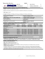
Material Safety Data SheetsW. F. Wells Incorporated supplies the following Material Safety Data Sheets,furnished us by the original manufacturer of the product, as a material used in ourequipment of manufacture.Responsibility for accuracy of information therein rests with the manufacturer ofthe product.It is our intent to seek out, use and pass along to our customers the safestproducts available, necessary to the operation of our equipment.1 st Ayd Gel Lube The product is rust-inhibitive fluid, used on all of our band sawmachine tools.The product is applied to unpainted surfaces before shipping the equipment.602623 MOBIL DTE 24 The product is hydraulic fluid, used in all of our band sawmachine tools.The product is in hydraulic fluid reservoirs, motors and cylinders activated withhydraulic fluid.Mobil SHC 634 Synthetic The product is gear case lubricant, used in our band sawmachine tools which utilize a gear reducer. The product is in the saw blade drive andpowered roll table drive gear reducer cases.21
NotesW. F. Wells, Inc.16645 Heimbach RoadThree Rivers, MI 49093-9684Phone 269.279.5123 Fax 269.279.6337Web Page: www.wfwells.com E-Mail: sales@wfwells.com22