MAX 9000 Programmable Logic Device Family Data Sheet
MAX 9000 Programmable Logic Device Family Data Sheet
MAX 9000 Programmable Logic Device Family Data Sheet

You also want an ePaper? Increase the reach of your titles
YUMPU automatically turns print PDFs into web optimized ePapers that Google loves.
<strong>MAX</strong> <strong>9000</strong> <strong>Programmable</strong> <strong>Logic</strong> <strong>Device</strong> <strong>Family</strong> <strong>Data</strong> <strong>Sheet</strong><br />
<strong>Programmable</strong><br />
Speed/Power<br />
Control<br />
<strong>MAX</strong> <strong>9000</strong> devices offer a power-saving mode that supports low-power<br />
operation across user-defined signal paths or the entire device. Because<br />
most logic applications require only a small fraction of all gates to operate<br />
at maximum frequency, this feature allows total power dissipation to be<br />
reduced by 50% or more.<br />
The designer can program each individual macrocell in a <strong>MAX</strong> <strong>9000</strong><br />
device for either high-speed (i.e., with the Turbo Bit option turned on) or<br />
low-power (i.e., with the Turbo Bit option turned off) operation. As a<br />
result, speed-critical paths in the design can run at high speed, while<br />
remaining paths operate at reduced power. Macrocells that run at low<br />
power incur a nominal timing delay adder (t LPA ) for the LAB local array<br />
delay (t LOCAL ).<br />
Design Security All <strong>MAX</strong> <strong>9000</strong> EPLDs contain a programmable security bit that controls<br />
access to the data programmed into the device. When this bit is<br />
programmed, a proprietary design implemented in the device cannot be<br />
copied or retrieved. This feature provides a high level of design security,<br />
because programmed data within EEPROM cells is invisible. The security<br />
bit that controls this function, as well as all other programmed data, is<br />
reset only when the device is erased.<br />
Generic Testing <strong>MAX</strong> <strong>9000</strong> EPLDs are fully functionally tested. Complete testing of each<br />
programmable EEPROM bit and all logic functionality ensures 100%<br />
programming yield. AC test measurements are taken under conditions<br />
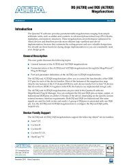
equivalent to those shown in Figure 12. Test patterns can be used and then<br />
erased during the early stages of the production flow.<br />
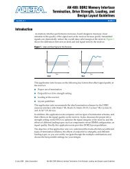
Figure 12. <strong>MAX</strong> <strong>9000</strong> AC Test Conditions<br />
Power supply transients can affect AC<br />
measurements. Simultaneous transitions of<br />
multiple outputs should be avoided for<br />
accurate measurement. Threshold tests<br />
must not be performed under AC<br />
conditions. Large-amplitude, fast groundcurrent<br />
transients normally occur as the<br />
device outputs discharge the load<br />
capacitances. When these transients flow<br />
through the parasitic inductance between<br />
the device ground pin and the test system<br />
ground, significant reductions in<br />
observable noise immunity can result.<br />
Numbers in parentheses are for 3.3-V<br />
outputs. Numbers without parentheses are<br />
for 5.0-V devices or outputs.<br />
464 Ω<br />
(703 Ω)<br />
<strong>Device</strong><br />
Output<br />
250 Ω<br />
(8.06 KΩ)<br />
<strong>Device</strong> input<br />
rise and fall<br />
times < 3 ns<br />
26 Altera Corporation<br />
VCC<br />
To Test<br />
System<br />
C1 (includes<br />
JIG capacitance)