2.5 DREDGE ASSEMBLY INSTRUCTIONS - Keene Engineering
2.5 DREDGE ASSEMBLY INSTRUCTIONS - Keene Engineering
2.5 DREDGE ASSEMBLY INSTRUCTIONS - Keene Engineering

You also want an ePaper? Increase the reach of your titles
YUMPU automatically turns print PDFs into web optimized ePapers that Google loves.
<strong>2.5</strong> " <strong>DREDGE</strong> <strong>ASSEMBLY</strong> <strong>INSTRUCTIONS</strong><br />
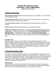
TOP VIEW OF <strong>2.5</strong>" <strong>DREDGE</strong> FRAME<br />
The dredge frame comes in 5 main pieces.<br />
1. 1 Engine mounting section.<br />
2. 1 Sluice mounting section.<br />
3. 1 Sluice box tracking bar.<br />
4. 2 Side support handles.<br />
Jet support hanger<br />
is supported by a<br />
bolt and crown nut.<br />
Push pins.<br />
Retractable jet<br />
support bars can<br />
be retracted for<br />
transporting or<br />
storage<br />
Frame slides together at the center joint and<br />
the floats keep the frame from seperating.<br />
Sluice tracking bar slides back and forth on the<br />
dredge frame, providing more or less tilt on the<br />
sluice. Once sluice is in proper position, tighten<br />
down the large wing bolts.<br />
Frame and floats are<br />
held together with<br />
frame locking pins.<br />
Side support frame handles<br />
Tracking bar studs with locking pins<br />
Sluice box tracking bar slides forward and backwards<br />
to adjust the sluice box angle.
<strong>2.5</strong> " <strong>DREDGE</strong> <strong>ASSEMBLY</strong> <strong>INSTRUCTIONS</strong><br />
Top view<br />
The power jet or suction<br />
hose is supported by the<br />
jet support hanger.<br />
Power Jet or hose connector<br />
slides into jet flare approximalty<br />
three inches and is held in place<br />
by the T handle hose clamp.<br />
Jet flare<br />
Engine can be mounted<br />
with or with out base<br />
plate for this frame.
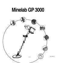
<strong>2.5</strong>" Dredge Side View<br />
1 1/4" to 1 1/2" adaptor<br />
Power Jet Model<br />
Engine portion of the frame is higher<br />
Power Jet uses short<br />
4' pressure hose<br />
Sluice portion of<br />
frame is lower<br />
<strong>2.5</strong>" power jet<br />
<strong>2.5</strong>" suction tip<br />
1 1/4" to 1 1/2" adaptor<br />
Suction Nozzle Model<br />
<strong>2.5</strong>" suction nozzle uses long<br />
17' pressure hose.<br />
<strong>2.5</strong>" hose connector
Inside view of <strong>2.5</strong>" sluice<br />
<strong>2.5</strong>" jet flare<br />
Rubber ribbed matting plate slides<br />
under the jet flare support bracket<br />
and is held down with the classifier<br />
screen and wing bolt.<br />
Removable aluminum lip helps seal and secure<br />
the Jet flare to the box.Aluminum lip is removed<br />
when high banker hopperis placed into sluice box.<br />
Large 1 1/2"<br />
fender washers<br />
Crown<br />
Nut<br />
Black rubber ribbed<br />
matting plate slides<br />
under the removable<br />
aluminum jet flare<br />
support bracket.<br />
Wingnut and washer holds<br />
the classifier screen down<br />
against the rubber ribbed<br />
matting plate.<br />
Wing nuts located on<br />
outside of sluice.<br />
<strong>2.5</strong>" jet flare<br />
Riffle<br />
side rail<br />
Classifier screen<br />
locking Pin<br />
Blue ribbed carpet<br />
Blue ribbed carpet<br />
Two large holes are located in the sluice box bottom support aluminim brace.<br />
The brace slides over the sluice tracking bar and is secured by locking pins.<br />
Side view of sluice<br />
box tracking bar.
2503 Conversion Assembly<br />
Instructions<br />
End of Sluice Box<br />
Slides<br />
Under Metal Tabs.<br />
Small aluminum<br />
adaptor plate bolts<br />
onto the outside<br />
of the sluice box.<br />
Hinge<br />
Spray bars<br />
end<br />
cap<br />
Classifier screen<br />
Classifier screen is held in<br />
place by a wing nut & washer<br />
Adjustment holes<br />
Angle of<br />
Adjustment<br />
Standard ribbed carpet<br />
Miners Moss and<br />
wire screen<br />
Rubber Ribbed matting<br />
on aluminum is held down<br />
by the classifier screen
Connects to pressure hose from water pump.<br />
Connects to garden hose<br />
for washing out the sluice<br />
box and cracks or crevices<br />
in bedrock. Replace cap<br />
when not in use to seal port.<br />
Ball valve for controlling<br />
water flow to the spray bar.<br />
and water pressure to the<br />
garden hose port.<br />
The spray bars can be adjusted to angle of flow of water to<br />
compensate for higher or lower pump pressure.<br />
The PVC spray bars and end caps are not glued together so they<br />
can be disasembled for cleaning or rotated for various types of<br />
material. A pair of channel locks may be required for removal of<br />
the end caps and spraybar adjustment.<br />
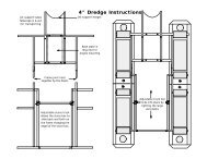
INSTALLATION OF SLUICE BOX TO HOPPER<br />
Remove classifer screen and drill 3 each 1/4 inch holes in the<br />
bottom of the sluice hopper and sluice box (A51) or trough<br />
extension which is used to extend the A52 sluice box.<br />
Bolt the sluice box to the hopper with the provided 1/4 inch<br />
nut, bolt and washers. An applcation of a light bead of silicone<br />
sealer along the edges will provide a better seal.<br />
Hinge<br />
Spray bars<br />
end<br />
cap<br />
Angle of<br />
Adjustment<br />
Adjustment holes<br />
Classifier screen is adjustable<br />
up and down depending on the<br />
type of material.<br />
The classifier screen should be adjusted to the upper position for hard pack material or<br />
heavy clay. The classifier screen should be moved as low as possible to maximize<br />
production, however you should check the tailings to see if the oversized gravel is free<br />
of any small or loose material.
HBCKF Assembly Instructions<br />
End of Sluice Box<br />
Slides<br />
Under Metal Tabs.<br />
Small aluminum<br />
adaptor plate bolts<br />
onto the outside<br />
of the sluice box.<br />
The legs slide up and down to accomodate<br />
different types of terrain. The leg is secured<br />
into place by tightening the large wing bolts.<br />
Adjust angle of sliding support bar to regulate the flow of water for proper riffle action.<br />
Do not allow black sands to overflow the riffles.<br />
Shown with A51 Mini Sluice<br />
Riffle side rails<br />
Adaptor plate<br />
A51 A52 SB2F<br />
Use a nut and bolt through the lower hole in the adaptor plate to secure the leg<br />
frame assembly to the sluice box.Note: When using the A52 Sluice, you may want<br />
to replace the flair with the trough extension for a better fit.
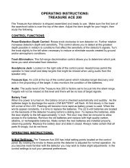
GENERAL OPERATING <strong>INSTRUCTIONS</strong><br />
THE FOLLOWING INFORMATION SHOULD ENABLE YOU TO UNDERSTAND THE<br />
BASIC THEORY OF OPERATION OF A PORTABLE <strong>DREDGE</strong>.<br />
For more complete understanding on this subject, we recommend you read any one of a variety of books available<br />
through the <strong>Keene</strong> Library of Books, such as The Gold Miners Handbook, Dredging for Gold or Advanced Dredging<br />
Techniques. The vacuum on a portable dredge is created by a "venturi principal". A volume of water is pumped through<br />
a tapered orifice (jet), by a special designed water pump. A high velocity jet stream is created within the jet tube producing<br />
a powerful vacuum. As indicated in the diagram gravel is dredged into the suction hose and is delivered to the sluice<br />
jet flare. As a slurry of water and gravel enters the jet flare and is spread evenly over a classifier screen. The smaller and<br />
heavier particles drop below the classifier screen into an area of less velocity, allowing a slower and more selective classification<br />
of values. Often values are recovered and easily observed before they even enter the riffle section. The lighter<br />
non bearing values and larger aggregate are returned back into the water. The riffles, or gold traps in the sluice box are<br />
best described as "Hungarian Riffles". This type of riffle has proven to be the most efficient gold recovery system. As<br />
material flows over the riffles, a vortex, or eddy current is formed between each riffle opening. This force allows the heavier<br />
material to settle out of suspension and the lighter, non value bearing material to be washed away. This continuous<br />
self cleaning principal allows a dredge to be operated for prolonged periods of time. Normal conditions require a sluice<br />
box to be cleaned only once or twice a day.<br />
PRIMING THE PUMP<br />
Before starting the engine, the pump must be fully primed. This means the pump must be full of water and all air<br />
removed. All jetting pumps provided with our dredges have a mechanical water pump seal. Without the presence of<br />
water in the pump, friction could cause a seal to overheat and require replacement. Priming the pump on some of the<br />
smaller models is accomplished by thrusting the foot valve back and forth under the surface of the water in a reciprocating<br />
motion. This will pump water into the foot valve assembly and into the pump. A pump is fully primed when water is<br />
observed flowing out of the discharge end of the pump. It may sometimes become necessary to hold the discharge<br />
hose above the level of the pump to complete the priming operation. The larger dredges that have a rigid foot valve, are<br />
easily primed by removing the cap provided on the foot valve and filling, until water overflows. Caution must be exercised<br />
to prevent sand from entering the foot valve or intake portion of the pump. Excess amounts of sand could damage the<br />
water pump seal, or pump impeller. It is recommended that the intake portion of the foot valve be placed in a sand free<br />
environment underwater, such as a small bucket or pan.<br />
PRIMING THE SUCTION HOSE<br />
Priming the suction hose need not be of concern in most dredging operations, but is important to understand the principal.<br />
When the tip of the suction hose is taken out of the water during operation air will enter the suction system and<br />
cause the suction power to cease temporarily, until submerged again. The suction will commence as soon as the air has<br />
passed through the system. It is important to ensure that no air leaks occur in the suction system.<br />
SUCTION SYSTEM OBSTRUCTIONS<br />
The suction system can become jammed while dredging. This can be caused by dredging an excess of sand, causing<br />
the suction hose to load up, or a rock that has become stuck in the suction system. Rock jams generally occur in the jet,<br />
or just before entry into the jet. This can easily be cleared by removed by flipping the rubber damper back over the jet<br />
flare and thrusting the probe rod down through the jet flare and jet in an effort to strike the obstructed area. It may occasionally<br />
be necessary to remove the suction hose to remove an obstruction. If this is not successful. it may be necessary<br />
to locate the blockage in the transparent hose and dislodge it by a striking the obstruction, taking care not to damage the<br />
hose.<br />
SOLID CONTENT<br />
Care must be exercised to prevent dredging excess amounts of sand. A solid to water balance must be maintained. The<br />
solid content being dredged should never exceed 10%. If a suction tip is buried in the sand and not metered properly the<br />
solid content could cause the suction hose to become overloaded with solids and suction will cease, this will also cause<br />
the sluice box to become overloaded with solid content, resulting in a loss of values.<br />
SLUICE BOX ADJUSTMENT<br />
Most models have a slight adjustment to raise or lower the sluice box. The proper sluice box adjustment can effect the<br />
recovery of values. If the sluice does not have enough angle, the sluice box will "load up" causing the riffle openings to<br />
fill with unwanted excess material. Too much angle will cause the material to flow too fast, resulting in loss of values, evidenced<br />
by the riffles running too clean. The optimum adjustment of a properly working sluice box is evident by only a<br />
portion of the riffle is visible while operating. A loss of values can also occur if the solid content of the suction discharge is<br />
too heavy in solid content. Remember, the solid content should not exceed 10 %. A normal sluice box tilt is approximately<br />
3/4” inch to the running foot. Afour foot sluice box should have an approximate tilt of 3"<br />
CLEANING THE SLUICE BOX<br />
Before attempting to clean the sluice box, it should be allowed to run with only water for a few minutes in order to wash
out any excess gravels that have accumulated. Either turn engine off, or let run with a slow idle, then remove the classifier<br />
screen and replace the wing nut to prevent losing it. Unsnap the riffle latches, fold the riffle tray up, and let rest against<br />
the jet flare, taking care not to let it drop back into place while cleaning. This could result in a potential injury! Place a<br />
wide tray, bucket or large gold pan at the end of the sluice, then carefully roll up the riffle matting and wash into the container<br />
at the end of the sluice. Rinse any excess gravel that remains in the sluice into container. All material must be<br />
removed before replacing the riffle matting, riffle tray and classifier screen.<br />
ENGINE SPEED<br />
Most small engines are throttle controlled. The speed of the engine can be controlled with the use of a lever. Although<br />
the rated horsepower is achieved on most small engines at 3600 R.P.M., it may not be necessary to operate the dredge<br />
at full speed. Lower speeds conserve engine life and fuel economy. Be sure to read all instructions and especially the<br />
engine instructions that are provided with each unit. ENGINES ARE NOT SHIPPED FROM THE FACTORY CONTAIN-<br />
ING OIL. OIL MUST ADDED PRIOR TO USE! ENGINES OPERATED WITHOUT SUFFICIENT OIL S U P P LY W I L L<br />
INVALIDATE ENGINE WARRANTEE!<br />
TROUBLE SHOOTING<br />
[A] IF SUCTION DECLINES<br />
1. Check the suction device for an obstruction. An obstruction can be removed by probing the obstructed area with the<br />
provided probe rod. I may be necessary to check the suction hose for a visible obstruction. This can be remedied by<br />
either back flushing the system or dislodging the obstruction with a gentle blow.<br />
2. Check the pump for loss of prime or blockage. The foot valve may be too close to the surface of the water and air may<br />
enter the intake of the pump via a small whirlpool. The pump intake or foot valve screen may be plugged with leaves or<br />
moss, restricting flow into the intake of the pump. Check and tighten all clamps to prevent an air leak.<br />
[B] IF PRIMING THE PUMP BECOMES DIFFICULT<br />
1. Check all clamps for an air leak.<br />
2. It may be necessary to check the foot valve for a small leak. This is accomplished by removing the foot valve assembly<br />
from the pump and blowing air into the hose portion of the assembly and listening for an air escape. It may be necessary<br />
to remove the hose and check the rubber valve for an evidence of a leak, or for a small obstruction preventing the<br />
valve from sealing.<br />
3. If a water pump seal is either defective or damaged, a leak will be evident on the inside portion of the pump around<br />
the drive shaft. Often a new pump will leak slightly, until the seal and gasket has become fully seated. This is a common<br />
occurrence in most new pumps.<br />
INTAKE HOSE<br />
PUMP<br />
SUCTION<br />
NOZZLE<br />
FOOT VALVE<br />
PRESSURE<br />
HOSE<br />
RIFFLES<br />
SLUICE BOX<br />
POWER JET<br />
SUCTION HOSE
11<br />
12<br />
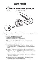
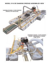
CENTRIFUGAL PUMP <strong>ASSEMBLY</strong><br />
STANDARD 5/8" TREADED SHAFT ENGINE<br />
10<br />
THREADED<br />
ENGINE<br />
SHAFT<br />
1 2 3 4 5 6 7 8 9<br />
P100 and P180 PUMPS<br />
INSTALLATION NOTES:<br />
The rotation of all is counter-clockwise. Water must be contained within the pump while it is running. Do not run the<br />
pump dry, as it will damage the pump seal and may lead to the need to replace the seal. To ensure continuous<br />
performance, it is always a good idea to carry a spare seal, in case you need to replace it. For maximum pump<br />
performance, use only <strong>Keene</strong> <strong>Engineering</strong> foot valves.<br />
INSTALLATION <strong>INSTRUCTIONS</strong>:<br />
1. Before installing the mounting plate (7) to the engine, the spring portion of the water pump seal (5) must be installed.<br />
Place this portion of the seal into the center of the mounting plate, with the use of a light hammer and or blunt<br />
instrument and a seal setting tool. Tap the perimeter metal portion of the seal to set the seal into position. Care must be<br />
taken to avoid contact with the carbon portion of the seal. A small amount of Silicone Rubber Cement placed in this<br />
section will insure a water tight seal. Insert the FOURmounting bolts (6) into the mounting plate (7). Tighten the bolts<br />
evenly so as to prevent mis-alignment.<br />
2. Fit "O" Ring gasket (OR1) into "O" slot on the front face of the mounting plate, making sure that it is properly<br />
seated. Place the ceramic portion of the water pump seal (4) into the center of the impeller (3) firmly, using the heal of<br />
your hand to insure a proper fit. The ceramic surface of the seal must be facing outwards. Thread the impeller onto the<br />
engine shaft by turning it gently in a clockwise rotation, taking care to avoid damage to the threads on the impeller.<br />
3. Attach the outer housing (2) to the mounting plate, using the housing bolts (8) and washers (8A). Tighten the<br />
housing bolts evenly to ensure proper tension and alignment. Extreme care must be taken to prevent over tightening of<br />
the bolts. Too much torque will damage the threads in the outer housing.<br />
P100<br />
P180<br />
ITEM DESCRIPTION QUANTITY PART NO. PART NO.<br />
1 HOSE ADAPTER 1 HA1 HA1<br />
2 OUTER HOUSING 1 101 181<br />
3 IMPELLAR 1 102 182<br />
4 PUMP SEAL (CERAMIC SEAL) 1 WPS2(PT.1) WPS2(PT.1)<br />
5 PUMP SEAL (SPRING & CASING) 1 WPS2(PT.2) WPS2(PT.2)<br />
6 MOUNTING PLATE BOLT 3 MB MB<br />
7 MOUNTING(BACK) PLATE 1 105 105<br />
8 HOUSING BOLT 4 HB HB<br />
8A HOUSING BOLT WASHERS 4 HW HW<br />
9 SHAFT BUSHING 1 SB SB<br />
9A COMPRESSOR DRIVE 1 P3 P3<br />
10 "O" RING(GASKET) 1 104 104<br />
11 FLUSHER ADAPTER CAP 1 FAC FAC<br />
12 FLUSHER ADAPTER 1 FA FA<br />
13 FAC RUBBER SEAL(INSIDE CAP) 1 FACS FACS
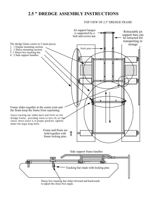
P90 Pump Breakdown Assembly<br />
1 8<br />
3<br />
2<br />
4<br />
5<br />
6<br />
7<br />
Component Quantity Part Description<br />
Number Used Number<br />
1 1 903 P90 PUMP MOUNTING PLATE<br />
2 1 951 P90 PUMP HOUSING<br />
3 1 952 P90 PUMP IMPELLER<br />
4 1 WPS2 PUMP SEAL <strong>2.5</strong>/3.5/5HP<br />
5 1 953 P-90 CORK GASKET<br />
6 4 AHSFH250281000 Flat Head allen head bolt 1/4"-28x1"<br />
7 4 AHS250201250 1/4"-20 X 1 1/4" ALLEN HEAD BOLT<br />
8 1 954 1/4 28 x 1 Full Thread Stud<br />
9 1 P90H (Not Shown) New Handle for P90GH <strong>2.5</strong> Honda<br />
SEAL REMOVAL AND INSTALLATION<br />
1. Remove the four housing bolts and remove the pump housing. 2 The impeller is directly<br />
mounted to the engine shaft. Unscrew in a counter clockwise direction. Lock the shaft in a fixed<br />
position to prevent it from turning. Insert a simple a pointed tool such as a screwdriver or an awl<br />
through starter housing cover, locking the flywheel into place. Rotate the pump impeller counterclockwise<br />
until it breaks loose. Unscrew the impeller until it comes off. All of our pumps use<br />
a two piece seal assembly. The ceramic side of the seal fits in side the back of the (3) P90 PUMP<br />
IMPELER. . The rubber side goes against the impeller. The spring loaded side is pressed inside<br />
the (1) P90 PUMP MOUNTING PLATE. The spring side of the seal should be pressed in with a<br />
thin bead of silicon sealant. We recommend that the seal be pressed in with or pump setting tool<br />
WPK2 Pump Seal Kit. Thread the impeller onto the engine shaft until the impeller is hand tight.<br />
Install the housing and use care not to over tighten the bolts to avoid stripping the threads as<br />
they are a soft alloy aluminum.<br />
ALWAYS REMEMBER THAT RUNNING YOUR PUMP DRY WILL LEAD TO POSSIBLE DAM-<br />
AGE AND DESTRUCTION OF THE WATER PUMP SEALS. IT IS RECOMMENDED TO KEEP<br />
A SPARE WATER PUMP SEAL KIT (WPK2) AND ONE ADDITIONAL WATER PUMP SEAL<br />
(WPK2) WHEN WORKING IN AN ISOLATED AREA.<br />
See “INSTALLATION & REPLACEMENT OF A PUMP SEAL, HOSE COUPLER &<br />
COMPRESSOR DRIVE <strong>ASSEMBLY</strong>” For further details on pump repair.
KEENE ENGINEERING<br />
20201 Bahama Street Chatsworth California 91311<br />
Tel. (818)-993-0411 Fax. (818)-993-0447<br />
E-mail: keene@jetlink.net<br />
Web site www.keeneengineering.com<br />
INSTALLATION & REPLACEMENT OF A PUMP SEAL, MARLEX PUMP<br />
COUPLER & A COMPRESSOR DRIVE <strong>ASSEMBLY</strong><br />
The water pump seal must be replaced if water is observed leaking between the engine and pump<br />
adapter or around the engine shaft,. To replace a seal or to install a compressor drive assembly (engine<br />
shaft pulley and drive belt), the pump must first be removed from the engine.<br />
<strong>INSTRUCTIONS</strong> TO REMOVE THE PUMP FROM THE ENGINE:<br />
Note: If the pump has been in use for a year or more, we suggest that you apply a penetrant such as<br />
"WD-40" to the engine shaft threads and allow it to penetrate the threads of the engine shaft. Saturate for<br />
24 hours before attempting to remove the impeller from the engine shaft!<br />
1. Remove the four housing bolts and remove the pump housing. If the housing does not pull off easily,<br />
gently pry it off with a screwdriver. Inspect the housing gasket and replace if necessary.<br />
2. The impeller is directly mounted to the engine shaft and will unscrew in a counter clockwise direction.<br />
Before attempting to remove the impeller the engine shaft must be locked in a fixed position to prevent<br />
it from turning. A simple way of locking the shaft is to insert a pointed tool such as a screwdriver or an awl<br />
through one of the many holes in the starter assembly and turning the engine over until the tool is firmly<br />
locked in place by the starter housing cover.<br />
IMPORTANT: Always disconnect the spark plug wire before attempting any repairs or service on your<br />
pump or engine. Once the engine shaft is locked into position, there are two methods that can be used<br />
to remove the impeller.<br />
Method #1. Use a block of wood, such as a 2x4 and place one corner of it into one of the impeller vanes<br />
on the left side of the impeller and strike the block of wood sharply with a hammer. This should loosen<br />
the impeller and enable it to be unscrewed in a counter clock-wise direction.<br />
Method #2. If the above is not successful, use a thin breaker bar or a heavy duty screw driver. Insert the<br />
blade into one of the impeller vanes towards the left side and try to unscrew the impeller by applying a<br />
downward pressure. If this still does not work carefully strike the end of the bar with a hammer until the<br />
impeller loosens from the shaft. If this still does not work, strike gently with a hammer. This method may<br />
cause a chip in the vane of the impeller. Depending on the size break of the corner of the impeller, it may<br />
or may not have adverse effects on the performance of the pump. So be careful!<br />
SEAL REMOVAL AND INSTALLATION:<br />
1. All of our pumps use a two piece seal assembly, with the exception of some older models (P-50<br />
and P-60). One half of the seal located in the backside of the impeller is called the "seat", or ceramic<br />
portion. The other side of the seal is shrouded in a brass encasement, encasing a hardened material that<br />
rests against the ceramic portion of the seal. Always replace both sides of the seal. Remove the ceramic<br />
portion with a sharp object similar to a screwdriver and press the new seat into place by hand. Always<br />
inspect the seal to note that it is not cracked. Always place the smooth surface of the seal to the outside.
2. Remove the pump adapter from the engine and press the brass portion of the seal towards the<br />
outside from the back of the adapter. If it cannot be pressed out easily, place a screwdriver handle on<br />
the seal and gently tap it out. When replacing, it is suggested that a small amount of silicone sealant be<br />
placed on the brass portion that fits into the adapter to ensure that it will not leak. Be careful not to get any<br />
sealant on the face of the seal. Position the seal in the center of the hole and press gently by hand into<br />
the cavity as far as possible. Use a screwdriver or a blunt instrument and tap the seal gently around the<br />
edge of the seal in a circular motion until the seal is firmly fitted into place. Wipe off seal facing with a clean<br />
cloth before reassembling.<br />
3. After both sides of the seals is installed, replace the pump adapter onto the engine and carefully<br />
tighten. Thread the impeller onto the engine shaft until the impeller is hand tight. Install the housing and<br />
use care not to over tighten the bolts to avoid stripping the threads as they are a soft alloy aluminum.<br />
HOW TO INSTALL THE HOSE ADAPTOR PUMP INTAKE COUPLER: (For all models except the<br />
P-50 and P-300 Series).<br />
The tolerance of the Hose Adapter is critical for proper pump performance. The hose Adapter should<br />
be installed as close as possible to the intake portion of the impeller. Center the adapter into the housing<br />
opening and press in by hand to locate it into place and place a wooden block against the outside of the<br />
adapter and gently tap until the adapter is firmly seated against the face of the impeller. Pull the starter<br />
rope until the engine turns. When the coupler is properly seated, the engine should be somewhat<br />
difficult to turn over, making sure that the adapter is against the face of the impeller.<br />
COMPRESSOR DRIVE INSTALLATION:<br />
To install the shaft pulley and belt for a compressor adaptation, the pump must be completely removed<br />
from the engine. For larger engines to include the 8 HP through 18 HP engines, slide the pulley to the<br />
back of the engine shaft and tighten the set screw. To install the engine pulley on smaller engines to<br />
include the 3HP to 5HP Engines, the furnished bushing should be pressed onto the pulley at the factory<br />
to ensure proper alignment and spacing. If you choose to install it yourself, this can be accomplished by<br />
placing the pulley on a flat surface, center the bushing in the hole of the pulley and gently drive it through<br />
by tapping it with a hammer taking care not to damage the bushing. The bushing should be pressed or<br />
driven through the pulley, in a flush position to the other side of the pulley. It should not extend though<br />
the other side. Then install the V Belt before placing the pulley and bushing over the engine shaft. After<br />
the pump is installed and secured, mount the compressor and compressor pulley. Install the V Belt to<br />
compressor and make sure that the alignment is correct. You can compensate for some misalignment by<br />
adjusting the compressor pulley on the compressor shaft. Tighten firmly the set screw and all bolt and<br />
check for any misalignment before starting.