8040 Dredge Instructions - Keene Engineering
8040 Dredge Instructions - Keene Engineering
8040 Dredge Instructions - Keene Engineering

Create successful ePaper yourself
Turn your PDF publications into a flip-book with our unique Google optimized e-Paper software.
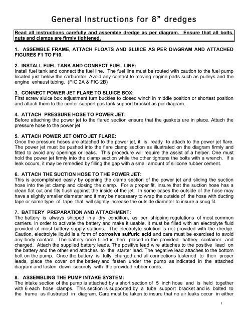
General <strong>Instructions</strong> for 8” dredges<br />
Read all instructions carefully and assemble dredge as per diagram. Ensure that all bolts,<br />
nuts and clamps are firmly tightened.<br />
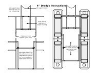
1. ASSEMBLE FRAME, ATTACH FLOATS AND SLUICE AS PER DIAGRAM AND ATTACHED<br />
FIGURES F1 TO F10.<br />
2. INSTALL FUEL TANK AND CONNECT FUEL LINE:<br />
Install fuel tank and connect the fuel line. The fuel line must be routed with caution to the fuel pump<br />
located just below the carburetor. Avoid any contact to moving engine parts such as pulleys and the<br />
engine exhaust tubing. (FIG 2A & FIG 2B)<br />
3. CONNECT POWER JET FLARE TO SLUICE BOX:<br />
First screw sluice box adjustment turn buckles to closed winch in middle position or shortest position<br />
and attach them to the center support gas tank support bracket as per diagram.<br />
4. ATTACH PRESSURE HOSE TO POWER JET:<br />
Before attaching the power jet to the flared section ensure that the gaskets are in place. Attach the<br />
pressure hose to the power jet<br />
5. ATTACH POWER JET ONTO JET FLARE:<br />
Once the pressure hoses are attached to the power jet, it is ready to attach to the power jet flare.<br />
The power jet must be pushed into the flare clamp section as illustrated on the diagram firmly and<br />
fitted to avoid any openings or leaks. This procedure will require the assist of a helper. One must<br />
hold the power jet firmly into the clamp section while the other tightens the bolts with a wrench. If a<br />
leak occurs, it may be remedied by filling the gap with a small amount of silicone rubber cement.<br />
6. ATTACH THE SUCTION HOSE TO THE POWER JET:<br />
This is accomplished easily by opening the clamp section of the power jet and sliding the suction<br />
hose into the jet clamp and closing the clamp. For a proper fit, insure that the suction hose has a<br />
clean flat cut and fits flush against the inside of the jet. In some cases the outside of the hose may<br />
have a slightly smaller diameter and it may be necessary to wrap the outside of the hose with ducting<br />
tape or some type of tape that will slightly increase the outside diameter to insure a snug fit.<br />
7. BATTERY PREPARATION AND ATTACHMENT:<br />
The battery is always shipped in a dry condition, as per shipping regulations of most common<br />
carriers. In order to activate the battery and make it usable, it must be filled with an electrolyte fluid<br />
provided at most battery supply stations. The electrolyte solution is not provided with the dredge.<br />
Caution, electrolyte liquid is a form of corrosive sulfuric acid and care must be exercised to avoid<br />
any body contact. The battery once filled is then placed in the provided battery container and<br />
charged. Attach the supplied battery leads. The positive lead wire attaches to the positive lead on<br />
the battery and the other end attaches to the starter lead. The negative lead attaches to the bottom<br />
bolt on the pump. Once the battery is fully charged and all connections fastened to their proper<br />
leads, place the cover on the battery and fasten under the pump as indicated in the attached<br />
diagram and fasten down securely with the provided rubber cords.<br />
8. ASSEMBLING THE PUMP INTAKE SYSTEM:<br />
The intake section of the pump is attached by a short section of 5 inch hose and is held together<br />
with 6 each hose clamps. This section is supported by a tube support bracket and is bolted to<br />
the frame as illustrated in diagram. Care must be taken to insure that no air leaks occur in either<br />
1
the intake or the discharge of the pump. An air leak in the intake system can prevent pump from<br />
priming. Priming simply means that all air is evacuated from the pump and intake system and is filled<br />
with water. If a leak exists when tightening a fitting or clamp, it is sometimes remedied by using<br />
silicone sealer or Teflon tape.<br />
9. BEFORE STARTING ENGINE:<br />
Always check engine oil level before starting. Check fuel filter for evidence of dirt or other particles<br />
blocking fuel flow. Before starting engine check to see that all items are clear from exposed pulleys,<br />
belts and any moving parts including your hands, hair or any part of your body. Make sure that the<br />
gas petcock valve on the gas tank is open. As closed valve will prevent fuel from flowing into the<br />
carburetor. Make a final check to see if there are no leaks and all valves are closed.<br />
10. PRIMING THE PUMP:<br />
To prime the pump the engine must be started and running at a low idle. Turn key to start. DO NOT<br />
RUN ENGINE FOR ANY PROLONGED PERIOD OF TIME WITHOUT PRIMING THE PUMP.<br />
Damage could result to the water pump seal. The water pump seal is a mechanical type and must<br />
have water to keep it lubricated and cool. Remove the cap located on the top of the foot valve and fill<br />
with water. Keep filling the foot valve until the water overflows. Replace the cap and tighten down.<br />
Your pump should now be primed. If all of your connections are tight, the pump should remain<br />
primed for several days.<br />
11. SLUICE BOX OPERATION (See diagram)<br />
The sluice box is designed with four different recovery sections. The first section is designed to<br />
recover all of the course gold and nuggets. This is a flared section of open riffles that widens into<br />
approximately 35 inches. The second section designed to recover medium to fine values, containing<br />
a set of shorter riffles with a perforated classifier screen that is elevated above the riffles to classify<br />
and carry the larger aggregate to the next stage of recovery. The third section of the upper riffles is<br />
the final recovery of medium to fine gold that may have escaped the previous sections of the sluice.<br />
The fourth and final recovery of the sluice is designed to recover any super fine gold that may have<br />
escaped the first previous recovery sections. All fine values that are minus 3/8ths of an inch in size<br />
are fed into a lower riffle section containing still smaller riffles and a section of expanded metal or<br />
screen for more precise selection of fine gold recovery. This section has an adjustable slide tray for<br />
regulating the amount of water and material that enters this section of riffles. For the proper opening<br />
adjustment, we recommend that you start with the slide tray open about 8" from the end of the<br />
sluice. If the lower section is not holding any material, the tray must be slid in slightly. This<br />
adjustment must be determined by the nature of the area being dredged. Adjustments will vary<br />
according to conditions of the gravel that exists in your area.<br />
12. FINAL CLEAN UP OF RECOVERED VALUES:<br />
The sluice system is self-cleaning and can be operated for extended periods of time. The average<br />
clean up of values is normally accomplished at the end of each day. This will vary depending on the<br />
types of gravel conditions and the size of the recovered values. In areas where heavy black sand<br />
exists, the sluice may have to be cleaned out more frequently. The sluice can be checked for the<br />
occurrence of values at any time without cleaning by simply by observing the first few riffles at the<br />
beginning of the sluice box. Experimentation in any new area is essential.<br />
13. SUCTION TIP (See diagram)<br />
The suction tip is equipped with a swivel for ease of operation and is recommended to occasionally<br />
lubricate with a light oil for insured O Ring life. The suction tip is also equipped with a suction<br />
breaking rubber flap that is necessary to break the suction when a large or irregular rock becomes<br />
stuck to the end of the tip. Without this suction breaking flap, it would be nearly impossible remove an<br />
obstruction.<br />
2
Rope Tie Downs<br />
FIG 1A Front main frame support with rope tie downs<br />
FIG 1B Center frame support<br />
FIG 1C Rear Sluice box and frame suport adjustable<br />
height for adjusting end of sluice.<br />
FIG 1D install ladder float frame at various locations.<br />
Can be positioned nearly anywhere on frame.<br />
FIG 1E install outrigger support assembly<br />
FIG 1F install outrigger side support assembly<br />
mount on opposite side of dredge.<br />
FIG 1G Assembly sluice box ladder to frane and<br />
bolts to fig.1C rear sluice box frame support.<br />
FIG 1H Assemble sluice box ladder to frame and<br />
bolt and bolt to rear frame support (Fig 1C).<br />
FIG 1I Connect winch and chains to support<br />
sluice box ladder.
Jet support chain connectors<br />
FIG 1K Install engine to mounting<br />
brackets on frame deck.<br />
FIG 1L install front decks and install jet support chains<br />
after engine is bolted securly into place.<br />
FIG 1J Winch and safety chain is used<br />
to raise and lower sluice box assembly.<br />
FIG 1O Connect pressure hose support to frame.<br />
FIG 1M Attach foot valve support brackets to<br />
engine frame.<br />
FIG 1N Shown is further detail of foot valve<br />
location and brackets.
FIG 2A Diesel Fuel line assembly<br />
FIG 2B Diesel fuel return line inserted into top of tank.<br />
FIG 2C Typical Air Snorkel attachmet to air<br />
compressors and air pressure hose assembly<br />
OPTIONAL CANOPY $895.00 Dimensions : 10’ (3.048m) x 10’ (3.048m) x 20’ (6.096m)<br />
Custom canopy mounting enables the use of a 10 foot wide x 20 foot long canopy providing sun<br />
and rain protection.Equipped with powder coated 1 3/8ths. steel frame with six removable legs<br />
Exhaust extension and necessary hardware to attach. A hole must be cut in canopy for to<br />
accommodate exhaust discharge.<br />
FIG 2D Air snorkel mounted on end of<br />
freame reduces chance of air contamination.
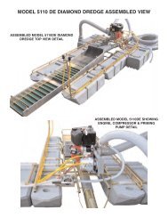
<strong>8040</strong> & 8080 Basic Frame<br />
Top View
<strong>8040</strong> & 8080 Basic Frame<br />
Side View<br />
Sluice ladder<br />
The Main dredge frame comes pre assembled<br />
with the floats attached to the frame sections<br />
Top View of sluice ladder.<br />
The sluice box mounts on<br />
top of the labber.
DETAIL<br />
NO.<br />
1S<br />
DETAIL<br />
NO.<br />
2S<br />
Water flow<br />
Riffle drops into the sluice<br />
Carpet is tucked under the riffle and up the sides<br />
2S<br />
2S<br />
2S<br />
2S<br />
<strong>8040</strong> MAIN SLUICE BOX - SIDE VIEW<br />
<strong>8040</strong> MAIN SLUICE BOX - PLAN VIEW
<strong>8040</strong> POWER JET PLUMBING<br />
FVA5<br />
(2) HDC4P<br />
(2) HDC4PT<br />
(2) HDC3P<br />
PI500<br />
PHC4F<br />
SP433<br />
PH4<br />
(2) HDC3P<br />
DIESEL ENGINE<br />
PH3<br />
(2) HDC3P<br />
3" VENTURI<br />
INJECTOR LOG<br />
(2) 263 COMPRESSORS<br />
PJ84 ( 8"X 3"X 3")<br />
3" VENTURI<br />
INJECTOR LOG<br />
SQC8<br />
(2) HDC3P
Introduction<br />
to Hookah Diving<br />
There are two air supply systems<br />
that are used for underwater diving<br />
activities. One system, known as Self<br />
Contained Underwater Breathing<br />
Apparatus (SCUBA), involves the use<br />
of high pressure metal tanks which<br />
are worn on the diver's back while<br />
diving. The equipment used in<br />
SCUBA diving is quite technical in<br />
nature, and SCUBA gear should not<br />
be used by persons who have not<br />
become a certified diver involving<br />
specialized instruction. Without a certification<br />
card indicating completion of<br />
such a course, you cannot purchase<br />
compressed air.<br />
Of course, the SCUBA air system<br />
has its advantages as well. A diver<br />
using SCUBAgear is literally "an entity<br />
unto himself," since he carries his<br />
life giving air supply on his back at all<br />
times. He can go anywhere he chooses,<br />
completely free of any ties with<br />
the world topside.<br />
There are many times when an<br />
underwater diver does not need the<br />
total freedom that is afforded by the<br />
S C U B A air system, particularly in<br />
cases in which the diver is submerged<br />
in a limited area for long periods<br />
of time.<br />
For these applications, the<br />
"Hookah" (Surface Air Supply) was<br />
invented. The The Hookah air system<br />
uses no high pressure air tanks<br />
of the type worn on a diver's back<br />
Instead, it uses a small air compressor<br />
which is located at the surface. It<br />
is commonly powered by a portable<br />
gasoline engine or electric motor, and<br />
the air is delivered to the diver via a<br />
floating air hose. With the Hookah<br />
system, the diver has an unlimited<br />
and nearly "cost free" air supply<br />
which will only stop flowing when the<br />
engine or motor that powers the compressor<br />
ceases to operate. T h i s<br />
makes for a truly economical air system,<br />
which will quickly pay for itself<br />
when compared to the cost of refilling<br />
a SCUBA tanks every hour or so.<br />
The only operating cost for a<br />
Hookah system is fuel, since the vast<br />
majority of Hookah compressor units<br />
are gasoline powered. It is not<br />
uncommon to get two hours diving<br />
time on a single gallon of gas, which<br />
shows just how economical the<br />
2<br />
Hookah air system can be.<br />
Most Hookah divers will have a<br />
partner working "topside" as a safety<br />
man, and he can refill the engine's<br />
gas tank as it starts getting low. This<br />
will enable the diver to stay submerged<br />
so long as he desires.<br />
THE AIR COMPRESSOR<br />
Typical Hookah Air Compressor<br />
Model T-80
The Hookah air system begins at<br />
the diver's air compressor. Hookah<br />
compressors are small, lightweight,<br />
and of simple design. They are commonly<br />
constructed of an aluminum<br />
alloy, and utilize a rubber diaphragm<br />
as the means of air displacement.<br />
There are also compressors that use<br />
a "piston" arrangement to displace air<br />
and these types generally deliver<br />
more air at higher pressures than the<br />
diaphragm models. The moving parts<br />
inside a Hookah compressor are<br />
lubricated with Teflon for the life of the<br />
unit, and need no additional lubrication;<br />
to do so may actually damage<br />
the compressor. The air that is delivered<br />
by this type of Hookah compressor<br />
is pure, oil free air. It is however<br />
recommended that at least a 40<br />
micron filter be included to remove<br />
any solid particles that may occur.<br />
This type of Hookah compressors<br />
contains sealed bearings rather than<br />
oil for lubrication which can contaminate<br />
the air supply. Most compressors<br />
utilize an “oil bath lubrication<br />
system which will contaminate the air<br />
supply.<br />
Hookah compressors operate at<br />
a relatively low pressure. The maximum<br />
pressure available from the<br />
higher capacity models is about 125<br />
pounds per square inch. The higher<br />
the operating pressure, the lower the<br />
air output. Consistently high operating<br />
pressures (unless the unit specifically<br />
designed for high pressure use)<br />
will shorten the life of the compressor<br />
by a noticeable degree. Conversely,<br />
the LOWER the operating pressure,<br />
the greater the air output, and the<br />
longer the compressor life. A compressor<br />
should not be operated at<br />
high pressures unless a diver intends<br />
to be submerged at greater depths. If<br />
a diver is working at depths of 33 feet<br />
or less, he will need only 30 to 40<br />
pounds per square inch for optimum<br />
operation of his regulator.<br />
Most Hookah compressors have<br />
a built in "pressure relief valve" which<br />
prevents excessive pressure from<br />
building up in the compressor head<br />
when the diver is only making a small<br />
"demand" on the compressor. This<br />
valve is usually preset at the factory<br />
at approximately 50 p.s.i., which will<br />
give the average diver at shallow<br />
depths enough air to operate his regulator<br />
while leaving enough pressure<br />
left over to allow for increased exertion.<br />
If a diver is breathing at a normal<br />
rate (light exertion), the pressure<br />
relief valve will occasionally "pop off"<br />
and shoot out a burst of air. This is<br />
normal, as it prevents excess buildup<br />
of pressure in the compressor head.<br />
If a diver is breathing heavily and is<br />
under physical exertion, he will be<br />
demanding all of the volume and<br />
pressure that the compressor can<br />
deliver. In this case, the pressure<br />
relief valve will rarely, if ever discharge<br />
excess pressure or "pop off."<br />
The type of Hookah compressor<br />
that is required for a given diving<br />
operation is dependent upon the<br />
extent of underwater physical exertion,<br />
the depth, and the number of<br />
divers that are connected to the system.<br />
A single diver under light exertion<br />
at shallow depths will require a<br />
relatively small air output that is measured<br />
in "cubic feet per minute," or<br />
"CFM". The same diver under heavy<br />
exertion will require additional air at a<br />
slightly higher pressure and volume.<br />
If more than one diver is connected<br />
to an air system, or if diving at<br />
greater than normal depths, more air<br />
volume at higher pressures may be<br />
required.<br />
Air Reserve Tank Model RT-1<br />
THE AIR RESERVE TANK<br />
The next major component in the<br />
Hookah air system is the reserve<br />
tank. This very important piece of<br />
equipment performs four vital functions:<br />
The reserve tank operates as an<br />
air ``reservoir," that supplies a constant<br />
volume of air at all times. If,<br />
you are diving under heavy exertion<br />
and demanding a greater amount of<br />
air, the large volume of air in the<br />
reserve tank will supply the reserve<br />
air required. If you were breathing<br />
directly from compressor itself, your<br />
rate of inhalation might actually surpass<br />
the air volume provided by the<br />
compressor, and you would not get a<br />
sufficient amount of air.<br />
3<br />
The reserve tank functions as a<br />
cooling and condensation vessel.<br />
Few divers realize it, but the air<br />
emerging from a Hookah compressor<br />
is quite hot, and can actually reach<br />
temperatures as high as 190<br />
degrees.<br />
As the air enters the the reserve<br />
tank, it will expand and cool. This<br />
expansion process will also condense<br />
most of the water contained in<br />
the compressed air. Hookah compressors,<br />
because of their small size,<br />
do not have the capability to remove<br />
the moisture from the air and hence,<br />
they deliver air with an appreciable<br />
moisture content. The expansion<br />
process in the reserve tank allows the<br />
water to condense, ensuring that the<br />
diver breaths less moisture in the air.<br />
The reserve tank also suppresses<br />
surges from the compressor or<br />
any temporary decrease in running<br />
speed. Often a the compressor's<br />
engine will run uneven due to moisture<br />
in the gasoline. The reserve<br />
tank can compensate for this by delivering<br />
an even flow of air.<br />
And finally, the most important<br />
function of all. The reserve tank will<br />
contain enough pressurized air to<br />
give the diver a couple of minutes<br />
breathing time, should his compressor,<br />
or engine failure run out of fuel.<br />
Equipment breakdown is not a pleasant<br />
thing to consider while working<br />
underwater, but is always a possibility.<br />
In the event of an engine failure<br />
without a reserve tank in the system,<br />
a diver could experience an immediate<br />
loss of air that could lead to desperation<br />
and panic. Any experienced<br />
diver will tell you, that panic is the<br />
leading cause of drowning incidents.<br />
THE AIR HOSE<br />
The next component in the<br />
Hookah air system is the air hose.<br />
Hookah air hose is made of a special<br />
vinyl plastic construction, is resistant<br />
to the effects of oil, gasoline and sunlight<br />
that exists in the environment.<br />
Conventional rubber hose should<br />
never be used for diving, because it<br />
will gradually deteriorate and become<br />
toxic. Hookah hose commonly has an<br />
inside diameter of 3/8ths. of an inch.<br />
It is constructed of an inner liner of<br />
food grade vinyl wrapped with a nylon<br />
webbing reinforcement and covered<br />
with a heavy duty PVC abrasion<br />
resistant wall. Hookah hose is
designed to prevent kinking and collapsing<br />
that could prevent the flow of<br />
air being shut off<br />
A quality Hookah hose will be colored<br />
a bright yellow or orange, for a<br />
high degree of visibility. It will also<br />
float, so that any excess hose not<br />
actually being used will float on the<br />
surface, completely away from the<br />
d i v e r, reducing the possibility of<br />
entanglements on the bottom. For<br />
example, if you are diving in ten feet<br />
of water but are using a thirty foot<br />
length of air hose, the excess twenty<br />
feet will float on the surface, completely<br />
away from you.<br />
A quality Hookah air will not<br />
impart any "flavoring" to the air, and<br />
should meet “F D A and OSHA”<br />
requirements.<br />
Typical Hookah Air Regulator<br />
and Harness<br />
THE REGULATOR<br />
The regulator is an oral respiration<br />
device that is worn in the divers<br />
mouth. The regulator regulates the<br />
amount of air that is received by the<br />
diver each time he inhales. Because<br />
the divers nose is covered by his face<br />
mask, air must be inhaled through the<br />
divers mouth .<br />
There are two types of diving regulators,<br />
those designed for SCUBA<br />
use and those designed for Hookah<br />
applications. A SCUBA regulator is<br />
designed for use with SCUBA a air<br />
tank, and delivers maximum efficiency<br />
when operated at a pressure<br />
exceeding 100 p.s.i. They require a<br />
"first stage" valve assembly, attached<br />
to the SCUBA tank. The function of<br />
the first stage is to reduce the<br />
extremely high pressure of the air in<br />
the SCUBA tank from approximately<br />
2,250 p.s.i. to approximately 180<br />
p.s.i. This pressure then goes to the<br />
Typical air system for one diver, including air hose, reserve tank,<br />
regulator, harness, and connector hose to compressor<br />
"second stage," which is the part that<br />
is worn in the diver's mouth. The second<br />
stage of a SCUBA regulator has<br />
a spring loaded "downstream" valve<br />
which delivers the correct amount of<br />
air to the diver when driven by an air<br />
pressure ranging from 100 to 250<br />
p.s.i.<br />
A prospective Hookah diver must<br />
realize that SCUBA regulators CAN-<br />
NOT be used for Hookah applications<br />
without special modifications. A typical<br />
Hookah compressor operates in<br />
an average pressure range of 30 to<br />
50 p.s.i., which is not enough pressure<br />
to drive the spring loaded downstream<br />
valve of a SCUBA regulator.<br />
A diver who already owns a SCUBA<br />
regulator, but who wishes to use it for<br />
Hookah applications, must take his<br />
regulator to a competent dive shop or<br />
repair station and get the regulator<br />
converted over for low pressure use;<br />
he should not attempt to do it himself.<br />
The conversion can be made by<br />
installing a set of low tension springs<br />
which will give maximum efficiency<br />
when operated at low Hookah pressures.<br />
A dive shop or repair station<br />
will also have the necessary test<br />
gauges, etc., to make certain the<br />
adaptation has been effective.<br />
A Hookah regulator is entirely different<br />
from a SCUBA regulator. It<br />
consists of a "second stage" only,<br />
which is fed directly from the output of<br />
the reserve tank via the air hose.<br />
There are no valve assemblies of the<br />
type that are used with SCUBA tanks.<br />
Hookah regulators employ a "tilt," or<br />
4<br />
"pin" valve, which delivers a full air<br />
flow to the diver at a pressure as low<br />
as 30 p.s.i. This type of regulator is<br />
specifically designed for use with low<br />
pressure Hookah compressors.<br />
Hookah regulators, as are all modern<br />
regulators, are of the single hose,<br />
"demand" type. A "demand" regulator<br />
works on a relatively low volume of<br />
air, since it only has to deliver air as<br />
the diver breathes, or "demands" it..<br />
THE HARNESS<br />
A regulator should not be used for<br />
Hookah diving unless it is in conjunction<br />
with a "chest harness." The harness<br />
serves two principle functions:<br />
1. It keeps the air hose from getting<br />
in the diver's way when he is working<br />
u n d e r w a t e r. The harness has a<br />
"back plate" which is automatically<br />
positioned over the center of the<br />
diver's back when the harness is<br />
Since the air hose terminates at the<br />
diver's back, it prevents potential<br />
entanglements around the diver's<br />
body.
2. The regulator intake hose that<br />
attaches to the check valve prevents<br />
any pulling motion from the regulator<br />
while working underwater. For example;<br />
if a diver were moving around<br />
underwater and inadvertently came<br />
to the end of the air hose, the harness<br />
would absorb the shock and the regulator<br />
and would not be jerked from<br />
the diver's mouth.<br />
INCIDENTAL ACCESSORIES,<br />
HOSES, HINTS, PRECAUTIONS:<br />
One accessory hose item you will<br />
need is a short length of hose for<br />
routing the air output from the compressor<br />
to the input of the reserve<br />
tank. The type of hose that is needed<br />
depends upon the compressor<br />
you are using. Diaphragm models<br />
that operate in the 30 to 50 p.s.i.<br />
range use a simple hose connector<br />
that is made of hookah air hose.<br />
The high pressure, high volume piston<br />
compressors that are capable of<br />
delivering pressure of 100 p.s.i.,<br />
require a connector made of special<br />
certified "heat resistant steam" hose,<br />
due to the fact that these models discharge<br />
air at higher temperatures.<br />
When setting up a Hookah air<br />
system, you will frequently need an<br />
array of metal fittings. For use<br />
around water, you should use stainless<br />
steel or brass fittings only. This<br />
is especially important when diving in<br />
salt water.<br />
Fittings made of ferrous metal will<br />
rust or corrode when used in, or near<br />
a water environment.<br />
If your Hookah compressor is<br />
powered by a gasoline engine, make<br />
every effort to ensure that the engine<br />
exhaust (which contains deadly carbon<br />
monoxide gas), is always placed<br />
DOWNWIND from the compressor.<br />
This will help prevent exhaust from<br />
being accidentally pulled into the<br />
compressor's air inlet. Always use a<br />
“snorkel” extension on any compressor<br />
that can elevate the intake of the<br />
air supply away from engine exhaust<br />
contaminates.<br />
Never use a gasoline powered<br />
compressor in confined areas, such<br />
as underneath piers, in close, narrow<br />
grottos, etc. This will prevent the<br />
exhaust gases from dissipating into<br />
the atmosphere safely. Also, never<br />
dive in an area where there is little<br />
ventilation or air movement. Take<br />
special precautions when diving in<br />
areas where the air is extremely still,<br />
as dead air spaces, or poor ventilation<br />
can cause exhaust gases to<br />
linger in the immediate area of the<br />
engine and compressor unit.<br />
Always install a long extension<br />
on the intake of your compressor to<br />
avoid the possibility of contamination<br />
of Carbon Monoxide Gas from the<br />
engine exhaust system. The air<br />
intake of a compressor must tower<br />
over the engine exhaust at a sufficient<br />
height or distance to avoid<br />
intake of engine exhaust gas. If this<br />
gas is inhaled even in small quantities<br />
for short periods, it can cause severe<br />
headaches and possibly result in<br />
sickness. In larger quantities it can<br />
kill you, so please be careful!<br />
If you are using Hookah equipment<br />
around salt water, be sure to<br />
rinse off all your components with<br />
freshwater afterwards. This includes<br />
your regulator, diving mask, harness,<br />
metal fittings, and air hose (flush it<br />
out on the inside as well as outside).<br />
A salt water environment will quickly<br />
corrode aluminum parts such as:<br />
Hookah compressors and gasoline<br />
engines. It is advisable to keep all<br />
metal components freshly painted<br />
and cleaned to avoid excess corrosion.<br />
If you are using a gasoline powered<br />
compressor always shut of the<br />
engine before attempting to refuel.<br />
Do not attempt to refill the engine's<br />
gas tank while the engine is still running,<br />
as this will increase the possibility<br />
of spilling gasoline onto a hot<br />
engine, which could result in a potential<br />
fire or cause an explosion.<br />
A diver should always surface<br />
and shut off the engine first prior to<br />
refueling and allow time for the<br />
engine to cool down. Always use a<br />
funnel for refilling the gas tank, or a<br />
special spillproof gas container to<br />
prevent spillage.<br />
Every Hookah diver should<br />
understand the basic rudiments of<br />
engine and compressor maintenance,<br />
and should always keep his<br />
equipment in top condition. If you<br />
take proper care of your equipment, it<br />
will give you many years of trouble<br />
free service. Knowing how to work on<br />
your own equipment will also come in<br />
handy, should you experience any<br />
mechanical failure on a diving trip. It<br />
is a good idea to carry<br />
5<br />
along some spare parts for your air<br />
compressor, and the necessary tools<br />
to make repairs.<br />
All of the basic "rules of the deep"<br />
that apply to SCUBAdiving also apply<br />
to Hookah diving as well.<br />
UNDER NO CIRCUMSTA N C E S<br />
SHOULD YOU DIVE ALONE.!<br />
Always Hookah dive with a partner<br />
who owns his own regulator, harness,<br />
and air hose.<br />
Make sure that his or her equipment<br />
as well as yours is attached to<br />
the air system at all times. If you<br />
were to experience underwater problems,<br />
your "diving partner" should be<br />
available to come to your immediate<br />
assistance.<br />
Even though no formal instruction<br />
is required to use Hookah<br />
equipment, we strongly recommend<br />
that all divers should take a<br />
“CERTIFIED SCUBA” course at<br />
your local county or diving supply<br />
store.<br />
You should also read books on<br />
the subject of underwater diving safety<br />
and study them thoroughly. This<br />
will further familiarize you with the<br />
"rules of the deep."<br />
New 12volt system HAS
WARNING CARBON MONOXIDE GAS<br />
If you're considering diving with a "Hookah Compressor" , It is most important that you become aware of<br />
Potential Danger associated with exhaust emissions. We place a caution label on the engine, warning of dangerous<br />
engine fumes and also illustrate further warning in " Introduction to Hookah Diving" and Safety in<br />
Gold Dredging that is issued with the purchase of all diving equipment.<br />
WHAT IS CARBON MONOXIDE GAS?<br />
Carbon Monoxide is an invisible odorless gas which gives no warning of its presence. It is the product of<br />
the incomplete burning of any material such as ; Oil Gasoline, Wood, Coal, etc. that contains carbon.<br />
WHAT IS THE EFFECT OF CARBON MONOXIDE EXPOSURE?<br />
Carbon Monoxide deprives the blood of its ability to carry oxygen throughout the body. When Carbon<br />
Monoxide is inhaled , it chemically combines with hemoglobin, the oxygen carrier in the blood. Even if<br />
there is plenty of oxygen in the air, hemoglobin combines much more readily with Carbon Monoxide than<br />
with oxygen. As the oxygen level of the blood is reduced, the heart must pump faster in an effort to supply<br />
sufficient amounts of oxygen to the brain and other parts of the body. When the brain does not receive<br />
enough oxygen, symptoms of headache, dizziness and mental confusion occur. Further exposure to the gas<br />
causes lack of coordination, weakness and nausea. The final effect of excessive exposure are convulsions,<br />
coma and death.<br />
Needless to say, we cannot emphasize strongly enough that caution must be exercised. Never dive alone,<br />
never dive in an enclosed area, or in an area where good ventilation is not eminent such as; under piers, narrow<br />
grottos, under heavily overgrown brush or trees or in any area where a good breeze does not occur.<br />
Always make an effort to position your air unit to allow the prevailing breeze to carry any exhaust emissions<br />
away from the air intake of the compressor.<br />
Remember, Carbon Monoxide is the product of incomplete burning of gasoline and oil, so it most important<br />
to keep your unit properly running and clean. Never allow gasoline to overfill or spill anywhere near engine<br />
and compressor.<br />
THE SAFETY AIR SNORKEL DOES NOT ELIMINATE CARBON MONOXIDE GAS, IT ONLY AIDS<br />
IN THE REDUCTION OF FUMES. ALL THE SAFETY CAUTIONS MUST BE OBSERVED !<br />
SNAP FIT<br />
REMOVE AIR FILTER FROM THE<br />
AIR COMPRESSOR AND INSTALL<br />
IN THE TOP OF THE AIR SNORKEL<br />
1/4-20 X 2"<br />
BOLT<br />
ALUMINUM SNORKELSUPPORTS<br />
#10-24 X 2.5"<br />
BOLT<br />
ALUMINUM<br />
SPACER<br />
SNORKEL SLIDES INSIDE<br />
THE COMPRESSOR INTAKE<br />
1/4" NYLON NUT<br />
AND WASHER<br />
#10 NUTS<br />
STABILIZING<br />
BRACKET<br />
#10-24 X 1/5<br />
PHILLIP PAN HEAD<br />
6
Optional Recommended<br />
Air filter (CDAF)<br />
A4<br />
THIS IS THE AIR SUPPLY<br />
COMING FROM THE H.P.<br />
COMPRESSOR<br />
HC1ST<br />
A2<br />
A5C<br />
1/4 F X 1/2M<br />
RT9S AND RT25S STAINLESS STEEL<br />
TANK<br />
A5C<br />
1/4 F X 1/2M<br />
A5C<br />
A5G<br />
A8<br />
TO<br />
AIR<br />
LINES<br />
Air intakes are re-located<br />
to reduce the chance of<br />
Carbon Monoxide intake<br />
CDAF<br />
A5E<br />
A4<br />
A8<br />
A8<br />
High temperature hose (HC1ST) must be used<br />
on the out put of the 263 Air Compressors<br />
The 263 Compressors run Hot and can Heat<br />
up standard air hose on blow the ends off.<br />
1/4" M BRASS PETCOCK<br />
ALLOWS DRAINAGE OF THE<br />
CONDENSATION FROM THE<br />
RESERVE TANK<br />
A5C<br />
A5<br />
F<br />
A5C<br />
A8<br />
TO<br />
AIR<br />
LINES<br />
1/4 F X 1/2M<br />
263/265 COMPRESSOR TANK CONFIGURATION<br />
2 OR 3 DIVERS (RT 9 OR RT 25)<br />
A5G<br />
A8<br />
A5E<br />
263G & 263GH<br />
Remote air intakes<br />
reduce the chance of<br />
Carbon Monoxide<br />
Poisoning<br />
7
KEENE ENGINEERING<br />
20201 Bahama Street Chatsworth California 91311<br />
Tel. (818)-993-0411 Fax. (818)-993-0447<br />
E-mail: keene@jetlink.net<br />
Web site www.keeneengineering.com<br />
INSTALLATION & REPLACEMENT OF A PUMP SEAL, MARLEX PUMP<br />
COUPLER & A COMPRESSOR DRIVE ASSEMBLY<br />
The water pump seal must be replaced if water is observed leaking between the engine and pump<br />
adapter or around the engine shaft,. To replace a seal or to install a compressor drive assembly (engine<br />
shaft pulley and drive belt), the pump must first be removed from the engine.<br />
INSTRUCTIONS TO REMOVE THE PUMP FROM THE ENGINE:<br />
Note: If the pump has been in use for a year or more, we suggest that you apply a penetrant such as<br />
"WD-40" to the engine shaft threads and allow it to penetrate the threads of the engine shaft. Saturate for<br />
24 hours before attempting to remove the impeller from the engine shaft!<br />
1. Remove the four housing bolts and remove the pump housing. If the housing does not pull off easily,<br />
gently pry it off with a screwdriver. Inspect the housing gasket and replace if necessary.<br />
2. The impeller is directly mounted to the engine shaft and will unscrew in a counter clockwise direction.<br />
Before attempting to remove the impeller the engine shaft must be locked in a fixed position to prevent<br />
it from turning. A simple way of locking the shaft is to insert a pointed tool such as a screwdriver or an awl<br />
through one of the many holes in the starter assembly and turning the engine over until the tool is firmly<br />
locked in place by the starter housing cover.<br />
IMPORTANT: Always disconnect the spark plug wire before attempting any repairs or service on your<br />
pump or engine. Once the engine shaft is locked into position, there are two methods that can be used<br />
to remove the impeller.<br />
Method #1. Use a block of wood, such as a 2x4 and place one corner of it into one of the impeller vanes<br />
on the left side of the impeller and strike the block of wood sharply with a hammer. This should loosen<br />
the impeller and enable it to be unscrewed in a counter clock-wise direction.<br />
Method #2. If the above is not successful, use a thin breaker bar or a heavy duty screw driver. Insert the<br />
blade into one of the impeller vanes towards the left side and try to unscrew the impeller by applying a<br />
downward pressure. If this still does not work carefully strike the end of the bar with a hammer until the<br />
impeller loosens from the shaft. If this still does not work, strike gently with a hammer. This method may<br />
cause a chip in the vane of the impeller. Depending on the size break of the corner of the impeller, it may<br />
or may not have adverse effects on the performance of the pump. So be careful!<br />
SEAL REMOVAL AND INSTALLATION:<br />
1. All of our pumps use a two piece seal assembly, with the exception of some older models (P-50<br />
and P-60). One half of the seal located in the backside of the impeller is called the "seat", or ceramic<br />
portion. The other side of the seal is shrouded in a brass encasement, encasing a hardened material that<br />
rests against the ceramic portion of the seal. Always replace both sides of the seal. Remove the ceramic<br />
portion with a sharp object similar to a screwdriver and press the new seat into place by hand. Always<br />
inspect the seal to note that it is not cracked. Always place the smooth surface of the seal to the outside.
2. Remove the pump adapter from the engine and press the brass portion of the seal towards the<br />
outside from the back of the adapter. If it cannot be pressed out easily, place a screwdriver handle on<br />
the seal and gently tap it out. When replacing, it is suggested that a small amount of silicone sealant be<br />
placed on the brass portion that fits into the adapter to ensure that it will not leak. Be careful not to get any<br />
sealant on the face of the seal. Position the seal in the center of the hole and press gently by hand into<br />
the cavity as far as possible. Use a screwdriver or a blunt instrument and tap the seal gently around the<br />
edge of the seal in a circular motion until the seal is firmly fitted into place. Wipe off seal facing with a clean<br />
cloth before reassembling.<br />
3. After both sides of the seals is installed, replace the pump adapter onto the engine and carefully<br />
tighten. Thread the impeller onto the engine shaft until the impeller is hand tight. Install the housing and<br />
use care not to over tighten the bolts to avoid stripping the threads as they are a soft alloy aluminum.<br />
HOW TO INSTALL THE HOSE ADAPTOR PUMP INTAKE COUPLER: (For all models except the<br />
P-50 and P-300 Series).<br />
The tolerance of the Hose Adapter is critical for proper pump performance. The hose Adapter should<br />
be installed as close as possible to the intake portion of the impeller. Center the adapter into the housing<br />
opening and press in by hand to locate it into place and place a wooden block against the outside of the<br />
adapter and gently tap until the adapter is firmly seated against the face of the impeller. Pull the starter<br />
rope until the engine turns. When the coupler is properly seated, the engine should be somewhat<br />
difficult to turn over, making sure that the adapter is against the face of the impeller.<br />
COMPRESSOR DRIVE INSTALLATION:<br />
To install the shaft pulley and belt for a compressor adaptation, the pump must be completely removed<br />
from the engine. For larger engines to include the 8 HP through 18 HP engines, slide the pulley to the<br />
back of the engine shaft and tighten the set screw. To install the engine pulley on smaller engines to<br />
include the 3HP to 5HP Engines, the furnished bushing should be pressed onto the pulley at the factory<br />
to ensure proper alignment and spacing. If you choose to install it yourself, this can be accomplished by<br />
placing the pulley on a flat surface, center the bushing in the hole of the pulley and gently drive it through<br />
by tapping it with a hammer taking care not to damage the bushing. The bushing should be pressed or<br />
driven through the pulley, in a flush position to the other side of the pulley. It should not extend though<br />
the other side. Then install the V Belt before placing the pulley and bushing over the engine shaft. After<br />
the pump is installed and secured, mount the compressor and compressor pulley. Install the V Belt to<br />
compressor and make sure that the alignment is correct. You can compensate for some misalignment by<br />
adjusting the compressor pulley on the compressor shaft. Tighten firmly the set screw and all bolt and<br />
check for any misalignment before starting.
GENERAL OPERATING INSTRUCTIONS<br />
THE FOLLOWING INFORMATION SHOULD ENABLE YOU TO UNDERSTAND THE<br />
BASIC THEORY OF OPERATION OF A PORTABLE DREDGE.<br />
For more complete understanding on this subject, we recommend you read any one of a variety of books available<br />
through the <strong>Keene</strong> Library of Books, such as The Gold Miners Handbook, Dredging for Gold or Advanced Dredging<br />
Techniques. The vacuum on a portable dredge is created by a "venturi principal". A volume of water is pumped through<br />
a tapered orifice (jet), by a special designed water pump. A high velocity jet stream is created within the jet tube producing<br />
a powerful vacuum. As indicated in the diagram gravel is dredged into the suction hose and is delivered to the sluice<br />
jet flare. As a slurry of water and gravel enters the jet flare and is spread evenly over a classifier screen. The smaller and<br />
heavier particles drop below the classifier screen into an area of less velocity, allowing a slower and more selective classification<br />
of values. Often values are recovered and easily observed before they even enter the riffle section. The lighter<br />
non bearing values and larger aggregate are returned back into the water. The riffles, or gold traps in the sluice box are<br />
best described as "Hungarian Riffles". This type of riffle has proven to be the most efficient gold recovery system. As<br />
material flows over the riffles, a vortex, or eddy current is formed between each riffle opening. This force allows the heavier<br />
material to settle out of suspension and the lighter, non value bearing material to be washed away. This continuous<br />
self cleaning principal allows a dredge to be operated for prolonged periods of time. Normal conditions require a sluice<br />
box to be cleaned only once or twice a day.<br />
PRIMING THE PUMP<br />
Before starting the engine, the pump must be fully primed. This means the pump must be full of water and all air<br />
removed. All jetting pumps provided with our dredges have a mechanical water pump seal. Without the presence of<br />
water in the pump, friction could cause a seal to overheat and require replacement. Priming the pump on some of the<br />
smaller models is accomplished by thrusting the foot valve back and forth under the surface of the water in a reciprocating<br />
motion. This will pump water into the foot valve assembly and into the pump. A pump is fully primed when water is<br />
observed flowing out of the discharge end of the pump. It may sometimes become necessary to hold the discharge<br />
hose above the level of the pump to complete the priming operation. The larger dredges that have a rigid foot valve, are<br />
easily primed by removing the cap provided on the foot valve and filling, until water overflows. Caution must be exercised<br />
to prevent sand from entering the foot valve or intake portion of the pump. Excess amounts of sand could damage the<br />
water pump seal, or pump impeller. It is recommended that the intake portion of the foot valve be placed in a sand free<br />
environment underwater, such as a small bucket or pan.<br />
PRIMING THE SUCTION HOSE<br />
Priming the suction hose need not be of concern in most dredging operations, but is important to understand the principal.<br />
When the tip of the suction hose is taken out of the water during operation air will enter the suction system and<br />
cause the suction power to cease temporarily, until submerged again. The suction will commence as soon as the air has<br />
passed through the system. It is important to ensure that no air leaks occur in the suction system.<br />
SUCTION SYSTEM OBSTRUCTIONS<br />
The suction system can become jammed while dredging. This can be caused by dredging an excess of sand, causing<br />
the suction hose to load up, or a rock that has become stuck in the suction system. Rock jams generally occur in the jet,<br />
or just before entry into the jet. This can easily be cleared by removed by flipping the rubber damper back over the jet<br />
flare and thrusting the probe rod down through the jet flare and jet in an effort to strike the obstructed area. It may occasionally<br />
be necessary to remove the suction hose to remove an obstruction. If this is not successful. it may be necessary<br />
to locate the blockage in the transparent hose and dislodge it by a striking the obstruction, taking care not to damage the<br />
hose.<br />
SOLID CONTENT<br />
Care must be exercised to prevent dredging excess amounts of sand. A solid to water balance must be maintained. The<br />
solid content being dredged should never exceed 10%. If a suction tip is buried in the sand and not metered properly the<br />
solid content could cause the suction hose to become overloaded with solids and suction will cease, this will also cause<br />
the sluice box to become overloaded with solid content, resulting in a loss of values.<br />
SLUICE BOX ADJUSTMENT<br />
Most models have a slight adjustment to raise or lower the sluice box. The proper sluice box adjustment can effect the<br />
recovery of values. If the sluice does not have enough angle, the sluice box will "load up" causing the riffle openings to<br />
fill with unwanted excess material. Too much angle will cause the material to flow too fast, resulting in loss of values, evidenced<br />
by the riffles running too clean. The optimum adjustment of a properly working sluice box is evident by only a<br />
portion of the riffle is visible while operating. A loss of values can also occur if the solid content of the suction discharge is<br />
too heavy in solid content. Remember, the solid content should not exceed 10 %. A normal sluice box tilt is approximately<br />
3/4” inch to the running foot. Afour foot sluice box should have an approximate tilt of 3"<br />
CLEANING THE SLUICE BOX<br />
Before attempting to clean the sluice box, it should be allowed to run with only water for a few minutes in order to wash
out any excess gravels that have accumulated. Either turn engine off, or let run with a slow idle, then remove the classifier<br />
screen and replace the wing nut to prevent losing it. Unsnap the riffle latches, fold the riffle tray up, and let rest against<br />
the jet flare, taking care not to let it drop back into place while cleaning. This could result in a potential injury! Place a<br />
wide tray, bucket or large gold pan at the end of the sluice, then carefully roll up the riffle matting and wash into the container<br />
at the end of the sluice. Rinse any excess gravel that remains in the sluice into container. All material must be<br />
removed before replacing the riffle matting, riffle tray and classifier screen.<br />
ENGINE SPEED<br />
Most small engines are throttle controlled. The speed of the engine can be controlled with the use of a lever. Although<br />
the rated horsepower is achieved on most small engines at 3600 R.P.M., it may not be necessary to operate the dredge<br />
at full speed. Lower speeds conserve engine life and fuel economy. Be sure to read all instructions and especially the<br />
engine instructions that are provided with each unit. ENGINES ARE NOT SHIPPED FROM THE FACTORY CONTAIN-<br />
ING OIL. OIL MUST ADDED PRIOR TO USE! ENGINES OPERATED WITHOUT SUFFICIENT OIL S U P P LY W I L L<br />
INVALIDATE ENGINE WARRANTEE!<br />
TROUBLE SHOOTING<br />
[A] IF SUCTION DECLINES<br />
1. Check the suction device for an obstruction. An obstruction can be removed by probing the obstructed area with the<br />
provided probe rod. I may be necessary to check the suction hose for a visible obstruction. This can be remedied by<br />
either back flushing the system or dislodging the obstruction with a gentle blow.<br />
2. Check the pump for loss of prime or blockage. The foot valve may be too close to the surface of the water and air may<br />
enter the intake of the pump via a small whirlpool. The pump intake or foot valve screen may be plugged with leaves or<br />
moss, restricting flow into the intake of the pump. Check and tighten all clamps to prevent an air leak.<br />
[B] IF PRIMING THE PUMP BECOMES DIFFICULT<br />
1. Check all clamps for an air leak.<br />
2. It may be necessary to check the foot valve for a small leak. This is accomplished by removing the foot valve assembly<br />
from the pump and blowing air into the hose portion of the assembly and listening for an air escape. It may be necessary<br />
to remove the hose and check the rubber valve for an evidence of a leak, or for a small obstruction preventing the<br />
valve from sealing.<br />
3. If a water pump seal is either defective or damaged, a leak will be evident on the inside portion of the pump around<br />
the drive shaft. Often a new pump will leak slightly, until the seal and gasket has become fully seated. This is a common<br />
occurrence in most new pumps.<br />
INTAKE HOSE<br />
PUMP<br />
SUCTION<br />
NOZZLE<br />
FOOT VALVE<br />
PRESSURE<br />
HOSE<br />
RIFFLES<br />
SLUICE BOX<br />
POWER JET<br />
SUCTION HOSE
Be sure to remove # 13 zerk discharge<br />
plug when greasing the pump or you will<br />
blow out the outer bearing caps and this<br />
Will destroy the pump bearings<br />
9<br />
13<br />
12<br />
14<br />
4<br />
7<br />
11<br />
14VW<br />
10<br />
8<br />
6 14<br />
15VW<br />
5<br />
3<br />
2<br />
1<br />
7<br />
9VW<br />
13<br />
12<br />
4<br />
8VW<br />
11VW 10VW<br />
6VW 16VW<br />
5 3 2VW<br />
1<br />
ISOLATOR PLATE BOLTS<br />
DIRECTLY TO VW FLYWHEEL<br />
P1500 PUMP ASSEMBLY AND PARTS
P1500 PARTS LIST<br />
ITEM NO. PART DESCRIPTION PART NO. QTY.<br />
1 HOUSING 1500H 1<br />
2 PEDESTAL IMPELLAR 6 5/8" 1500IP 1<br />
2VW VW IMPELLAR 6 3/8" 15001VW 1<br />
3 IMPELLAR SPACER 1500IS 1<br />
4 PUMP SEAL WPS5 1<br />
5 "O" RING GASKET 1500OR 1<br />
6 PEDESTAL MOUNT 1500P 1<br />
6VW VW BELL HOUSING 1500BH 1<br />
7 GARDEN HOSE ADAPTER 1500GHA 1<br />
8 RUBBER SLINGER 1500RS 1<br />
8VW RUBBER SLINGER 1500VWRS 1<br />
9 PEDISTAL BEARINGS 1500PB 2<br />
9VW VW BEARINGS 1500VW 2<br />
10 PEDISTAL BEARING SPACER 1500PBS 1<br />
10VW VW BEARING SPACER 1500VWBS 1<br />
11 PEDISTAL SHAFT 1500PS 1<br />
11VW VW SHAFT 1500VWS 1<br />
12 ZERK INPUT FITTING 1500ZI 1<br />
13 ZERK DISCHARGE PLUG 5/16"X18 1500ZD 1<br />
14 PDEISTAL HOUSING BOLTS 1 1/2"X1/2"X13 1500PHB 4<br />
14VW VW HOUSING BOLTS 2 3/4"X1/2"X13 1500VWHB 4<br />
15VW BELL HOUSING TO ENGINE BOLTS 10mmx7mm 1500VWBHEB 2<br />
16VW NUTS FOR STUDS ON ENGINE 1500VWNS 2<br />
17VW PUMP ADAPTER 1500PA 1<br />
KEENE ENGINEERING<br />
STORM DICKINSON<br />
JUNE1994