FV_BMW_6Pin interface manual - GSM Server.com
FV_BMW_6Pin interface manual - GSM Server.com
FV_BMW_6Pin interface manual - GSM Server.com

Create successful ePaper yourself
Turn your PDF publications into a flip-book with our unique Google optimized e-Paper software.
<strong>FV</strong>_<strong>BMW</strong>_<strong>6Pin</strong> <strong>interface</strong> <strong>manual</strong><br />
Product type: <strong>FV</strong>_<strong>BMW</strong>‐<strong>6Pin</strong>, Ver:20120416<br />
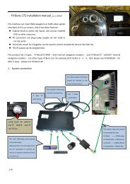
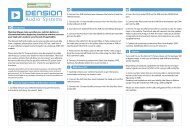
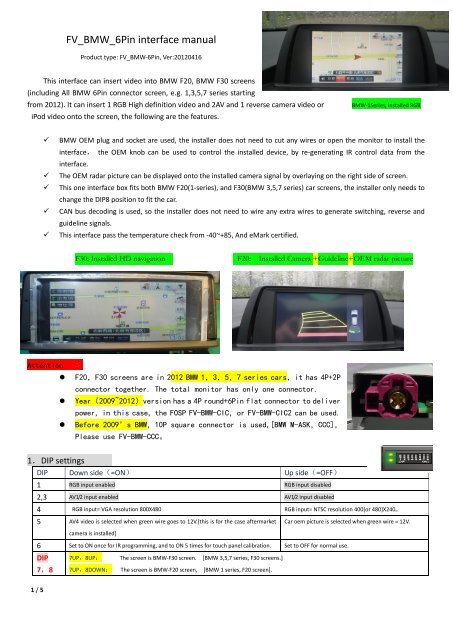
This <strong>interface</strong> can insert video into <strong>BMW</strong> F20, <strong>BMW</strong> F30 screens<br />
(including All <strong>BMW</strong> <strong>6Pin</strong> connector screen, e.g. 1,3,5,7 series starting<br />
from 2012). It can insert 1 RGB High definition video and 2AV and 1 reverse camera video or<br />
iPod video onto the screen, the following are the features.<br />
<strong>BMW</strong>‐1Series, installed RGB<br />
<br />
<br />
<br />
<br />
<br />
<strong>BMW</strong> OEM plug and socket are used, the installer does not need to cut any wires or open the monitor to install the<br />
<strong>interface</strong>, the OEM knob can be used to control the installed device, by re‐generating IR control data from the<br />
<strong>interface</strong>.<br />
The OEM radar picture can be displayed onto the installed camera signal by overlaying on the right side of screen.<br />
This one <strong>interface</strong> box fits both <strong>BMW</strong> F20(1‐series), and F30(<strong>BMW</strong> 3,5,7 series) car screens, the installer only needs to<br />
change the DIP8 position to fit the car.<br />
CAN bus decoding is used, so the installer does not need to wire any extra wires to generate switching, reverse and<br />
guideline signals.<br />
This <strong>interface</strong> pass the temperature check from ‐40~+85, And eMark certified.<br />
F30: Installed HD navigation F20: Installed Camera +Guideline+OEM radar picture<br />
Attention :<br />
• F20,F30 screens are in 2012 <strong>BMW</strong> 1,3,5,7 series cars,it has 4P+2P<br />
connector together. The total monitor has only one connector.<br />
• Year(2009~2012)version has a 4P round+<strong>6Pin</strong> flat connector to deliver<br />
power, in this case, the FOSP <strong>FV</strong>-<strong>BMW</strong>-CIC,or <strong>FV</strong>-<strong>BMW</strong>-CIC2 can be used.<br />
• Before 2009’s <strong>BMW</strong>,10P square connector is used,[<strong>BMW</strong> M-ASK,CCC],<br />
Please use <strong>FV</strong>-<strong>BMW</strong>-CCC。<br />
1.DIP settings<br />
DIP Down side(=ON) Up side(=OFF)<br />
1 RGB input enabled RGB input disabled<br />
2,3 AV1/2 input enabled AV1/2 input disabled<br />
4 RGB input= VGA resolution 800X480 RGB input= NTSC resolution 400[or 480]X240。<br />
5 AV4 video is selected when green wire goes to 12V.[this is for the case aftermarket<br />
Car oem picture is selected when green wire = 12V.<br />
camera is installed]<br />
6 Set to ON once for IR programming, and to ON 5 times for touch panel calibration. Set to OFF for normal use.<br />
DIP<br />
7,8<br />
7UP,8UP: The screen is <strong>BMW</strong>‐F30 screen. [<strong>BMW</strong> 3,5,7 series, F30 screens.]<br />
7UP,8DOWN: The screen is <strong>BMW</strong>‐F20 screen, [<strong>BMW</strong> 1 series, F20 screen].<br />
1 / 5
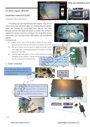
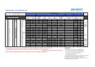
2. system connection:<br />
The OEM cable to monitor, should be<br />
inserted to the socket here, so the video<br />
go through the <strong>interface</strong>.<br />
DIP switch<br />
RGB Navi<br />
AV1/2<br />
AV1,AV2’s<br />
audio output<br />
Cam.<br />
MMI<br />
box<br />
The 6P LVDS output from<br />
<strong>interface</strong> should be inserted<br />
to the monitor’s socket.<br />
CAN box 4 input wires:<br />
• Blue CAN+ ‐‐‐‐to yellow/Red wire behind CD.<br />
• Gray CAN‐ ‐‐‐‐ to yellow/Gray wire behind CD.<br />
• Red with Fuse‐‐‐‐ to BATT,[Not ACC,or the user<br />
will see black screen if he turns on radio when<br />
ACC is off.]<br />
• Black‐‐‐‐‐‐‐to Ground Chassis。<br />
The 6PIN power connector signal definition between the Can box and <strong>interface</strong> box:<br />
YELLOW:power supply of 12V BATT。<br />
RED:generated ACC(=12V when key in ignition state):when=12V,the <strong>interface</strong> works.<br />
BLACK:Ground to Chassis。<br />
GREEN:Can box generated reverse trigger signal [when =12V the reverse video is enabled]<br />
WHITE:Can box generated switch signal wire, when=12V, this <strong>interface</strong> switches。[max.25V]<br />
GRAY:CAN box’s <strong>com</strong>munication with <strong>interface</strong> on sharing control signal to DVD/TV on this wire.[if we do<br />
not need to idrv to control DVD/TV/iPOD, this wire may be cut off.]<br />
2 / 5
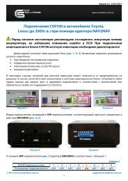
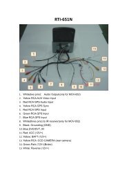
3. operations:<br />
‣ menu: when pressed long, the <strong>interface</strong> will switch among the enabled inputs of<br />
RGB, AV1, AV2.<br />
‣ Audio:when pressed, the video will always go back to OEM picture.<br />
‣ Option: when the screen is 24:9, that is <strong>BMW</strong> 3,5,7 series),this button when<br />
pressed will toggle the display mode among 16:9 and 24:9.<br />
Option<br />
‣ The rotation of knob: when rotated, the MMI icons will pop up,<br />
and the user can select the wanted function to control the installed<br />
DVD or TV.<br />
‣ Right-Push of the knob:when the icons pop up, the user right-push<br />
the knob will execute the selected icon and IR code will be sent out.<br />
4. the 3 side key buttons<br />
The input box has 3 side keys, the installer<br />
may use it to tune the picture display, and touch<br />
function for the connected DVD or other devices.<br />
The 3 keys are : menu, +, ‐.<br />
The first 5 options has separate state memory.<br />
The modification of one input is different , and it<br />
does not affecting other inputs.<br />
• The 3 side keys are : menu, +,‐ respectively. When menu is press, OSD strings will pop up on screen, and the installer<br />
may adjust the best video effect. The +/‐ will change the value.<br />
• The brightness/contrast/saturation tunes the color of the current video input.<br />
• The H position,V position sets the image position on screen.<br />
• The DVD/TUNER/NAVI is to set the IR code output to the installed device, so people use original knob to control<br />
• When set to “none”,the control icons will not pop out<br />
• When set to “Prog”,the installer can use DIP6=Down to program the IR code into the <strong>interface</strong>, so extra new devices<br />
can be controlled.<br />
The last option: “Guide Line……ON”: the installer can set ON/OFF to<br />
enable the parking guide line, which shows the safe zone when<br />
parking.<br />
3 / 5
The programming of IR code:<br />
‣ There are >10 types of DVD, NAVI, and Tuners’ IR code are stored inside the <strong>interface</strong>. The installer just adjusts the options to select to<br />
wanted one, then it works. If the wanted type is not there, he may set the option to be “Prog” in the menu.<br />
‣ When programming, switch the input to AV1, and set DIP6 down once, then the control icons will be shown, and one of the them will<br />
be blinking. Point the IR remote controller to the IR port of <strong>interface</strong>, the blinking icon will be moved to the next one. Which means<br />
one code is programmed. Repeat this step until all icons are programmed.<br />
The gray wire of the 6P power connector is the same as IR‐data wire, it can be connected to ir sensor‐signal to program IR as well.<br />
‣ The programming of AV2 is the same as above.<br />
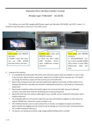
5. The Ctrl port.<br />
Ctrl port here.<br />
The Ctrl port has 8 pins, it is not necessary for the installers to use it in most cases, however it can be used for<br />
installer’s convenience in case many more extra devices are installed.<br />
Pin 1,<br />
Pin2<br />
+5V output voltage for sound switch<br />
relay when AV1 is selected,<br />
0V when AV2 selected.<br />
This pin can pull the relay with +5V.<br />
[max output=2A, while most mechanical relay only needs<br />
0.1~0.3A.]<br />
Pin3: constant +5V when the unit is working. max 2A output.<br />
Pin 4,8 GND It is tied to GND inside.<br />
Pin 5: data bus for touch screen Pin5,6 should NOT be connected to GND, because it will halt<br />
Pin 6: clock bus for touch screen.<br />
the CPU inside. Leave it open for normal use.<br />
Pin 7 +5V output voltage for touch screen<br />
switch relay,<br />
when in inserted video mode, this<br />
pin=5V, when in original car<br />
video mode, this pin=0V.<br />
For imported cars which needs touch screen for installed<br />
navigation <strong>com</strong>puter, this voltage can be used to switch the<br />
original touch screen.<br />
max 2A output.<br />
4 / 5
6. Parameters<br />
No. name parameter<br />
1 RGB video amplitude 0.7Vpp with 75 ohm impedance<br />
2 sync amplitude in RGB‐navi port 3~5Vpp with 5K ohm impedance<br />
Sync should be NTSC <strong>com</strong>posite with negative polarity.<br />
When in VGA mode, the Hsync and Vsync should be <strong>com</strong>bined by a 74HC86 to make<br />
a Composite sync.[Xor operation], it can be XOR with ‘1’ to get inverted to negative<br />
polarity.<br />
3 RGB resolution NTSC‐RGB navigation, that is. 320X240,400X240,480X240<br />
Or VGA resolution[640X480 or 800X480]<br />
4 Av1,Av2, cam video 0.7Vpp with 75 ohm impedance<br />
NTSC/PAL/SECAM automatic switch<br />
5 IR RGB, IR_AV1 output 3.3V digital infrared control code with 4 data bytes<br />
[machine code1,machine code 2, user code, verification code]<br />
6 Normal Power consumption 2.4W [0.2A @12V]<br />
7 Standby current < 10uA<br />
8 Reverse trigger threshold >5V trigger<br />
9 Ctrl port Pin1,2 and Pin7:<br />
Output voltage<br />
Relay pull voltage for Audio and touch screen selection<br />
5V volts.<br />
10 Ctrl port Pin1,2 and Pin7:<br />
Current<br />
2A. Tested to have no damage when short‐circuit to GND for 2<br />
minutes. Leave it open when do not use.<br />
11 Work temperature ‐40 ~ +85C<br />
5 / 5