Mercedes W212 interface Installer's manual [Product type: FV ...
Mercedes W212 interface Installer's manual [Product type: FV ...
Mercedes W212 interface Installer's manual [Product type: FV ...
- No tags were found...

Create successful ePaper yourself
Turn your PDF publications into a flip-book with our unique Google optimized e-Paper software.
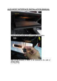
<strong>Mercedes</strong> <strong>W212</strong> <strong>interface</strong> Installer’s <strong>manual</strong><br />
[<strong>Product</strong> <strong>type</strong>: <strong>FV</strong>‐Benz567<br />
Ver.10.05]<br />
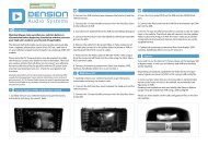
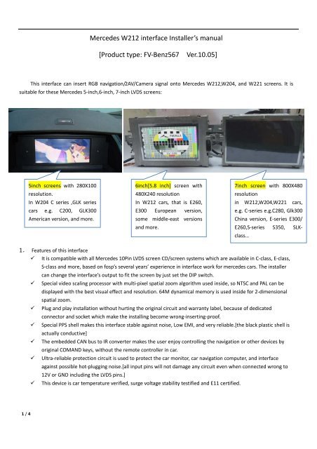
This <strong>interface</strong> can insert RGB navigation/2AV/Camera signal onto <strong>Mercedes</strong> <strong>W212</strong>,W204, and W221 screens. It is<br />
suitable for these <strong>Mercedes</strong> 5‐inch,6‐inch, 7‐inch LVDS screens:<br />
5inch screens with 280X100<br />
resolution.<br />
In W204 C series ,GLK series<br />
cars e.g. C200, GLK300<br />
American version, and more.<br />
6inch[5.8 inch] screen with<br />
480X240 resolution<br />
In <strong>W212</strong> cars, that is E260,<br />
E300 European version,<br />
some middle‐east versions<br />
and more.<br />
7inch screen with 800X480<br />
resolution<br />
in <strong>W212</strong>,W204,W221 cars,<br />
e.g. C‐series e.g.C280, Glk300<br />
China version, E‐series E300/<br />
E260,S‐series S350, SLKclass…<br />
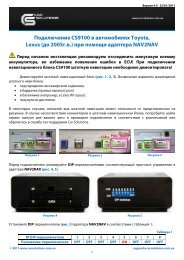
1. Features of this <strong>interface</strong><br />
It is compatible with all <strong>Mercedes</strong> 10Pin LVDS screen CD/screen systems which are available in C‐class, E‐class,<br />
S‐class and more, based on fosp’s several years’ experience in <strong>interface</strong> work for mercedes cars. The installer<br />
can change the <strong>interface</strong>’s output to fit the screen by just set the DIP switch.<br />
Special video scaling processor with multi‐pixel spatial zoom algorithm used inside, so NTSC and PAL can be<br />
displayed with the best visual effect and resolution. 64M dynamical memory is used inside for 2‐dimensional<br />
spatial zoom.<br />
Plug and play installation without hurting the original circuit and warranty label, because of dedicated<br />
connector and socket which make the installing become wrong‐inserting‐proof.<br />
Special PPS shell makes this <strong>interface</strong> stable against noise, Low EMI, and very reliable.[the black plastic shell is<br />
actually conductive]<br />
The embedded CAN bus to IR converter makes the user enjoy controlling the navigation or other devices by<br />
original COMAND keys, without the remote controller in car.<br />
Ultra‐reliable protection circuit is used to protect the car monitor, car navigation computer, and <strong>interface</strong><br />
against possible hot‐plugging noise.[all input pins will not damage any circuit even when connected wrong to<br />
12V or GND including the LVDS pins.]<br />
This device is car temperature verified, surge voltage stability testified and E11 certified.<br />
1 / 4
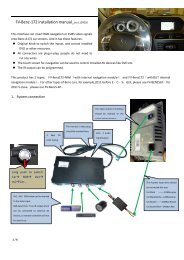
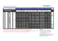
2.System connection<br />
DIP switch setting:<br />
DIP =ON [DIP=Down side.] =OFF<br />
1 RGB enabled RGB disabled.<br />
2, AV1 for DVD enabled AV1 disabled<br />
3 AV2 for Tuner/MP5 or extra video enabled AV2disabled<br />
5 This is reverse camera trigger wire<br />
go to CAM when Green wire= 12V]<br />
go to car video when Green wire= 12V<br />
6 NAVIGATION= VGA NAVIGATION=RGB NTSC<br />
7,8 7=UP,8=UP: 7inch screen with 800X480 resolution<br />
7=UP,8=DOWN:<br />
7=DOWN,8=DOWN:<br />
6inch screen with 480X240 resolution<br />
5inch screen with 280X100 resolution<br />
navigation<br />
3 keys for color<br />
tuning in CVBS<br />
AV1/2<br />
TV/DVD<br />
The 1Meter “to <strong>interface</strong>” cable<br />
should be connected to the<br />
camera<br />
daughter box and LVDS_OUT<br />
socket.<br />
Can box<br />
The “Monitor cable in” socket<br />
should be inserted with original<br />
video cable for screen.<br />
The 20cm “to monitor socket”<br />
cable should be inserted back to<br />
the monitor’s video socket<br />
• Long pull the knob for 1second<br />
will switch inputs:Car RGB<br />
AV1 av2car…<br />
• Press C to switch to RGB‐navi<br />
when in car video mode.<br />
2 / 4
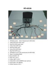
Note:<br />
<br />
The DIP switches can be changed anytime, the installer do not need to<br />
switch the unit off to change the DIP.<br />
The DIP7,8 is related to the output picture resolution, when Set<br />
Wrong, nothing will be damaged, just reset to correct state.<br />
[see here if the DIP is set 400X240 while the car screen is<br />
actually 800X480.]<br />
The 3 side key switches:<br />
The 3 side keys are : menu, +,‐ respectively. When menu is press, this OSD<br />
strings will pop up on screen, and the installer may adjust the Brightness/<br />
Contrast/ Saturation/Sharpness to set the best video effect. The +/‐ will<br />
change the value.<br />
[this menu will not pop out in RGB input state because it is tuned to be<br />
the best resolution and displayed effect already.]<br />
<br />
The DVD/TUNER/NAVI selection in the OSD menu gives the option for the<br />
installer to select various brands of DVD, TV‐tuner, and navigation computer.<br />
These devices can be controlled by the <strong>interface</strong>’s internal CAN bus to IR<br />
converter. So remote controllers are not needed for the viewer.<br />
The installer can use the original command knob to select the command,<br />
or add the extra touch screen to control the DVD.<br />
If the viewer do not care using a remote control for DVD and extra video device, the last 3 options may be<br />
not cared about.<br />
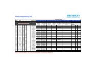
3. 4Pin CAN box input wires connection:<br />
Name Color in Car connector[8PIN] Color in CAN‐BOX[4Pin]<br />
CAN ‐ Twitsted BLACK twisted orange<br />
CAN + Twitsted BLACK/WHITE twisted BLUE<br />
GND BROWN BROWN<br />
BATT [13.8V] RED /Blue RED with 2A FUSE<br />
[note:<br />
1. CAN wrong connection is not hurting device, the LED will be blinking when connected correctly。<br />
2. The CAN wire location may be different from C‐class to E‐class and GLK, but the color in the above<br />
table is always correct.]<br />
3 / 4<br />
The 6P wire conn. between CAN–Interface box :<br />
YELLOW: 12V battery power<br />
RED=ACC:when screen is On this wire goes to 12V.<br />
BLACK:Ground for chassis。<br />
GREEN:reverse wire[=12V]。<br />
white: switch signal when =12V.[max 25V]<br />
GRAY: specific control signal from the CAN box.
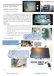
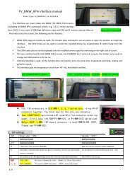
3. The Ctrl port switch.<br />
Ctrl port here.<br />
Audio AUX inside here.<br />
The Ctrl port has 8 pins, it is not necessary for the installers to use it in most<br />
cases, however it can be used for in cased it is needed.<br />
All <strong>Mercedes</strong> cars have an AUX input, which can be connected to the external audio input. This aux input<br />
locates inside the front trunk as shown in this picture.<br />
If the installer needs to send 2 or more extra audio into the car speaker, one mechanical relay can be used to<br />
switch the sound. The Ctrl.port on the <strong>interface</strong> has a 5V switch voltage. [max output=2A, while most mechanical<br />
relay only needs 0.1~0.3A.]<br />
Pin 1: +5V output voltage for sound‐switch‐relay when AV1<br />
is selected, 0V when AV2 selected.<br />
Pin 4: GND<br />
Pin 8: GND<br />
Pin 5: data bus for touch screen<br />
Pin 6: clock bus for touch screen.<br />
‣ Pin1,5,6 has high voltage protection inside in case<br />
wrongly connected to 12V by installer.[max 25V].<br />
‣ Pin5,6 should NOT be connected to GND.<br />
4. Parameters<br />
No. name parameter<br />
1 RGB video amplitude 0.7Vpp with 75 ohm impedance<br />
2 sync amplitude in RGB‐navi port 3~5Vpp with 5K ohm impedance<br />
Sync should be NTSC composite with negative polarity.<br />
3 Av1,Av2, cam video amplitude 0.7Vpp with 75 ohm impedance<br />
4 Av1,Av2, cam standard NTSC/PAL/SECAM automatic switch<br />
5 VGA Suggested to be 800X600@60Hz<br />
when VGA: Pin 1,2,3,4,8 carry R,G,B, Hsync, Vsync respectively.<br />
VGA mode is only available for 800X480 screen, for 6 and 5‐inch<br />
low resolution screen, it shows screen.<br />
6 Normal work Power consumption 2.4W [0.2A @12V]<br />
7 Standby current < 5mA<br />
8 Standby start 10 seconds after the users switch off the CD unit.<br />
9 Reverse trigger threshold >5V trigger<br />
10 Work temperature ‐40 ~ +85C<br />
4 / 4