IP 67 modular I/O splitter boxes for fieldbuses
IP 67 modular I/O splitter boxes for fieldbuses
IP 67 modular I/O splitter boxes for fieldbuses

Create successful ePaper yourself
Turn your PDF publications into a flip-book with our unique Google optimized e-Paper software.
Presentation 5<br />
<strong>IP</strong><br />
<strong>67</strong> <strong>modular</strong> I/O <strong>splitter</strong> <strong>boxes</strong><br />
<strong>for</strong> <strong>fieldbuses</strong> 5<br />
Advantys, FTM <strong>splitter</strong> <strong>boxes</strong><br />
Presentation<br />
To meet the needs of machine manufacturers and users, automation system<br />
architectures are becoming decentralised, while offering per<strong>for</strong>mances comparable<br />
to those obtained with a centralised structure.<br />
Advantys FTM <strong>IP</strong> <strong>67</strong> <strong>modular</strong> I/O <strong>splitter</strong> <strong>boxes</strong> enable sensors and actuators to be<br />
connected in distributed automation systems using pre-assembled cables, thus<br />
reducing wiring time and costs, whilst at the same time increasing the operational<br />
availability of the installation.<br />
These <strong>IP</strong> <strong>67</strong> protected <strong>splitter</strong> <strong>boxes</strong> can also be used within processes or machines<br />
in harsh environments (splashing water, oil, dust, etc.).<br />
Advantys FTM <strong>splitter</strong> <strong>boxes</strong> allow distributed connection of sensors and actuators<br />
on machines via a fieldbus. They communicate on different buses such as:<br />
CANopen, DeviceNet and Profibus-DP.<br />
Sensors and actuators are connected by means of standard M12 and M8<br />
connectors.<br />
This <strong>modular</strong>ity makes installation of the <strong>splitter</strong> <strong>boxes</strong> within the machine even<br />
easier.<br />
The configurable I/O <strong>splitter</strong> <strong>boxes</strong> also enable the mixing of inputs and outputs and,<br />
as a result, reduce the number of product variants. This provides savings in space<br />
as well as increasing the flexibility of the installation.<br />
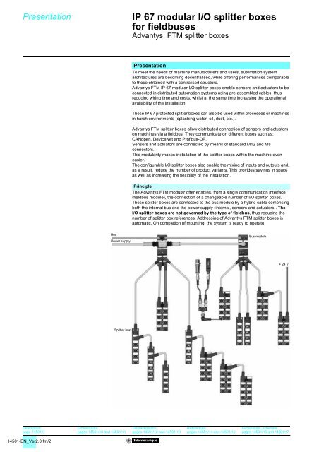
Principle<br />
The Advantys FTM <strong>modular</strong> offer enables, from a single communication interface<br />
(fieldbus module), the connection of a changeable number of I/O <strong>splitter</strong> <strong>boxes</strong>.<br />
These <strong>splitter</strong> <strong>boxes</strong> are connected to the bus module by a hybrid cable comprising<br />
both the internal bus and the power supply (internal, sensors and actuators). The<br />
I/O <strong>splitter</strong> <strong>boxes</strong> are not governed by the type of fieldbus, thus reducing the<br />
number of <strong>splitter</strong> box references. Addressing of Advantys FTM <strong>splitter</strong> <strong>boxes</strong> is<br />
automatic. On completion of mounting, the system is ready to operate.<br />
Bus<br />
Power supply<br />
Bus module<br />
+24V<br />
Splitter box<br />
Description:<br />
page 14501/9<br />
Connections:<br />
pages 14501/10 and 14501/11<br />
Characteristics:<br />
pages 14501/12 and 14501/13<br />
References:<br />
pages 14501/14 and 14501/15<br />
Dimensions, schemes:<br />
pages 14501/16 and 14501/17<br />
14501-EN_Ver2.0.fm/2
Presentation (continued) 5<br />
<strong>IP</strong><br />
<strong>67</strong> <strong>modular</strong> I/O <strong>splitter</strong> <strong>boxes</strong><br />
<strong>for</strong> <strong>fieldbuses</strong> 5<br />
Advantys, FTM <strong>splitter</strong> <strong>boxes</strong><br />
Segment 4<br />
Segment 3<br />
Segment 2<br />
5 m max. (1)<br />
Segment 1<br />
4 <strong>splitter</strong> <strong>boxes</strong> max.<br />
4 <strong>splitter</strong> <strong>boxes</strong> max.<br />
Presentation (continued)<br />
The topology of the system is a star/line architecture.<br />
Each bus module is fitted with four M12 connectors <strong>for</strong> the connection of<br />
Advantys FTM <strong>splitter</strong> <strong>boxes</strong> (star architecture). On each “run”, called a segment, it<br />
is possible to connect up to 4 <strong>splitter</strong> <strong>boxes</strong> on the chaining principle (line<br />
architecture). The maximum length of a segment, between the bus module and the<br />
last <strong>splitter</strong> box, must not exceed 5 metres.<br />
For one bus module, the maximum number of <strong>splitter</strong> <strong>boxes</strong> is:<br />
b 4 per segment, i.e. 64 I/O.<br />
b 16 <strong>for</strong> the group of 4 possible segments of the bus module, i.e. 256 digital I/O.<br />
Several Advantys FTM <strong>splitter</strong> box variants are available:<br />
Compact <strong>splitter</strong> <strong>boxes</strong><br />
These <strong>splitter</strong> <strong>boxes</strong> do not allow continuity of the internal bus to other <strong>splitter</strong> <strong>boxes</strong><br />
on the same bus module segment. They are used in the following cases:<br />
- a single <strong>splitter</strong> box on a segment (no chaining),<br />
- the last <strong>splitter</strong> box on a segment.<br />
4 <strong>splitter</strong> <strong>boxes</strong> max.<br />
Expandable <strong>splitter</strong> <strong>boxes</strong><br />
These <strong>splitter</strong> <strong>boxes</strong> allow continuity of the internal bus to other <strong>splitter</strong> <strong>boxes</strong><br />
(chaining). If an expandable <strong>splitter</strong> box is used as the last <strong>splitter</strong> box of an internal<br />
bus segment, it is then necessary to install a line terminator on the output bus<br />
connector.<br />
4 <strong>splitter</strong> <strong>boxes</strong> max.<br />
(1) Maximum distance of 5 m between the bus module<br />
and the last <strong>splitter</strong> box on the same segment.<br />
Digital I/O <strong>splitter</strong> <strong>boxes</strong><br />
These <strong>splitter</strong> <strong>boxes</strong> are available in compact and expandable versions, only <strong>for</strong> the<br />
connection of sensors (input <strong>splitter</strong> <strong>boxes</strong>) or <strong>for</strong> the connection of sensors and/or<br />
actuators (input/output <strong>splitter</strong> <strong>boxes</strong>):<br />
- c 24 V inputs, IEC type 2.<br />
- c 24 V 0.5 A transistor outputs.<br />
b The different input <strong>splitter</strong> box variants are as follows:<br />
v 8 x M8 connectors <strong>for</strong> connection of up to 8 sensors,<br />
v 4 x M12 connectors <strong>for</strong> connection of up to 8 sensors (4 <strong>for</strong> sensors with integrated<br />
DESINA diagnostics function),<br />
v 8 x M12 connectors <strong>for</strong> connection of up to 16 sensors (8 <strong>for</strong> sensors with<br />
integrated DESINA diagnostics function).<br />
b The different input/output <strong>splitter</strong> box variants are as follows:<br />
Each channel can be configured as an input, an output or as a diagnostic input.<br />
v 8 x M8 connectors <strong>for</strong> connection of up to 8 sensors or actuators,<br />
v 4 x M12 connectors <strong>for</strong> connection of up to 8 sensors or actuators (4 <strong>for</strong> sensors<br />
with integrated DESINA diagnostics function),<br />
v 8 x M12 connectors <strong>for</strong> connection of up to 16 sensors or actuators (8 <strong>for</strong> sensors<br />
or actuators with integrated DESINA diagnostics function).<br />
Analogue I/O <strong>splitter</strong> <strong>boxes</strong><br />
These <strong>splitter</strong> <strong>boxes</strong> are only available in the compact version <strong>for</strong> the connection of<br />
analogue sensors or actuators using M12 connectors:<br />
b 4 analogue input <strong>splitter</strong> <strong>boxes</strong> (voltage or current).<br />
b 4 analogue output <strong>splitter</strong> <strong>boxes</strong> (voltage or current).<br />
Description:<br />
page 14501/9<br />
Connections:<br />
pages 14501/10 and 14501/11<br />
Characteristics:<br />
pages 14501/12 and 14501/13<br />
References:<br />
pages 14501/14 and 14501/15<br />
Dimensions, schemes:<br />
pages 14501/16 and 14501/17<br />
14501-EN_Ver2.0.fm/3
Functions 5<br />
<strong>IP</strong><br />
<strong>67</strong> <strong>modular</strong> I/O <strong>splitter</strong> <strong>boxes</strong><br />
<strong>for</strong> <strong>fieldbuses</strong> 5<br />
Advantys, FTM <strong>splitter</strong> <strong>boxes</strong><br />
Functions<br />
Selection of signal type per channel<br />
b Each M12, 5-pin connector on Advantys FTM <strong>splitter</strong> <strong>boxes</strong> allows the connection<br />
of 2 signals. Depending on the type of <strong>splitter</strong> box, these can be:<br />
v 1 sensor input signal,<br />
v 1 diagnostic input signal,<br />
v 1 actuator output signal.<br />
Signal type, depending on digital <strong>splitter</strong> box selected:<br />
FTM 1DD<br />
FTM 1DE<br />
M12 and M8 Contact 4 Input<br />
Output<br />
Input<br />
M12 Contact 2 Input<br />
Output<br />
Diagnostic<br />
Input<br />
Diagnostic<br />
Note: either a normally open (N/O) or a normally closed (N/C) contact can be chosen <strong>for</strong> each<br />
input signal.<br />
Diagnostics<br />
Each Advantys FTM <strong>splitter</strong> box has one LED per channel to indicate the status of<br />
the channel and to enable fast and precise location of a fault. Fault monitoring<br />
diagnostics are indicated on the <strong>splitter</strong> box by LEDs and are fed back to the control<br />
system (PLC) via the bus.<br />
There are 2 levels of diagnostics:<br />
b diagnostics per channel,<br />
b diagnostics per <strong>splitter</strong> box.<br />
Diagnostics per channel<br />
b Sensor short-circuit<br />
A short-circuit or overload on contact 1 of the M12 or M8 female connector blows<br />
the self-resetting fuse. Each M12 or M8 connector is individually protected. A red<br />
LED indicates the fault on the corresponding M12 or M8 connector. This fault is<br />
signalled to the Master. Supply to the sensors is automatically restored after<br />
elimination of the fault.<br />
b Actuator short-circuit<br />
A short-circuit or overload of an output causes a reset of this output. The fault is<br />
signalled to the Master. A red LED indicates the fault on the corresponding M12 or<br />
M8 connector. The output does not restart automatically. After having eliminated the<br />
cause of the fault, the channel must be reset by the PLC. This operation erases the<br />
short-circuit memory.<br />
b Actuator warning<br />
When the output is at state 0, the contact corresponding to the M12 or M8 female<br />
connector is checked <strong>for</strong> presence of 24 V voltage. If + 24 V is present, it means<br />
there is a “short-circuit”. A red LED indicates the fault on the corresponding M12 or<br />
M8 connector. The fault is signalled to the Master.<br />
Description:<br />
page 14501/9<br />
Connections:<br />
pages 14501/10 and 14501/11<br />
Characteristics:<br />
pages 14501/12 and 14501/13<br />
References:<br />
pages 14501/14 and 14501/15<br />
Dimensions, schemes:<br />
pages 14501/16 and 14501/17<br />
14501-EN_Ver2.0.fm/4
Functions (continued) 5<br />
<strong>IP</strong><br />
<strong>67</strong> <strong>modular</strong> I/O <strong>splitter</strong> <strong>boxes</strong><br />
<strong>for</strong> <strong>fieldbuses</strong> 5<br />
Advantys, FTM <strong>splitter</strong> <strong>boxes</strong><br />
Functions (continued)<br />
Diagnostics per <strong>splitter</strong> box<br />
b Sensor/actuator supply status.<br />
b “Undervoltage” fault on the I/O supply.<br />
b Sensor short-circuit.<br />
b Actuator short-circuit.<br />
Example of connection of a sensor with integrated diagnostics<br />
function<br />
M12<br />
connector<br />
1<br />
2 Diagnostic<br />
3<br />
4 (S)<br />
Example of connection of a standard sensor with the<br />
diagnostics adaptor<br />
M12<br />
connector<br />
1<br />
2 Diagnostic<br />
M12 adaptor<br />
FTX DG12<br />
(by-pass)<br />
1<br />
DESINA<br />
sensor<br />
Use of contact 2 diagnostics function (M12 connector)<br />
Advantys FTM <strong>splitter</strong> <strong>boxes</strong> allow the use of sensors and actuators incorporating an<br />
integrated diagnostics function (DESINA type). Configuring contact 2 of each M12<br />
connector as a diagnostic input enables detection of external faults associated with<br />
the sensors or actuators.<br />
This in<strong>for</strong>mation enables the following faults to be detected:<br />
b damage to the detection surface,<br />
b faulty electronics,<br />
b no load.<br />
Selection of either the sensor input or diagnostic input function on contact 2 is made<br />
channel by channel, by entering parameters, when configuring the <strong>splitter</strong> box.<br />
Fault indication by a red LED is possible <strong>for</strong> each channel configured as a diagnostic<br />
input.<br />
Example of connection of a sensor with integrated diagnostics function:<br />
Using the M12 diagnostics adaptor accessory FTX DG12, it is possible to monitor<br />
breaks in wiring to sensors or actuators which do not have an integrated diagnostics<br />
function (only applicable to <strong>splitter</strong> <strong>boxes</strong> fitted with M12 connectors).<br />
3<br />
4 (S)<br />
3<br />
4 (S)<br />
Sensor<br />
Description:<br />
page 14501/9<br />
Connections:<br />
pages 14501/10 and 14501/11<br />
Characteristics:<br />
pages 14501/12 and 14501/13<br />
References:<br />
pages 14501/14 and 14501/15<br />
Dimensions, schemes:<br />
pages 14501/16 and 14501/17<br />
14501-EN_Ver2.0.fm/5
Presentation (continued),<br />
configuration 5<br />
<strong>IP</strong> <strong>67</strong> <strong>modular</strong> I/O <strong>splitter</strong> <strong>boxes</strong><br />
<strong>for</strong> <strong>fieldbuses</strong> 5<br />
Advantys, FTM <strong>splitter</strong> <strong>boxes</strong><br />
CANopen bus presentation<br />
Premium<br />
Other Master<br />
CANopen bus<br />
From 1 to 127 Slaves<br />
ATV 58<br />
TeSys<br />
Model U<br />
Tego Power<br />
FTM 1CN<br />
FTM 1CN<br />
The CAN system, initially developed <strong>for</strong> real-time exchange of in<strong>for</strong>mation in the<br />
automobile industry, is now being used more and more throughout industry. There<br />
are several <strong>fieldbuses</strong> based on CAN base layers and components.<br />
The CANopen bus con<strong>for</strong>ms to international standard ISO 11898, promoted by the<br />
“CAN in Automation” association (a grouping of manufacturers and users), and<br />
guarantees a high degree of openness and inter-operability due to its communication<br />
profiles and its standardised equipment.<br />
The CANopen bus is now recognised, in Europe, as the reference standard <strong>for</strong><br />
building industrial systems based on the CAN concept.<br />
The CANopen bus is a Multimaster bus, based on the Master/Slave principle.<br />
The physical link consists of a shielded twisted pair, to which up to a maximum of<br />
127 Slaves can be connected by simple tap-off. The binary rate varies, depending<br />
on the length of the bus, from 1 M bits/s <strong>for</strong> 40 m to 50 K bits/s <strong>for</strong> 1000 m.<br />
Each end of the bus must be fitted with a line terminator.<br />
The CANopen bus is a set of profiles on CAN systems, possessing the following<br />
characteristics:<br />
b Open bus system.<br />
b Data exchanges in real-time without overloading the protocol.<br />
b Modular design allowing modification of size.<br />
b Interconnection and interchangeability of devices.<br />
b Standardised configuration of networks.<br />
b Access to all device parameters.<br />
b Synchronisation and circulation of data from cyclic and/or event-controlled<br />
processes (short system response time).<br />
b Exchanges possible with numerous international manufacturers.<br />
CANopen bus configuration<br />
A .eds file is assigned to each product, which contains all the important in<strong>for</strong>mation<br />
relating to the product. An icon (.dib) is also available <strong>for</strong> installation in the system<br />
configurator.<br />
Please refer to the configuration software documentation <strong>for</strong> the import of .eds files.<br />
Following the CANopen system initialisation phase, all the Slaves signal their<br />
presence on the bus by means of a “Boot-Up” message. A setting-up configurator<br />
(e.g.: SyCon. Refer to our Modicon Premium automation plat<strong>for</strong>m catalogue) can<br />
then start to read and register the CANopen bus and, on the basis of the data<br />
obtained, assign a corresponding .eds file to each Slave. Based on the .eds file data,<br />
the Master creates a peripheral image of all the Slaves detected by the PLC. The<br />
user can assign I/O bytes to logic addresses within the PLC.<br />
b Addressing<br />
The addresses are configurable from 1 to 99 by means of 2 coding wheels (x 10 and<br />
x 1). A 3rd coding wheel enables the data transmission speed to be selected<br />
(position 0 = automatic speed recognition).<br />
Description:<br />
page 14501/9<br />
Connections:<br />
pages 14501/10 and 14501/11<br />
Characteristics:<br />
pages 14501/12 and 14501/13<br />
References:<br />
pages 14501/14 and 14501/15<br />
Dimensions, schemes:<br />
pages 14501/16 and 14501/17<br />
14501-EN_Ver2.0.fm/6
Presentation (continued),<br />
configuration 5<br />
<strong>IP</strong> <strong>67</strong> <strong>modular</strong> I/O <strong>splitter</strong> <strong>boxes</strong><br />
<strong>for</strong> <strong>fieldbuses</strong> 5<br />
Advantys, FTM <strong>splitter</strong> <strong>boxes</strong><br />
DeviceNet bus presentation<br />
Premium<br />
Other Master<br />
DeviceNet bus<br />
From 1 to 63 Slaves<br />
ATV 58<br />
TeSys<br />
Model U<br />
Momentum<br />
Tego Power<br />
FTM 1DN<br />
FTM 1DN<br />
The DeviceNet system is a sensor/actuator bus system of the open Low-End type,<br />
used in various industrial applications and, in particular, the automobile industry. It is<br />
based on CAN technology (OSI layers 1 and 2).<br />
The DeviceNet bus is based on the Master/Slave principle.<br />
The physical link consists of 2 shielded twisted pairs (2 wires <strong>for</strong> data, 2 wires <strong>for</strong><br />
auxiliary supply to sensors), to which up to a maximum of 63 slaves can be<br />
connected. The binary rate varies, depending on the length of the bus, from 125 K<br />
bits/s <strong>for</strong> 500 m to 500 K bits/s <strong>for</strong> 100 m.<br />
Each end of the bus must be fitted with a line terminator.<br />
DeviceNet bus configuration<br />
A .eds file is assigned to each product, which contains all the important in<strong>for</strong>mation<br />
relating to the product. An icon (.ico) is also available <strong>for</strong> installation in the system<br />
configurator.<br />
When the network is scanned, the identification data is compared with that of the<br />
Slaves present on the network and assigned accordingly. After the scanning phase,<br />
the scanner will have identified all the Slaves and saved in<strong>for</strong>mation relating to data<br />
length and operating mode.<br />
The DeviceNet bus Master establishes a peripheral image of all the devices detected<br />
on the DeviceNet bus and incorporates them according to their physical location in a<br />
Scan list. The user can then assign the Scan list, according to the peripheral image<br />
of the bus devices, to logic addresses in the PLC.<br />
b Addressing<br />
The addresses are configurable from 1 to 63 by means of 2 coding wheels (x 10 and<br />
x 1). A 3rd coding wheel enables the data transmission speed to be selected<br />
(3 speeds can be selected: 125, 250 and 500 K bits/s).<br />
Description:<br />
page 14501/9<br />
Connections:<br />
pages 14501/10 and 14501/11<br />
Characteristics:<br />
pages 14501/12 and 14501/13<br />
References:<br />
pages 14501/14 and 14501/15<br />
Dimensions, schemes:<br />
pages 14501/16 and 14501/17<br />
14501-EN_Ver2.0.fm/7
Presentation 5<br />
<strong>IP</strong><br />
<strong>67</strong> <strong>modular</strong> I/O <strong>splitter</strong> <strong>boxes</strong><br />
<strong>for</strong> <strong>fieldbuses</strong> 5<br />
Advantys, FTM <strong>splitter</strong> <strong>boxes</strong><br />
Profibus-DP presentation<br />
Quantum<br />
Other Master<br />
Premium<br />
Profibus-DP bus<br />
ATV 58E<br />
Momentum<br />
FTM 1DP<br />
FTM 1DP<br />
FTM 1DP<br />
FTM 1DP<br />
The Profibus-DP (Process Fieldbus Decentralized Peripheral) is an open type<br />
fieldbus system <strong>for</strong> industrial applications. The Profibus standard is described in<br />
standard EN 50170.<br />
The physical link is a simple, type A, shielded twisted pair.<br />
Data exchange between the Master (processing unit) and the Slaves (decentralised<br />
devices) is per<strong>for</strong>med in a cyclic manner.<br />
A maximum of 32 Slaves can be connected to a bus segment. To increase the<br />
maximum number of Slaves possible, repeaters must be installed in order to create<br />
new bus segments.<br />
The repeaters also provide galvanic isolation of the bus segments.<br />
The total number of slaves must not exceed 126.<br />
The bus must be fitted with a line terminator at each end of each segment created.<br />
Description:<br />
page 14501/9<br />
Connections:<br />
pages 14501/10 and 14501/11<br />
Characteristics:<br />
pages 14501/12 and 14501/13<br />
References:<br />
pages 14501/14 and 14501/15<br />
Dimensions, schemes:<br />
pages 14501/16 and 14501/17<br />
14501-EN_Ver2.0.fm/8
Description 5<br />
<strong>IP</strong><br />
<strong>67</strong> <strong>modular</strong> I/O <strong>splitter</strong> <strong>boxes</strong><br />
<strong>for</strong> <strong>fieldbuses</strong> 5<br />
Advantys, FTM <strong>splitter</strong> <strong>boxes</strong><br />
1<br />
12 2<br />
6<br />
3<br />
8<br />
9<br />
4<br />
5<br />
7<br />
Description<br />
Modular bus modules FTM have the following on the front face:<br />
1 One M12 male connector (bus IN) <strong>for</strong> connection of the bus.<br />
2 One M12 female connector (bus OUT) <strong>for</strong> connection of the bus.<br />
3 One 7/8 male connector <strong>for</strong> connection of the c 24 V power supplies.<br />
4 Four M12 female connectors <strong>for</strong> connection of the <strong>splitter</strong> box inputs/outputs via<br />
the internal bus.<br />
5 Four channel marker labels.<br />
6 Two bus module marker labels.<br />
7 Speed selection (CANopen and DeviceNet buses) and bus address switches.<br />
8 One bus power supply status LED.<br />
9 One bus diagnostics LED.<br />
10 One sensor power supply diagnostics LED.<br />
11 One sensor power supply diagnostics and communication status LED.<br />
12 Bus module functional earth connection.<br />
10 11<br />
Bus module FTM<br />
with cover<br />
Bus module FTM<br />
without cover<br />
8 1 7 2<br />
5<br />
12<br />
10<br />
5<br />
1<br />
11<br />
3 4<br />
6<br />
9<br />
9<br />
3<br />
FTM 1Dp16C12 FTM 1Dp08C08 FTM 1Dp08C12<br />
FTM 1Ap04C12p<br />
10<br />
6<br />
Compact <strong>splitter</strong> <strong>boxes</strong> FTM 1Dp08Cpp, FTM 1Dp16C12 and FTM 1Ap04C12p<br />
have the following on the front face:<br />
1 One M12 male connector <strong>for</strong> connection to the bus module or the previous<br />
module.<br />
2 One M12 male connector <strong>for</strong> connection of an auxiliary c 24 V actuator power<br />
supply (only applicable to FTM 1DD16C12).<br />
3 Four or eight M12 female connectors (depending on model) <strong>for</strong> connection of<br />
sensors and actuators.<br />
4 Eight M8 female connectors <strong>for</strong> connection of sensors and actuators.<br />
5 One or two <strong>splitter</strong> box marker labels (depending on model).<br />
6 Four or eight channel marker labels.<br />
7 One actuator power supply diagnostics LED.<br />
8 One sensor power supply diagnostics and communication status LED.<br />
9 Four or eight channel status indicator lights (00 to 07).<br />
10 Four or eight channel status indicator lights (10 to 17) or channel diagnostic<br />
indicator lights (00 to 07) depending on the <strong>splitter</strong> box configuration.<br />
11 Eight channel “power on” indicator lights (00 to 07).<br />
12 One auxiliary supply “power on” indicator light.<br />
8 1 7 2<br />
5<br />
1<br />
5<br />
2<br />
10<br />
11<br />
3 4<br />
6<br />
9<br />
9<br />
3<br />
10<br />
6<br />
Expandable <strong>splitter</strong> <strong>boxes</strong> FTM 1Dp08CppE and FTM 1 Dp16C12E have the<br />
following on the front face:<br />
1 One M12 male connector <strong>for</strong> connection to the bus module or the previous<br />
module.<br />
2 One M12 female connector <strong>for</strong> chaining the internal bus to the next module.<br />
3 Four or eight M12 female connectors (depending on model) <strong>for</strong> connection of<br />
sensors and actuators.<br />
4 Eight M8 female connectors <strong>for</strong> connection of sensors and actuators.<br />
5 One or two <strong>splitter</strong> box marker labels (depending on model).<br />
6 Four or eight channel marker labels.<br />
7 One actuator power supply diagnostics LED.<br />
8 One sensor power supply diagnostics LED.<br />
9 Four or eight channel status indicator lights (00 to 07).<br />
10 Four or eight channel status indicator lights (10 to 17) or channel diagnostic<br />
indicator lights (00 to 07) depending on the <strong>splitter</strong> box configuration.<br />
11 Eight channel “power on” indicator lights (00 to 07).<br />
FTM 1Dp16C12E FTM 1Dp08C08E FTM 1Dp08C12E<br />
Presentation, functions:<br />
pages 14501/2 to 14501/8<br />
Connections:<br />
pages 14501/10 and 14501/11<br />
Characteristics:<br />
pages 14501/12 and 14501/13<br />
References:<br />
pages 14501/14 and 14501/15<br />
Dimensions, schemes:<br />
pages 14501/16 and 14501/17<br />
14501-EN_Ver2.0.fm/9
Connections 5<br />
<strong>IP</strong><br />
<strong>67</strong> <strong>modular</strong> I/O <strong>splitter</strong> <strong>boxes</strong><br />
<strong>for</strong> <strong>fieldbuses</strong> 5<br />
Advantys, FTM <strong>splitter</strong> <strong>boxes</strong><br />
CANopen and<br />
DeviceNet bus<br />
8 6 9<br />
1<br />
10<br />
c 24 V<br />
Profibus-DP bus<br />
FTM 1CN/1DN<br />
5 4<br />
8 7 9<br />
2-3<br />
FTM 1CN/1DN<br />
10<br />
c 24 V<br />
5<br />
FTM 1DP<br />
4<br />
FTM 1DP<br />
11 12<br />
15 11<br />
+ 24 V<br />
11<br />
FTM 1DD16C12<br />
14<br />
FTM<br />
1Dp08C08<br />
13<br />
FTM 1Dp08C12E<br />
FTM 1DE16C12<br />
15<br />
FTM 1Dp08C12<br />
FTM 1Ap04C12p<br />
FTM 1Dp08C08E<br />
16<br />
FTM 1Dp16C12E<br />
14<br />
Note: the I/O <strong>splitter</strong> <strong>boxes</strong> are not governed by the type of fieldbus.<br />
Presentation, functions:<br />
pages 14501/2 to 14501/8<br />
Description:<br />
page 14501/9<br />
Characteristics:<br />
pages 14501/12 and 14501/13<br />
References:<br />
pages 14501/14 and 14501/15<br />
Dimensions, schemes:<br />
pages 14501/16 and 14501/17<br />
14501-EN_Ver2.0.fm/10
Connections (continued) 5<br />
<strong>IP</strong><br />
<strong>67</strong> <strong>modular</strong> I/O <strong>splitter</strong> <strong>boxes</strong><br />
<strong>for</strong> <strong>fieldbuses</strong> 5<br />
Advantys, FTM <strong>splitter</strong> <strong>boxes</strong><br />
Cabling accessories <strong>for</strong> bus modules<br />
Bus module to bus connection cables<br />
Various cables enable connection of the bus module to the fieldbus.<br />
They are available in different lengths:<br />
CANopen and DeviceNet buses:<br />
1 FTX CN32pp: cables fitted with 2 elbowed M12, 5-pin connectors, one at each<br />
end, <strong>for</strong> connecting the bus between two bus modules.<br />
Bus Profibus-DP:<br />
2 FTX DP32pp: cables fitted with 2 elbowed M12, 5-pin connectors, one at each<br />
end, <strong>for</strong> connecting the bus between two bus modules.<br />
3 FTX DP12pp: cables fitted with 2 straight M12, 5-pin connectors, one at each end,<br />
<strong>for</strong> connecting the bus between two bus modules.<br />
Bus module c 24 V power supply connection cables<br />
Cables FTX DP2ppp enable connection of the main c 24 V power supply to bus<br />
modules FTM 1.<br />
Two types of cable are available, in various lengths:<br />
4 FTX DP22pp: cables fitted with two 7/8, 5-pin connectors, one at each end, <strong>for</strong><br />
chaining c 24 V power supplies between two bus modules.<br />
5 FTX DP21pp: cables fitted with a 7/8, 5-pin connector at one end, with the other<br />
end free <strong>for</strong> connection of c 24 V power supplies.<br />
Connectors<br />
6 FTX CN12p5: M12, 5-pin, male and female connectors <strong>for</strong> CANopen and<br />
DeviceNet bus cables (A encoded).<br />
7 FTX DP12p5: M12, 5-pin, male and female connectors <strong>for</strong> Profibus-DP bus cables<br />
(B encoded).<br />
8 FTX C78p5: 7/8, 5-pin, male and female connectors <strong>for</strong> c 24 V power supply<br />
cables.<br />
Other components<br />
9 FTX CNCT1: T-connector fitted with two 7/8, 5-pin connectors, <strong>for</strong> power supply<br />
cable.<br />
10 FTX ppTL12: CANopen, DeviceNet and Profibus-DP bus line terminators, fitted<br />
with an M12 connector.<br />
Internal cabling accessories<br />
Internal bus connection cables<br />
Cables FTX CB32pp enable connection of the internal bus between the bus module<br />
and the <strong>splitter</strong> <strong>boxes</strong>.<br />
This cable is available in different lengths:<br />
11 FTX CB32pp: cables fitted with 2 elbowed M12, 6-pin connectors, one at each<br />
end, <strong>for</strong> connection of internal bus between the bus module and the <strong>splitter</strong> box or<br />
<strong>for</strong> chaining between two <strong>splitter</strong> <strong>boxes</strong>.<br />
Auxiliary c 24 V power supply connection cables<br />
Cables FTX CA3ppp enable connection of an auxiliary c 24 V power supply<br />
between the bus module and the <strong>splitter</strong> <strong>boxes</strong> or directly from a c 24 V power<br />
supply.<br />
Two types of cable are available, in various lengths:<br />
12 FTX CA32pp: cables fitted with 2 elbowed M12, 6-pin connectors, one at each<br />
end, <strong>for</strong> connection of c 24 V power supplies between the bus module and the<br />
<strong>splitter</strong> box.<br />
13 FTX CA31pp: cables fitted with 1 elbowed M12, 6-pin connector at one end, with<br />
the other end free <strong>for</strong> connection of c 24 V power supply.<br />
Other components<br />
14 FTX CY12pp: Y-connector <strong>for</strong> M12 and M8 connectors.<br />
15 FTX CMppB: sealing plugs <strong>for</strong> M12 and M8 connectors (bus modules and <strong>splitter</strong><br />
<strong>boxes</strong>).<br />
16 FTX CBTL12: internal bus line terminator fitted with an M12 connector.<br />
Presentation, functions:<br />
pages 14501/2 to 14501/8<br />
Description:<br />
page 14501/9<br />
Characteristics:<br />
pages 14501/12 and 14501/13<br />
References:<br />
pages 14501/14 and 14501/15<br />
Dimensions, schemes:<br />
pages 14501/16 and 14501/17<br />
14501-EN_Ver2.0.fm/11
Characteristics 5<br />
<strong>IP</strong><br />
<strong>67</strong> <strong>modular</strong> I/O <strong>splitter</strong> <strong>boxes</strong><br />
<strong>for</strong> <strong>fieldbuses</strong> 5<br />
Advantys, FTM <strong>splitter</strong> <strong>boxes</strong><br />
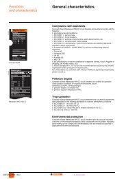
Environmental characteristics<br />
Product certifications<br />
cULus<br />
Temperature Operation °C 0…+ 55<br />
Storage °C - 25…+ 70<br />
Degree of protection <strong>IP</strong> <strong>67</strong><br />
Altitude m 0…2000<br />
Vibration resistance Con<strong>for</strong>ming to IEC 68 part 2-6 15 gn<br />
Shock resistance Con<strong>for</strong>ming to IEC 68-2-27,<br />
test Ea<br />
50 gn, <strong>for</strong> 11 ms<br />
Resistance to electrostatic<br />
discharge<br />
Con<strong>for</strong>ming to IEC 61000-4-2 kV Contact: ± 4<br />
Air: ± 8<br />
Resistance to radiated fields Con<strong>for</strong>ming to IEC 61000-4-3 V/m 10<br />
Immunity to fast transient<br />
currents<br />
Con<strong>for</strong>ming to IEC 61000-4-4 kV Power supply: ± 2<br />
Signal: ± 2<br />
Surge withstand Con<strong>for</strong>ming to IEC 61000-4-5 V Power supply: (symmetrical and asymmetrical) ± 500<br />
Signals: (symmetrical and asymmetrical) ± 1000<br />
Earth/PE: ± 500<br />
Immunity to conducted Con<strong>for</strong>ming to IEC 61000-4-6 V/m 10<br />
disturbance<br />
Resistance to magnetic Con<strong>for</strong>ming to IEC 61000-4-8 A/m 30<br />
fields, 50 Hz<br />
Mounting<br />
All positions<br />
Mechanical fixing<br />
Fixing by two M4 screws (tightening torque 1.5 Nm)<br />
Bus module characteristics<br />
Bus module type FTM 1CN10 FTM 1DN10 FTM 1DP10<br />
Bus type CANopen DeviceNet Profibus-DP<br />
Operating voltage c V 24<br />
Maximum supply current A 9<br />
Binary rate 125, 250 and 500 K bits/s 12 M bits/s<br />
Internal consumption of bus module mA 70 80<br />
Fieldbus characteristics<br />
Bus type CANopen DeviceNet Profibus-DP<br />
Structure Type EN 50325<br />
ISO 11898<br />
EN 50325<br />
ISO 11898<br />
CAN, layer 7 DeviceNet<br />
DIN 19245<br />
EN 50170<br />
Access method<br />
Multimaster, priority<br />
in<strong>for</strong>mation<br />
Master-Slave<br />
Master-Slave,<br />
Multi-Master<br />
Transmission Binary rate 1 M bits/s 500 K bits/s 12 M bits/s<br />
Medium 2 twisted, shielded wires 4 twisted, shielded wires 2 twisted, type A, shielded<br />
wires (RS 485)<br />
Configuration Maximum number of devices 127 63 32 without repeater<br />
126 with repeaters<br />
Maximum length of bus<br />
At 1 M bits/s:<br />
- Max. tap-off length: 0.3 m<br />
- Max. cumulative tap-off<br />
length: 1.5 m<br />
At 500 K bits/s:<br />
- Max. tap-off length: 6 m<br />
- Max. cumulative tap-off<br />
length: 30 m<br />
Main line:<br />
- 500 m without repeater,<br />
- 3 km with repeater<br />
Tap-off:<br />
6 m max.<br />
Without repeater:<br />
At 12 M bits/s:<br />
- 100 m max.<br />
At 1.5 M bits/s:<br />
- 200 m max.<br />
At 500 K bits/s:<br />
- 400 m max.<br />
At < 93.75 K bits/s:<br />
- 1.2 km max.<br />
Presentation, functions:<br />
pages 14501/2 to 14501/8<br />
Description:<br />
page 14501/9<br />
Connections:<br />
pages 14501/10 and 14501/11<br />
References:<br />
pages 14501/14 and 14501/15<br />
Dimensions, schemes:<br />
pages 14501/16 and 14501/17<br />
14501-EN_Ver2.0.fm/12
Characteristics (continued) 5<br />
<strong>IP</strong><br />
<strong>67</strong> <strong>modular</strong> I/O <strong>splitter</strong> <strong>boxes</strong><br />
<strong>for</strong> <strong>fieldbuses</strong> 5<br />
Advantys, FTM <strong>splitter</strong> <strong>boxes</strong><br />
Digital input/output <strong>splitter</strong> box characteristics<br />
Splitter box type Inputs Inputs/outputs<br />
Compact FTM 1DE08Cpp FTM 1DE16C12 FTM 1DD08Cpp FTM 1DD16C12<br />
Expandable FTM 1DE08CppE FTM 1DE16C12E FTM 1DD08CppE FTM 1DD16C12E<br />
Number of inputs/outputs 8I 16 I 8I/O 16 I/O<br />
Internal consumption of <strong>splitter</strong> box mA 30 (M8)<br />
50 (M12)<br />
50 30 (M8)<br />
50 (M12)<br />
Operating voltage c V 24<br />
Splitter box max. supply current A 4<br />
Auxiliary supply max. current A – 4 (only<br />
FTM 1DD16C12)<br />
Bus and I/O undervoltage detection V
References 5<br />
<strong>IP</strong><br />
<strong>67</strong> <strong>modular</strong> I/O <strong>splitter</strong> <strong>boxes</strong><br />
<strong>for</strong> <strong>fieldbuses</strong> 5<br />
Advantys, FTM <strong>splitter</strong> <strong>boxes</strong><br />
108739<br />
Bus modules <strong>for</strong> <strong>modular</strong> <strong>splitter</strong> <strong>boxes</strong><br />
Bus type Maximum number<br />
of <strong>splitter</strong> <strong>boxes</strong><br />
Connection<br />
to bus by<br />
Reference<br />
Weight<br />
kg<br />
CANopen 16 M12 connectors FTM 1CN10 0.420<br />
DeviceNet 16 M12 connectors FTM 1DN10 0.420<br />
108745<br />
108768<br />
108741<br />
FTM 1CN<br />
FTM 1Dp08C08<br />
FTM 1Dp08C12<br />
FTM 1Ap04C12p<br />
FTM 1DD16C12<br />
109017<br />
109018<br />
FTM 1Dp08C08E<br />
FTM 1Dp08C12E<br />
Profibus-DP 16 M12 connectors FTM 1DP10 0.420<br />
Modular digital I/O <strong>splitter</strong> <strong>boxes</strong> <strong>for</strong> all bus types<br />
Number<br />
of I/O<br />
Connection<br />
by<br />
Type Reference Weight<br />
Number,<br />
type of<br />
inputs<br />
8 8,<br />
c 24 V<br />
IEC type 2<br />
0...8,<br />
c 24 V<br />
IEC type 2<br />
16 16,<br />
c 24 V<br />
IEC type 2<br />
0...16,<br />
c 24 V<br />
IEC type 2<br />
Number,<br />
type of<br />
outputs<br />
– 8 x M8 female<br />
connectors<br />
0...8,<br />
transistor<br />
c 24 V/<br />
0.5 A<br />
4 x M12 female<br />
connectors<br />
8 x M8 female<br />
connectors<br />
4 x M12 female<br />
connectors<br />
– 8 x M12 female<br />
connectors<br />
0...16, 8 x M12 female<br />
transistor connectors<br />
c 24 V/<br />
0.5 A<br />
Modular analogue I/O <strong>splitter</strong> <strong>boxes</strong> <strong>for</strong> all bus types<br />
4 4,<br />
0...20 mA<br />
4...20 mA<br />
4,<br />
c ± 10 V<br />
c 0...10 V<br />
– 4,<br />
0...20 mA<br />
4...20 mA<br />
– 4 x M12 female<br />
connectors<br />
– 4 x M12 female<br />
connectors<br />
4 x M12 female<br />
connectors<br />
kg<br />
Compact FTM 1DE08C08 0.120<br />
Expandable FTM 1DE08C08E 0.120<br />
Compact FTM 1DE08C12 0.120<br />
Expandable FTM 1DE08C12E 0.120<br />
Compact FTM 1DD08C08 0.120<br />
Expandable FTM 1DD08C08E 0.120<br />
Compact FTM 1DD08C12 0.120<br />
Expandable FTM 1DD08C12E 0.120<br />
Compact FTM 1DE16C12 0.220<br />
Expandable FTM 1DE16C12E 0.220<br />
Compact FTM 1DD16C12 0.220<br />
Expandable FTM 1DD16C12E 0.220<br />
Compact FTM 1AE04C12C 0.130<br />
Compact FTM 1AE04C12T 0.130<br />
Compact FTM 1AS04C12C 0.130<br />
4, 4 x M12 female Compact FTM 1AS04C12T 0.130<br />
c ±10 V<br />
c 0...10 V<br />
connectors<br />
Connection accessories<br />
Description Composition Length<br />
m<br />
For CANopen/DeviceNet buses<br />
Bus connection cables Fitted with 2 elbowed M12,<br />
5-pin connectors,<br />
Connectors<br />
M12<br />
Line terminator<br />
(<strong>for</strong> end of bus)<br />
For Profibus-DP bus<br />
Reference<br />
Weight<br />
kg<br />
0.3 FTX CN3203 0.040<br />
0.6 FTX CN3206 0.070<br />
A encoded, one at each end<br />
1 FTX CN3210 0.100<br />
2 FTX CN3220 0.160<br />
3 FTX CN3230 0.220<br />
5 FTX CN3250 0.430<br />
5-pin, male, A encoded – FTX CN12M5 0.050<br />
5-pin, female, A encoded – FTX CN12F5 0.050<br />
Fitted with one M12 – FTX CNTL12 0.010<br />
connector<br />
Bus connection cables Fitted with 2 straight M12,<br />
5-pin connectors, one at<br />
each end<br />
Fitted with 2 elbowed M12,<br />
5-pin connectors, one at<br />
each end<br />
0.3 FTX DP1203 0.040<br />
0.6 FTX DP1206 0.070<br />
1 FTX DP1210 0.100<br />
2 FTX DP1220 0.160<br />
3 FTX DP1230 0.220<br />
5 FTX DP1250 0.430<br />
0.3 FTX DP3203 0.040<br />
0.6 FTX DP3206 0.070<br />
1 FTX DP3210 0.100<br />
2 FTX DP3220 0.160<br />
3 FTX DP3230 0.220<br />
5 FTX DP3250 0.430<br />
Presentation, functions:<br />
pages 14501/2 to 14501/8<br />
Description:<br />
page 14501/9<br />
Connections:<br />
pages 14501/10 and 14501/11<br />
Characteristics:<br />
pages 14501/12 and 14501/13<br />
Dimensions, schemes:<br />
pages 14501/16 and 14501/17<br />
14501-EN_Ver2.0.fm/14
References (continued) 5<br />
<strong>IP</strong><br />
<strong>67</strong> <strong>modular</strong> I/O <strong>splitter</strong> <strong>boxes</strong><br />
<strong>for</strong> <strong>fieldbuses</strong> 5<br />
Advantys, FTM <strong>splitter</strong> <strong>boxes</strong><br />
108768<br />
FTX CY1208<br />
Connection accessories (continued)<br />
Description Composition Length<br />
m<br />
For Profibus-DP bus (continued)<br />
Connectors<br />
M12 male, 5-pin,<br />
B encoded<br />
M12 female, 5-pin,<br />
B encoded<br />
Line terminator<br />
(<strong>for</strong> end of bus)<br />
For all bus types<br />
c 24 V bus module power<br />
supply connection cables<br />
T-connector<br />
<strong>for</strong> power supply cable<br />
For internal bus<br />
Internal bus connection<br />
cables<br />
<strong>for</strong> bus module <strong>splitter</strong> box<br />
linking<br />
Auxiliary c 24 V power<br />
supply connection cables<br />
<strong>for</strong> bus module <strong>splitter</strong> box<br />
linking<br />
Auxiliary c 24 V power<br />
supply connection cables<br />
Line terminator<br />
<strong>for</strong> end of internal bus<br />
Separate components<br />
Fitted with one M12<br />
connector<br />
Reference<br />
Weight<br />
kg<br />
– FTX DP12M5 0.050<br />
– FTX DP12F5 0.050<br />
– FTX DPTL12 0.010<br />
Fitted with two 7/8, 5-pin 0.6 FTX DP2206 0.150<br />
connectors, one at each 1 FTX DP2210 0.190<br />
end<br />
2 FTX DP2220 0.310<br />
5 FTX DP2250 0.750<br />
Fitted with one 7/8, 5-pin<br />
connector, other end<br />
free<br />
Fitted with two 7/8, 5-pin<br />
connectors<br />
Fitted with 2 elbowed<br />
M12, 6-pin connectors,<br />
one at each end<br />
Fitted with 2 elbowed<br />
M12, 6-pin connectors,<br />
one at each end<br />
Fitted with 1 elbowed<br />
M12, 6-pin connector,<br />
other end free<br />
Fitted with one M12<br />
connector<br />
1.5 FTX DP2115 0.240<br />
3 FTX DP2130 0.430<br />
5 FTX DP2150 0.700<br />
– FTX CNCT1 0.100<br />
0.3 FTX CB3203 0.060<br />
0.6 FTX CB3206 0.090<br />
1 FTX CB3210 0.120<br />
2 FTX CB3220 0.215<br />
3 FTX CB3230 0.310<br />
5 FTX CB3250 0.500<br />
0.3 FTX CA3203 0.035<br />
0.6 FTX CA3206 0.045<br />
1 FTX CA3210 0.060<br />
2 FTX CA3220 0.090<br />
3 FTX CA3230 0.120<br />
5 FTX CA3250 0.180<br />
0.3 FTX CA3103 0.030<br />
0.6 FTX CA3106 0.035<br />
1 FTX CA3110 0.040<br />
2 FTX CA3120 0.070<br />
3 FTX CA3130 0.100<br />
5 FTX CA3150 0.160<br />
– FTX CBTL12 0.030<br />
Description Composition Reference Weight<br />
kg<br />
Connectors 7/8 male, 5-pin FTX C78M5 0.050<br />
7/8 female, 5-pin FTX C78F5 0.050<br />
Sealing plugs For M8 connector (lot of 10) FTX CM08B 0.100<br />
For M12 connector (lot of 10) FTX CM12B 0.100<br />
Y-connectors<br />
Connection of 2 x M8 connectors FTX CY1208 0.020<br />
to M12 connector on <strong>splitter</strong> box<br />
Connection of 2 x M12 connectors FTX CY1212 0.030<br />
to M12 connector on <strong>splitter</strong> box<br />
Diagnostics adaptor Fitted with two M12 connectors FTX DG12 0.020<br />
Marker labels Lot of 10 FTX MLA10 0.010<br />
CD-ROM<br />
Configuration files, technical<br />
manuals and operating instructions<br />
FTX ES00 0.050<br />
Presentation, functions:<br />
pages 14501/2 to 14501/8<br />
Description:<br />
page 14501/9<br />
Connections:<br />
pages 14501/10 and 14501/11<br />
Characteristics:<br />
pages 14501/12 and 14501/13<br />
Dimensions, schemes:<br />
pages 14501/16 and 14501/17<br />
14501-EN_Ver2.0.fm/15
Dimensions 5<br />
<strong>IP</strong><br />
<strong>67</strong> <strong>modular</strong> I/O <strong>splitter</strong> <strong>boxes</strong><br />
<strong>for</strong> <strong>fieldbuses</strong> 5<br />
Advantys, FTM <strong>splitter</strong> <strong>boxes</strong><br />
Bus modules<br />
FTM 1pp10<br />
34,5<br />
5<br />
20,5<br />
125,3<br />
151<br />
22<br />
50,3<br />
50<br />
Splitter <strong>boxes</strong><br />
Common side view FTM 1DD16C12 FTM 1DD16C12E<br />
FTM 1DE16C12E<br />
34,5<br />
3 33 3<br />
73<br />
3 33 3<br />
73<br />
FTM 1DE16C12<br />
3 33 3<br />
73<br />
FTM 1Dp08C12<br />
FTM 1Ap04C12p<br />
4<br />
2<br />
75 5<br />
2<br />
2<br />
126<br />
126<br />
126<br />
126<br />
22<br />
50<br />
50<br />
50<br />
30<br />
FTM 1Dp08C08 FTM 1Dp08C12E FTM 1Dp08C08E<br />
34,5<br />
4<br />
34,5<br />
4<br />
34,5<br />
4<br />
151<br />
75 5<br />
75 5<br />
75 5<br />
151<br />
126<br />
22<br />
30<br />
22<br />
30<br />
22<br />
30<br />
Y-connectors<br />
FTX CY1208<br />
FTX CY1212<br />
45<br />
45<br />
15 33<br />
15 35<br />
Presentation, functions:<br />
pages 14501/2 to 14501/8<br />
Description:<br />
page 14501/9<br />
Connections:<br />
pages 14501/10 and 14501/11<br />
Characteristics:<br />
pages 14501/12 and 14501/13<br />
References:<br />
pages 14501/16 and 14501/17<br />
14501-EN_Ver2.0.fm/16
Schemes 5<br />
<strong>IP</strong><br />
<strong>67</strong> <strong>modular</strong> I/O <strong>splitter</strong> <strong>boxes</strong><br />
<strong>for</strong> <strong>fieldbuses</strong> 5<br />
Advantys, FTM <strong>splitter</strong> <strong>boxes</strong><br />
Splitter box connection<br />
Input/output connection <strong>for</strong> digital <strong>splitter</strong> <strong>boxes</strong><br />
1 2<br />
24 V S2<br />
5<br />
S1<br />
0 V<br />
4<br />
3<br />
0 V 3 4 S<br />
+ 24 V<br />
1<br />
Input/output connection <strong>for</strong> analogue <strong>splitter</strong> <strong>boxes</strong><br />
Analogue input<br />
Analogue output<br />
1 2<br />
1<br />
24 V<br />
Analogue<br />
24 V<br />
input + signal<br />
Analogue<br />
5<br />
0 V<br />
input – signal<br />
4 3<br />
M12 female connector<br />
Analogue<br />
5<br />
output signal<br />
4 3<br />
M12 female connector<br />
2<br />
0 V<br />
M12 female connector<br />
Auxiliary power supply<br />
+ 24 V (2)<br />
1<br />
6<br />
M8 female connector<br />
0 V<br />
Bus input/Internal bus output of <strong>splitter</strong> <strong>boxes</strong><br />
Internal bus input<br />
Internal bus output<br />
Internal bus<br />
0 V<br />
+ 24 V (2)<br />
Internal bus<br />
4<br />
3 0 V<br />
6<br />
+ 24 V (1)<br />
M12 male connector<br />
(1) Supply to <strong>splitter</strong> box and sensors.<br />
(2) Supply to actuators.<br />
Bus module connection on CANopen and DeviceNet bus<br />
Supply to bus module Bus input/Bus outputs of bus module<br />
Supply input Bus input Bus output Internal bus output<br />
24 V (1)<br />
4<br />
24 V (2)<br />
5<br />
3<br />
2<br />
1<br />
0 V<br />
0 V<br />
CAN-H 4 3<br />
5<br />
1<br />
2<br />
CAN-L<br />
0 V<br />
24 V<br />
5<br />
1 2<br />
M12 male connector<br />
CAN-L<br />
0 V<br />
24 V<br />
3<br />
5<br />
4<br />
2 1<br />
CAN-H<br />
Internal bus<br />
0 V 3 4 6<br />
+ 24 V (1)<br />
2<br />
M12 female connector<br />
Internal bus<br />
0 V 3 4 6<br />
+ 24 V (1)<br />
2<br />
5<br />
1<br />
5<br />
1<br />
Internal bus<br />
0 V<br />
+ 24 V (2)<br />
Internal bus<br />
0 V<br />
+ 24 V (2)<br />
7/8 male connector<br />
M12 male connector<br />
M12 female connector<br />
M12 female connector<br />
(1) Supply to <strong>splitter</strong> box and sensors.<br />
(2) Supply to actuators.<br />
Bus module connection on Profibus-DP bus<br />
Supply to bus module Bus input/Bus outputs of bus module<br />
Supply input Bus input Bus output Internal bus output<br />
24 V (1)<br />
4<br />
24 V (2)<br />
5<br />
3<br />
2<br />
1<br />
0 V<br />
0 V<br />
Cable B<br />
(red)<br />
5 V<br />
0 V<br />
4 3<br />
5<br />
Cable A<br />
(green)<br />
1 2<br />
0 V<br />
Cable B (red)<br />
3 4<br />
5<br />
Cable A (green)<br />
5 V<br />
2 1<br />
Internal bus<br />
0 V 3 4 6<br />
+ 24 V (1)<br />
2<br />
5<br />
1<br />
Internal bus<br />
0 V<br />
+ 24 V (2)<br />
7/8 male connector M12 male connector<br />
M12 female connector<br />
M12 female connector<br />
(1) Supply to <strong>splitter</strong> box and sensors.<br />
(2) Supply to actuators.<br />
Y-connector connection<br />
FTX CY1208<br />
M8<br />
female<br />
1<br />
3<br />
4<br />
M8<br />
female<br />
1<br />
3<br />
4<br />
Note: connectors linked to shielding.<br />
FTX CY1212<br />
M12<br />
female<br />
1<br />
2<br />
3<br />
4<br />
5<br />
M12<br />
female<br />
1<br />
2<br />
3<br />
4<br />
5<br />
1 2 3 4<br />
M12 male<br />
1 2 3 4 5<br />
M12 male<br />
Presentation, functions:<br />
pages 14501/2 to 14501/8<br />
Description:<br />
page 14501/9<br />
Connections:<br />
pages 14501/10 and 14501/11<br />
Characteristics:<br />
pages 14501/12 and 14501/13<br />
References:<br />
pages 14501/16 and 14501/17<br />
14501-EN_Ver2.0.fm/17