Electromechanical pressure switches 0
Electromechanical pressure switches 0
Electromechanical pressure switches 0

You also want an ePaper? Increase the reach of your titles
YUMPU automatically turns print PDFs into web optimized ePapers that Google loves.
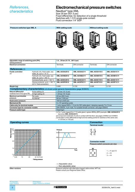
References,characteristics<strong>Electromechanical</strong> <strong>pressure</strong> <strong>switches</strong> 0Nautilus ® type XMLSize 35 bar (507.5 psi)Adjustable differential, for regulation between 2 thresholdsSwitches with 2 C/O single-pole contactsFluid connection 1/4” BSPPressure <strong>switches</strong> type XML CWith setting scaleAdjustable range of switching point (PH)(Rising <strong>pressure</strong>)Electrical connection3.5…35 bar (50.75…507.5 psi)TerminalsReferences (1)Fluids controlled(2)Hydraulic oils, fresh water, seawater, air, up to + 160 °CXML C035B2S12Corrosive fl uids, up to + 160 °C XML C035C2S12Weight (kg) 0.695Complementary characteristics not shown under general characteristics (page 30350/3)Possible differentialMin. at low setting (3)(subtract from PH to give PB) Min. at high setting (4)Max. at high settingMaximum permissible Per cycle<strong>pressure</strong>AccidentalDestruction <strong>pressure</strong>Mechanical lifeCable entry for terminal modelsPressure switch typeOperating curves1 bar (14.5 psi)1.5 bar (21.75 psi)22 bar (319 psi)45 bar (652.5 psi)80 bar (1160 psi)160 bar (2320 psi)5 x 10 6 operating cycles1 entry tapped M20 x 1.5 mm for ISO cable gland, clamping capacity 7 to 13 mmDiaphragm(1) For 1 entry tapped for n° 13 cable gland, replace S12 by S11 (example: XML C035B2S12becomes XML C035B2S11).(2) Component materials of units in contact with the fl uid, see pages 30369/2 and 30369/3.(3) Deviation of the differential at low setting point for <strong>switches</strong> of the same size:± 0.2 bar (± 2.9 psi).(4) Deviation of the differential at high setting point for <strong>switches</strong> of the same size:± 0.5 bar (± 7.25 psi).ConnectionTerminal modelRising <strong>pressure</strong>bar35301PressurePH131412 11232422 21202PB10Time3,502,5 10 13 20 33,5barFalling <strong>pressure</strong>1 Maximum differential2 Minimum differentialOther versions–– Adjustable valuePressure <strong>switches</strong> with alternative tapped cable entries: NPT etc.Please consult your Regional Sales Offi ce.Accessories:page 30364/2Dimensions:pages 30364/3 to 30364/5430359-EN_Ver6.0.indd
References,characteristics<strong>Electromechanical</strong> <strong>pressure</strong> <strong>switches</strong> 0Nautilus ® type XMLSize 35 bar (507.5 psi)Dual stage, fi xed differential, for detection at each thresholdSwitches with 2 C/O single-pole contacts (one per stage)Fluid connection 1/4” BSPPressure <strong>switches</strong> type XML DWithout setting scaleAdjustable range of each 2nd stage switching point (PH2)switching point1st stage switching point (PH1)(Rising <strong>pressure</strong>)Spread between 2 stages (PH2 - PH1)Electrical connection4.4…35 bar (63.8…507.5 psi)1.9…32.5 bar (27.55…471.25 psi)2.5…20.4 bar (36.25…295.8 psi)TerminalsReferences (1)Fluids controlled(2)Hydraulic oils, fresh water, seawater, air, up to + 160 °CXML D035B1S12Corrosive fl uids, up to + 160 °C XML D035C1S12Weight (kg) 0.715Complementary characteristics not shown under general characteristics (page 30350/3)Natural differential(subtract from PH1/PH2to give PB1/PB2)Maximum permissible<strong>pressure</strong>At low setting (3)At high setting (4)Per cycleAccidentalDestruction <strong>pressure</strong>Mechanical lifeCable entry for terminal modelsPressure switch type1.5 bar (21.75 psi)2.6 bar (37.7 psi)45 bar (652.5 psi)80 bar (1160 psi)160 bar (2320 psi)5 x 10 6 operating cycles1 entry tapped M20 x 1.5 mm for ISO cable gland, clamping capacity 7 to 13 mmDiaphragm(1) For 1 entry tapped for n° 13 cable gland, replace S12 by S11 (example: XML D035B1S12becomes XML D035B1S11).(2) Component materials of units in contact with the fl uid, see pages 30369/2 and 30369/3.(3) Deviation of the differential at low setting point for <strong>switches</strong> of the same size:± 0.3 bar (± 4.35 psi).(4) Deviation of the differential at high setting point for <strong>switches</strong> of the same size:± 0.7 bar (± 10.15 psi).Operating curvesHigh setting tripping points of contacts 1 and 2 Natural differential of contacts 1 and 2PH2 setting (rising <strong>pressure</strong>)bar353022,320104,41201,9 10 14,6 20 3032,5barPH1 setting (rising <strong>pressure</strong>)1 Maximum differential2 Minimum differentialRising <strong>pressure</strong>bar3532,53020104,4G1,90E0,4 2,9 10 20 29,9 32,4barEF Contact 1 (stage 1)GH Contact 2 (stage 2)FHFalling <strong>pressure</strong>PressurePH2PB2PH1PB1Time–– Adjustable value--- Non adjustable valueConnectionTerminal modelContact 2 Contact 1(stage 2) (stage 1)131412 11232422 21Other versionsPressure <strong>switches</strong> with alternative tapped cable entries: NPT etc.Please consult your Regional Sales Offi ce.30359-EN_Ver6.0.indd5