Operator dialogue terminals - Trinet
Operator dialogue terminals - Trinet
Operator dialogue terminals - Trinet

Create successful ePaper yourself
Turn your PDF publications into a flip-book with our unique Google optimized e-Paper software.
Catalogue<br />
June<br />
Automation and control<br />
Human/Machine interfaces
Art. 61231 - DIA6ED2030901EN<br />
Art. 67341 - MKTED203111EN<br />
Safety solutions<br />
using Preventa<br />
2003<br />
Ethernet TCP/IP<br />
Transparent Factory<br />
Art. 55053 - MKTED203041EN<br />
2004<br />
AS-Interface<br />
cabling system<br />
2003<br />
Human/Machine <strong>dialogue</strong><br />
Communication<br />
Control and Protection,<br />
Detection,<br />
Data-processing,<br />
Human/Machine <strong>dialogue</strong><br />
Control and Protection,<br />
Detection,<br />
Data-processing,<br />
Human/Machine <strong>dialogue</strong>,<br />
Communication<br />
Control and signalling units<br />
Art. 28697 - MKTED299014EN<br />
The<br />
Essential guide<br />
2001<br />
Telemecanique<br />
Components for<br />
Human-Machine interfaces<br />
Terminals and display units<br />
Art. 96949 - MKTED2040401EN<br />
Automation and control<br />
Human/Machine interfaces<br />
To be issued: 2nd quarter 2004<br />
2004<br />
To be issued<br />
Automation and control<br />
Mounting systems<br />
Art. 70263 - MKTED203113EN<br />
2004<br />
Automation and control<br />
Interfaces, I/O splitter boxes<br />
and power supplies<br />
2003<br />
2003<br />
Art. 70455 - MKTED204011EN<br />
Automation and control<br />
Automation and relay functions<br />
Human/Machine <strong>dialogue</strong><br />
Supervision<br />
Panel-building and cabling accessories
AUTC201108140EN<br />
Distributed I/O<br />
Advantys STB<br />
AUTC201104124EN<br />
2003 Modicon Momentum<br />
automation platform<br />
2002<br />
AUTC201384126EN<br />
Automation platform<br />
Modicon Quantum<br />
Art. 70986 - MKTED204013EN<br />
2003<br />
Automation platform<br />
Modicon Premium<br />
and PL7 software<br />
Art. 70984 - MKTED204012EN<br />
2004 Automation platform<br />
Modicon TSX Micro<br />
and PL7 software<br />
2004<br />
An overview<br />
of the product range<br />
- Control and protection,<br />
- Detection,<br />
Data-processing,<br />
Communication<br />
- Data-processing,<br />
- Human/Machine <strong>dialogue</strong>,<br />
- Communication,<br />
- Supervision,<br />
- Panel-building and cabling accessories,<br />
- Power distribution<br />
Art. 61233 - DIA7ED2030902EN<br />
Art. 66692 - DIA7ED20310006EN<br />
2004<br />
Twin Line<br />
Motion control<br />
Motion control<br />
Lexium<br />
Art. 46753 - MKTED203011EN<br />
2003<br />
Soft starters and<br />
variable speed drives<br />
Art. 27501 - MKTED201001EN<br />
2003<br />
Art. 54752 - MKTED203031EN<br />
2003<br />
Global Detection<br />
Electronic and<br />
electromechanical sensors<br />
2001<br />
Motor starter solutions<br />
Control and protection<br />
components<br />
Control and protection<br />
Detection
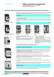
tico 732<br />
E 5 3 1<br />
6 4 2<br />
R<br />
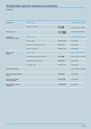
Automation solutions<br />
An overview of the product range<br />
Products listed in this catalogue<br />
Product listed in other catalogues (see previous pages)<br />
Control and<br />
protection<br />
Contactors<br />
from6to16A<br />
Contactors Contactors<br />
from9to150A from 185 to 800 A<br />
Modular contactors<br />
Circuit-breakers<br />
Rotary switch disconnector<br />
Thermal overload relays Measurement and<br />
Motor starters open version Contactor and reversing<br />
control relays<br />
contactor breakers<br />
Direct on-line starters,<br />
enclosed version<br />
Star-delta starters,<br />
enclosed version<br />
Control and<br />
protection<br />
Soft starters open and<br />
enclosed version<br />
Soft start-soft stop units<br />
for asynchronous motors<br />
Variable speed drives for asynchronous motors<br />
Ready-assembled<br />
variable speed drives<br />
Power supplies and transformers<br />
Detection<br />
Photo-electric<br />
detectors<br />
Inductive, capacitive, magnet and ultrasonic<br />
proximity sensors<br />
Limit switches<br />
Limit switches for safety<br />
applications<br />
Electromechanical pressure<br />
and vacuum switches<br />
Electronic pressure<br />
and vacuum switches<br />
Connectors<br />
Encoders<br />
Inductive identification system<br />
Data processing<br />
Twido programmable<br />
controllers<br />
Nano programmable<br />
controllers<br />
Micro<br />
automation platform<br />
Premium<br />
automation platform<br />
Quantum<br />
automation platform<br />
Momentum<br />
automation platform<br />
TBX distributed I/O<br />
Advantys STB<br />
distributed I/O<br />
IP 67 splitter boxes<br />
Telefast ® 2 pre-wired<br />
system<br />
Interfaces<br />
Control<br />
relays<br />
Electronic<br />
timing relays<br />
Zelio Logic<br />
smart relays<br />
Preventa safety<br />
modules<br />
Human-Machine<br />
<strong>dialogue</strong><br />
Control and signalling units<br />
Cam switches<br />
Control stations<br />
Pendant control stations<br />
Magelis operator <strong>dialogue</strong> <strong>terminals</strong><br />
Illuminated beacons<br />
and indicator banks<br />
Totalising timers<br />
and counters<br />
Foot switches<br />
Emergency stop<br />
stations<br />
Emergency stop<br />
trip wire switches<br />
Communication<br />
Modbus TCP/X-Way communication architecture: TCP/IP Ethernet network, Modbus Plus network, Fipway network, Jnet network,<br />
AS-Interfaces cabling system, Fipio bus, CANopen bus, Uni-Telway bus, Modbus bus, INTERBUS, Profibus DP, asynchronous serial links<br />
FactoryCast<br />
Web solutions<br />
FactoryCast HMI<br />
Web solutions<br />
Web and Internet technologies<br />
Supervision<br />
Magelis iPC industrial PC<br />
Vijeo Look<br />
supervisory software<br />
Monitor Pro<br />
supervisory software<br />
Panel building<br />
and cabling<br />
accessories<br />
Wall-mounted enclosures<br />
Floor-standing enclosures<br />
Uprights, mounting plates, mounting rail,<br />
cable ducting and cable clips<br />
Prefabricated busbar systems and<br />
power distribution systems<br />
Tego Dial<br />
Tego Power<br />
Profil front panel<br />
Terminal blocks Cable ends Marking accessories<br />
Tools<br />
Power<br />
distribution<br />
Prefadis service poles and posts,<br />
lighting poles<br />
Canalis busbar trunking for lighting distribution<br />
Canalis busbar trunking for low and medium power distribution<br />
Canalis busbar trunking for high power distribution<br />
Mobile distribution: Canalis track section and cable carriers<br />
Services<br />
Product reference index<br />
Technical information<br />
Schneider Electric worldwide
General contents 0<br />
Human/Machine interfaces<br />
1 – <strong>Operator</strong> <strong>dialogue</strong> <strong>terminals</strong><br />
Selection guide .............................................page1/2<br />
Magelis display units and <strong>terminals</strong><br />
Magelis compact display units .............................. page1/10<br />
Magelis display units with alphanumeric screen ................. page1/14<br />
Magelis display units and <strong>terminals</strong> with matrix screen ........... page1/16<br />
Magelis <strong>terminals</strong> with alphanumeric screen ................... page1/18<br />
Magelis graphic <strong>terminals</strong><br />
Magelis 5" <strong>terminals</strong> with keypad or touch-sensitive screen. ....... page1/26<br />
Magelis 5" and 10" <strong>terminals</strong> with touch-sensitive screen and keys . . page 1/28<br />
Magelis 10" <strong>terminals</strong> with keypad or touch-sensitive screen. . . . . . . page 1/30<br />
New Technology Magelis touch-sensitive <strong>terminals</strong> ............. page1/36<br />
2 – Magelis iPC industrial PLCs<br />
Selection guide .............................................page2/2<br />
“All in one” compact products<br />
Magelis Smart iPC range ................................... page2/9<br />
Magelis Compact iPC range ................................. page2/9<br />
Modular products<br />
Magelis Modular iPC range ................................ page2/15<br />
3 – Softwares and Web servers<br />
Selection guide .............................................page3/2<br />
Traditional architecture, HMI executed on dedicated terminal or PC platform<br />
XBT L1003 development software ............................ page3/4<br />
Vijeo Designer configuration software ......................... page3/8<br />
Vijeo Look supervisory software ............................. page3/10<br />
Monitor Pro V7.2 supervisory software ........................ page3/24<br />
OFS data server software. ................................. page3/38<br />
Web architecture, embedded HMI in PLC<br />
Standard Web services. ................................... page3/44<br />
FactoryCast Web server ................................... page3/46<br />
FactoryCast HMI Web server ............................... page3/48<br />
4 – Services<br />
Technical information<br />
Automation product certifications ............................. page4/2<br />
Schneider Electric worldwide<br />
Addresses ............................................... page4/4<br />
Index<br />
Product reference index ................................... page4/10<br />
5
1/0
Contents 0<br />
1-<strong>Operator</strong> <strong>dialogue</strong> <strong>terminals</strong><br />
Selectionguide.............................................page1/2<br />
Magelis display units and <strong>terminals</strong><br />
b Magelis compact display units. ............................... page1/11<br />
1<br />
b Magelis display units<br />
v with 2-line alphanumeric screen ............................ page1/15<br />
b Magelis display units and <strong>terminals</strong><br />
v with 8-line matrix screen .................................. page1/17<br />
b Magelis <strong>terminals</strong><br />
v with 2-line alphanumeric screen ............................ page1/19<br />
v with 2 or 4-line alphanumeric screen ......................... page1/21<br />
Magelis graphic <strong>terminals</strong><br />
b Magelis 5" graphic <strong>terminals</strong><br />
v with keypad or touch-sensitive screen. ....................... page1/27<br />
b Magelis 5" or 10" graphic <strong>terminals</strong><br />
v with touch-sensitive screen and keys ........................ page1/29<br />
b Magelis 10" graphic <strong>terminals</strong><br />
v with keypad or touch-sensitive screen. ....................... page1/31<br />
b New Technology Magelis touch-sensitive graphic <strong>terminals</strong><br />
v with 5" screen .......................................... page1/37<br />
v with 7", 10" or 12" screen. ................................. page1/39<br />
b Separate parts for operator <strong>dialogue</strong> <strong>terminals</strong> ................... page1/40<br />
b ConnectiontoFipiobus/Fipwaynetwork........................ page 1/43<br />
b Connection to Modbus Plus network. .......................... page1/45<br />
1/1
Selection guide 1<br />
<strong>Operator</strong><br />
<strong>dialogue</strong> <strong>terminals</strong> 1<br />
Magelis display units and <strong>terminals</strong><br />
Applications Display of text messages Display of text messages<br />
and/or semi-graphics<br />
Type of unit Compact display units Display units<br />
Display Type Back-lit green LCD,<br />
height 5.5 mm<br />
or<br />
Back-lit green, orange or<br />
red LCD,<br />
height 4.34…17.36 mm<br />
Fluorescent green matrix<br />
(5 x 7 pixels),<br />
height 5 mm<br />
or<br />
Back-litLCD(5x7pixels),<br />
height 9 mm<br />
Back-lit monochrome matrix<br />
LCD (240 x 64 pixels),<br />
height 5.3 or 10.6 mm<br />
Capacity<br />
2 lines of 20 characters or<br />
1to4linesof5to20<br />
characters<br />
2 lines of 20 characters 4 to 8 lines of 20 to 40<br />
characters<br />
Data entry<br />
Via keypad with<br />
8 keys (4 with changeable<br />
legends)<br />
Display only<br />
or<br />
via keypad with 4 function keys + 1 service key<br />
or<br />
5 service keys<br />
Memory capacity Application 512 Kb Flash 128 Kb/256 Kb Flash 384 Kb Flash EPROM<br />
Extension via type II PCMCIA –<br />
Functions Maximum number of pages 128/200 application pages<br />
256 alarm pages<br />
100/200 application pages<br />
128/256 alarm pages<br />
256 print-out form pages (1)<br />
600 application pages<br />
256 alarm pages<br />
256 print-out form pages (1)<br />
Variables per page 40…50 50<br />
Representation of variables Alphanumeric Alphanumeric, bargraph, gauge<br />
Recipes –<br />
Curves –<br />
Alarm logs – Depending on model<br />
Real-time clock<br />
AccesstothePLCreal-timeclock<br />
Alarm relay – No<br />
Communication Asynchronous serial link RS 232 C/RS 485 RS 232 C/RS 485/RS 422<br />
Downloadable protocols Uni-Telway, Modbus Uni-Telway, Modbus, AEG and for PLC brands: Allen Bradley, GE<br />
Fanuc, Omron, Siemens<br />
Bus and networks – AS-Interface using 22.5 pitch module<br />
Printer link – RS 232 C asynchronous serial link (1)<br />
Development software<br />
Operating systems<br />
XBT L1001 and XBT L1003 (under Windows 98, 2000 and XP)<br />
Magelis<br />
Type of terminal XBT N XBT H XBT HM<br />
Pages 1/11 1/15 1/17<br />
(1) Depending on model.<br />
1/2
1<br />
1<br />
Display of text messages<br />
Control and parametering of data<br />
Terminals<br />
Display of text messages and/or semi-graphics<br />
Control and parametering of data<br />
1<br />
Fluorescent green matrix (5 x 7 pixels), height 5 mm<br />
or<br />
Back-lit LCD (5 x 7 pixels), height 9 mm<br />
Fluorescent green matrix (5 x 7 pixels), height 5 mm<br />
or<br />
Back-lit LCD (5 x 7 pixels), height 5 mm<br />
Back-lit monochrome matrix LCD (240 x 64 pixels),<br />
height 5.3 or 10.6 mm<br />
2 lines of 20 characters 2 or 4 lines of 40 characters 4 to 8 lines of 20 to 40 characters<br />
Viakeypadwith<br />
8 function keys + 9 service keys<br />
or<br />
keypad with 12 function keys<br />
+ 10 service keys + 12 numeric keys<br />
Viakeypadwith<br />
24 function keys<br />
+ 10 service keys<br />
+ 12 alphanumeric keys<br />
Via keypad with<br />
12 function keys<br />
10 service keys<br />
12 numeric keys<br />
4 soft function keys<br />
256 Kb Flash EPROM 384 Kb Flash EPROM 512 Kb Flash EPROM<br />
–<br />
400 application pages<br />
256 alarm pages<br />
256 print-out form pages (1)<br />
800 application pages<br />
256 alarm pages<br />
256 print-out form pages (1)<br />
800 application pages<br />
256 alarm pages<br />
256 print-out form pages (1)<br />
50<br />
Alphanumeric<br />
Alphanumeric, bargraph, gauge<br />
–<br />
–<br />
Depending on model<br />
Access to the PLC real-time clock Built-in Access to the PLC real-time clock<br />
No Yes No<br />
RS 232 C/RS 485/RS 422<br />
Uni-Telway, Modbus, AEG and for PLC brands: Allen Bradley, GE Fanuc, Omron, Siemens<br />
AS-Interface using 22.5 pitch module – AS-Interface using 22.5 pitch module<br />
RS 232 C asynchronous serial link (1)<br />
XBT L1001 and XBT L1003 (under Windows 98, 2000 and XP)<br />
Magelis<br />
XBT P XBT E XBT PM<br />
1/19 1/21 1/17<br />
1/3
Selection guide 1<br />
<strong>Operator</strong><br />
<strong>dialogue</strong> <strong>terminals</strong> 1<br />
Magelis graphic <strong>terminals</strong><br />
Applications<br />
Display of text messages and graphic objects<br />
Control and parametering of data<br />
Type of unit<br />
Graphic <strong>terminals</strong><br />
Display Type Back-lit monochrome LCD (320 x 240 pixels)<br />
or Colour LCD STN with touch-sensitive screen (320 x 240 pixels) with optimum viewing angle<br />
(1)<br />
Capacity 5.7"<br />
Data entry<br />
Via touch-sensitive screen<br />
4 tactile feedback keys (XBT-FC)<br />
Via keypad with<br />
10 static function keys<br />
8 soft function keys<br />
12 service keys<br />
12 alphanumeric keys<br />
Memory capacity Application 8MbFlashEPROM(viaPCMCIAtypeIIcard)<br />
Extension<br />
By PCMCIA type II card, 8 or 16 Mb<br />
Functions Maximum number of pages 50 to 720 application, alarm, help and print-out form pages depending on the memory card used<br />
(512 alarms maximum)<br />
Variables per page 64<br />
Representation of variables<br />
Alphanumeric, bitmap, bargraph, gauge, potentiometer, selector<br />
Recipes<br />
125 records maximum with 5000 values maximum<br />
Curves 16<br />
Alarm logs<br />
Yes<br />
Real-time clock<br />
AccesstothePLCreal-timeclock<br />
Alarm relay<br />
Yes<br />
Communication Asynchronous serial link RS 232 C/RS 485/RS 422<br />
Downloadable protocols<br />
Uni-Telway, Modbus, AEG and for PLC brands: Allen Bradley, GE Fanuc, Omron, Siemens<br />
Bus and networks<br />
Printer link<br />
Modbus Plus, Fipio/Fipway with add-on PCMCIA type III card, Ethernet 10/100 TCP/IP<br />
(1) (2)<br />
RS 232 C asynchronous serial link (depending on model)<br />
Development software<br />
Operating systems<br />
Type of terminal<br />
XBT L1003 (under Windows 98, 2000 and XP)<br />
Magelis<br />
XBT F01/F03/FC<br />
Pages 1/27<br />
(1) Depending on model.<br />
(2) TCP/IP with Modbus protocol for XBT F.<br />
(3) Uni-Telway version V2 for Nano/Micro/Premium PLCs.<br />
1/4
1<br />
1<br />
New Technology touch-sensitive graphic <strong>terminals</strong><br />
1<br />
Back-lit monochrome LCD (640 x 480 pixels)<br />
or Back-lit colour LCD TFT (640 x 480 pixels) with optimum viewing angle (1)<br />
9.5" (monochrome)<br />
10.4" (colour)<br />
Via touch-sensitive screen<br />
8, 12 or 16 tactile feedback keys (XBT-FC) (1)<br />
Via keypad with<br />
12 static function keys<br />
10 soft function keys<br />
12 service keys<br />
12 alphanumeric keys<br />
Back-lit monochrome (blue or black and white mode) or colour<br />
LCD STN or LCD TFT (320 x 240 pixels)<br />
or Back-lit colour LCD TFT (640 x 480 pixels or<br />
800 x 600 pixels)<br />
or Back-lit colour LCD STN (640 x 480 pixels)<br />
5.7" (monochrome or colour)<br />
7.4", 10.4" and 12.1" (colour)<br />
Via touch-sensitive screen (1)<br />
4…8 Mb (1)<br />
By "Compact Flash" card, 16 or 32 Mb<br />
30 to 480 application, alarm, help and print-out form pages depending on the memory card used<br />
(512 alarms maximum)<br />
Limited by the internal Flash memory capacity or "Compact Flash"<br />
card memory capacity<br />
Unrestricted<br />
Alphanumeric, bitmap, bargraph, gauge, button, light, clock,<br />
flashing light, keypad<br />
–<br />
Yes, with log<br />
Built-in<br />
–<br />
RS 232 C/RS 485<br />
Uni-Telway (3), Modbus, Modbus TCP/IP<br />
Ethernet (1), IEEE 802.3 10BaseT, RJ 45<br />
For future use<br />
VJD SPUL FUCDV10M (under Windows 2000 and XP)<br />
Magelis (CPU 100 MHz RISC)<br />
XBT F02/F03/FC<br />
XBT G<br />
1/27, 1/29 and 1/31 1/37 and 1/39<br />
1/5
Presentation 1<br />
<strong>Operator</strong><br />
<strong>dialogue</strong> <strong>terminals</strong> 1<br />
Architectures,<br />
connection to automated systems<br />
Architectures,<br />
connection to automated systems<br />
Magelis operator <strong>dialogue</strong> <strong>terminals</strong> communicate with automated system<br />
equipment:<br />
b Via serial link.<br />
b Via fieldbus.<br />
b In network architectures.<br />
b By integration into an architecture with Ethernet TCP/IP network.<br />
Point-to-point or multidrop connection with the PLC via serial link<br />
Twido<br />
XBT N<br />
Nano<br />
XBT HM<br />
All <strong>terminals</strong> incorporate an RS 232 C, RS 422/485<br />
asynchronous serial link as standard.<br />
The use of a Uni-TE, Modbus or KS protocol means that<br />
communication can be set up easily with Schneider<br />
Electric PLCs: Telemecanique, Modicon, April or A-Line.<br />
Third party protocols provide connection to PLCs offered<br />
by major manufacturers on the market:<br />
b DF1, DH485 for Allen Bradley PLC5/SLC500 PLCs.<br />
b SNPX for General Electric series 90 PLCs.<br />
b Sysway for Omron C200 PLCs.<br />
b AS511/3964R, MPI/PPI for Siemens Simatic S5/S7<br />
PLCs.<br />
Micro<br />
Uni-Telway<br />
Quantum<br />
Modbus<br />
XBT P<br />
XBT G<br />
XBT F<br />
Connection to PLCs via fieldbus<br />
Premium<br />
TBX<br />
TBX<br />
ATV 28<br />
XBT F<br />
Fipio<br />
The addition of a type III PCMCIA communication card to<br />
XBT F graphic <strong>terminals</strong> enables connection to various<br />
industrial buses:<br />
b Fipio Bus.<br />
b Modbus Plus Bus.<br />
XBT F <strong>terminals</strong> with graphic screen use the bus master<br />
PLC to provide operator <strong>dialogue</strong> and interactive control<br />
of various devices connected to the bus.<br />
Several <strong>terminals</strong> with graphic screen can be connected<br />
onthesamebus.<br />
1/6
Presentation (continued) 1<br />
<strong>Operator</strong><br />
<strong>dialogue</strong> <strong>terminals</strong> 1<br />
Architectures,<br />
connection to automated systems<br />
Integration in network architectures<br />
XBT F<br />
Premium<br />
Micro<br />
The addition of a type III PCMCIA communication card to<br />
XBT F graphic <strong>terminals</strong> means that they can be<br />
integrated in single or multi-network architectures:<br />
b Fipway network.<br />
b Modbus Plus network.<br />
The following can be connected on the same network:<br />
b One terminal with graphic screen, which has a<br />
multistation PLC view.<br />
b Several <strong>terminals</strong>, which are totally independent.<br />
Each terminal is assigned to controlling specific network<br />
stations.<br />
1<br />
Quantum<br />
Fipio<br />
Momentum<br />
XBT F<br />
ATV 58<br />
Integration in an architecture with Ethernet TCP/IP network<br />
Network<br />
manager<br />
Automation platforms provide transparent routing of<br />
X-Way and Uni-TE messages from a TCP/IP network to<br />
an X-Way network and vice versa.<br />
XBT G<br />
XBT F<br />
The various services offered are:<br />
b Uni-TE TCP/IP messaging (for XBT F, access via<br />
Ethernet TCP/IP X-Way protocol).<br />
b Modbus TCP/IP messaging (for XBT G and XBT F,<br />
access via Ethernet TCP/IP Modbus protocol).<br />
Quantum + Web server<br />
Please refer to our “Modicon Premium automation<br />
platform and PL7 software” catalogue.<br />
Premium + Web server<br />
Ethernet TCP/IP<br />
ATV 58<br />
Premium<br />
Momentum<br />
XBT F<br />
Modbus<br />
Uni-Telway<br />
XBT G<br />
Twido<br />
Micro<br />
1/7
General 1<br />
<strong>Operator</strong><br />
<strong>dialogue</strong> <strong>terminals</strong> 1<br />
Magelis compact display units<br />
Presentation<br />
Magelis XBT N compact display units<br />
are used to represent messages and<br />
variables.<br />
XBT N200<br />
Various keys can be used to:<br />
b modify variables,<br />
b control the device,<br />
b browse in a <strong>dialogue</strong> application.<br />
XBT N401<br />
Operation<br />
All Magelis compact display units have<br />
the same ergonomic user interface:<br />
b 2 service keys ( , ), configurable<br />
for contextual link or control,<br />
v 2 service keys (ESC, ENTER), non<br />
configurable,<br />
v 4 customisable and configurable<br />
keys, either as function keys (control<br />
mode) or service keys (entry mode).<br />
“Entry” customisation<br />
“Control” customisation<br />
Configuration<br />
Magelis compact display units can be<br />
configured using the XBT L100p<br />
software, in a Windows environment.<br />
The XBT L100p software uses the<br />
concept of pages: each page can be<br />
viewed in its entirety. A 2 or 4-line<br />
window, depending on the display unit<br />
model to be configured, enables<br />
viewing the screen of this virtual<br />
terminal.<br />
XBT N400<br />
Communication<br />
ESC DEL MOD ENTER<br />
XBT N display unit<br />
PLC<br />
XBT N display units communicate with<br />
PLCs via an integrated point-to-point or<br />
multidrop serial link for XBT N401.<br />
The communication protocols used are<br />
those of Schneider Electric PLCs (Uni-<br />
Telway, Modbus).<br />
Characteristics:<br />
page 1/10<br />
1/8<br />
References:<br />
page.1/11<br />
Dimensions:<br />
page 1/46
Functions,<br />
description 1<br />
<strong>Operator</strong> <strong>dialogue</strong> <strong>terminals</strong> 1<br />
Magelis compact display units<br />
Functions<br />
XBT N compact display units have, on the front panel, function keys and service keys<br />
(according to “control” and “entry” customisation).<br />
Function keys (F1, F2, F3, F4)<br />
Function keys are defined for the whole application.<br />
Theycanbeusedfor:<br />
b accessing a page,<br />
b latching memory bits,<br />
b toggling memory bits (ON/OFF).<br />
1<br />
Service keys<br />
b Service keys , ESC, DEL, , , MOD, ENTER, are used for modifying the<br />
parameters of the automated system.<br />
They perform the following actions:<br />
ESC Cancel an entry, suspend or stop a current action, go back up a level in a<br />
menu.<br />
DEL Delete the character selected in entry mode.<br />
MOD Select the variable field to enter. Authorise the entry of the next field, on<br />
each press, from left to right and top to bottom.<br />
ENTER Confirm a selection or entry, acknowledge an alarm.<br />
b The“arrow”keysareusedto:<br />
v change page within a menu,<br />
v display the current alarms,<br />
v change a digit in a variable field being entered,<br />
v activatethefunctionassociatedwithafunctionallink,<br />
v move up and down within a page (XBT N40p),<br />
v select the value of a digit,<br />
v select a value from a list of choices,<br />
v increment or decrement the value of a variable field.<br />
Description<br />
XBT N compact display units comprise:<br />
On the front panel<br />
1<br />
2<br />
3<br />
5<br />
3<br />
4<br />
6<br />
7<br />
8<br />
1 A communication monitoring<br />
indicator light (XBT N401).<br />
2 A back-lit LCD display.<br />
3 Two control or contextual link keys,<br />
non configurable.<br />
4 An “Alarm” indicator light<br />
(XBT N401).<br />
5 Six service keys, 4 of which<br />
(framed) are configurable as<br />
function keys and fitted with 2<br />
indicator lights (XBT N401).<br />
6 A customisable “entry” legend.<br />
7 A customisable “control” legend<br />
F1, F2, F3, F4.<br />
8 A customisable blank legend.<br />
On the rear<br />
1 A 25-way SUB-D type serial link<br />
(XBT N401).<br />
2 An RJ 45 serial link (XBT N200 and<br />
XBT N400).<br />
3 A plug-in screw terminal block for<br />
c 24 V power supply (XBT N401).<br />
1 2 3<br />
Characteristics:<br />
page 1/10<br />
References:<br />
page.1/11<br />
Dimensions:<br />
page 1/46<br />
1/9
Characteristics 1<br />
<strong>Operator</strong><br />
<strong>dialogue</strong> <strong>terminals</strong> 1<br />
Magelis compact display units<br />
Type of display unit XBT N200 XBT N400 XBT N401 XBT NU400<br />
Environment<br />
Conforming to standards IEC 61131-2, IEC 60068-2-6, IEC 60068-2-27, UL 508, CSA C22-2 n° 14<br />
Product certifications<br />
e, UL, CSA, class 1 Div 2 (UL and CSA)<br />
Ambient air temperature For operation °C 0…+ 55<br />
For storage °C -20…+60<br />
Maximum relative humidity % 0…85 (without condensation)<br />
Degree of protection Front panel IP 65, conforming to IEC 60529, Nema 4X (“outdoor use”)<br />
Rear panel IP 20, conforming to IEC 60529<br />
Shock resistance<br />
Conforming to IEC 60068-2-27; semi-sinusoidal pulse 11 ms, 15 gn on the 3 axes<br />
Vibration resistance<br />
Conforming to IEC 60068-2-6 and marine certification; ± 3.5 mm; 2…8.45 Hz; 1 gn<br />
8.75…150 Hz<br />
E.S.D. Conforming to IEC 61000-4-2, level 3<br />
Electromagnetic interference<br />
Conforming to IEC 61000-4-3, 10 V/m<br />
Electrical interference Conforming to IEC 61000-4-4, level 3<br />
Mechanical characteristics<br />
Mounting and fixing<br />
Flush mounted, fixed by 2 spring clips (included), pressure mounted for 1.5 to 6 mm thick<br />
panels<br />
Material Screen protection Polyester<br />
Front frame<br />
Polycarbonate/Polybutylene Terephthalate<br />
Keypad<br />
Polyester<br />
Keys<br />
8 keys (6 configurable and 4 with changeable legends)<br />
Electrical characteristics<br />
Power supply Voltage c 5 V via PLC terminal port c 24 V<br />
Voltage limits – c 18…30 V<br />
Ripple % – 5 maximum<br />
Consumption – 5Wmax.<br />
Operating characteristics<br />
Display Type Green back-lit LCD Green back-lit LCD<br />
(122 x 32 pixels)<br />
Capacity<br />
(height x width)<br />
2 lines of 20<br />
characters<br />
(5.55x3.2mm)<br />
Green, orange or<br />
red back-lit LCD<br />
(122 x 32 pixels)<br />
Green back-lit LCD<br />
(122 x 32 pixels)<br />
From 1 line of 5 characters (17.36 x 11.8 mm) to 4 lines of<br />
20 characters (4.34 x 2.95 mm)<br />
Signalling – – 4LEDs –<br />
Dialogue application Number of pages 128 application<br />
pages (2 lines/page<br />
max.)<br />
200 application pages (25 lines/page max.)<br />
256 alarm pages (25 lines/page max.)<br />
Memory<br />
512 Kb Flash<br />
Transmission Asynchronous serial link RS 232 C/RS 485<br />
Downloadable protocols Uni-Telway, Modbus Modbus<br />
Real-time clock<br />
Access to the PLC real-time clock<br />
Connection Power supply By the PLC terminal port connecting cable<br />
(XBT Z978)<br />
Serial port Connector Female RJ 45 (RS 232 C/RS 485) 25-way SUB-D type<br />
Connection Point-to-point Multidrop<br />
Printer port No Mini-DIN (for future<br />
use)<br />
Plug-in terminal block, 3 screw <strong>terminals</strong><br />
(pitched at 5.08 mm)<br />
Maximum clamping capacity: 1.5 mm 2<br />
No<br />
Presentation:<br />
pages 1/8 and 1/9<br />
Dimensions:<br />
page 1/46<br />
1/10
References 1<br />
<strong>Operator</strong><br />
<strong>dialogue</strong> <strong>terminals</strong> 1<br />
Magelis compact display units<br />
521364<br />
Magelis compact display units<br />
Downloadable<br />
exchange protocol<br />
Compatible PLCs Supply voltage Reference Weight<br />
kg<br />
Display unit with 2 lines of 20 characters (with alphanumeric screen)<br />
Uni-Telway, Modbus Twido, Nano, Micro, Premium c 5VviaPLC<br />
terminal port<br />
XBT N200 0.360<br />
1<br />
XBT N200<br />
Display units with 4 lines of 20 characters (with matrix screen)<br />
Uni-Telway, Modbus Twido, Nano, Micro, Premium c 5VviaPLC<br />
terminal port<br />
XBT N400 0.360<br />
521366<br />
XBT N401<br />
Twido (1), Nano, Micro, Premium,<br />
TSX series 7, Momentum, Quantum<br />
Other Modus slave equipment<br />
Modbus TeSys model U motor starters (2)<br />
Altivar drives<br />
c 24 V external<br />
supply<br />
c 24 V external<br />
supply<br />
XBT N401 0.380<br />
XBT NU400 0.380<br />
Software<br />
Description Operating system Reference<br />
Configuration software Windows 98, 2000 or XP See page 3/7 –<br />
521377<br />
ESC DEL MOD<br />
Accessories (3)<br />
Description Description For use with Reference Weight<br />
kg<br />
Accessory for flush<br />
mounting<br />
Kit for applications requiring a higher degree<br />
of protection or customisation of the console,<br />
using a flat metal strip (not included)<br />
All XBT N XBT ZN01 –<br />
Protective sheets 10 peel off sheets All XBT N XBT ZN02 –<br />
521373<br />
XBT ZN01<br />
Sheets of changeable<br />
legends<br />
10 sheets of 6 legends XBT N200/400 XBL YN00 –<br />
XBT N401/NU400 XBL YN01 –<br />
521372<br />
ESC DEL MOD<br />
ENTER<br />
XBT ZN02<br />
XBT Z978<br />
Cables and connection accessories (4)<br />
Description Compatibility Type of<br />
connector<br />
Cable for Twido, Nano,<br />
Micro and Premium PLCs<br />
XBT Np00 RJ 45<br />
Mini-DIN<br />
Physical<br />
link<br />
RS 485<br />
Protocol<br />
Modbus,<br />
Uni-Telway<br />
Length<br />
m<br />
Reference<br />
Weight<br />
kg<br />
2.5 XBT Z978 0.180<br />
Documentation<br />
Description Format Reference<br />
(5)<br />
Magelis range user’s<br />
manual<br />
A5<br />
To order separately to the XBT L100pM<br />
CD-ROM<br />
Weight<br />
kg<br />
XBT X000pp 0.700<br />
(1) Connection via integrated port or optional serial port on the Twido PLC.<br />
(2) Factory preloaded application for monitoring, diagnostics and adjustment of 1 to 8 TeSys<br />
model U motor starters.<br />
(3) For other accessories, see pages 1/40 and 1/41.<br />
(4) For other cables and connection accessories, see page 1/41.<br />
(5) Add the following suffix to the reference: EN for English, FR for French, DE for German, ES for<br />
Spanish, 1T for Italian.<br />
Presentation:<br />
pages 1/8 and 1/9<br />
Dimensions:<br />
page 1/46<br />
1/11
General 1<br />
<strong>Operator</strong><br />
<strong>dialogue</strong> <strong>terminals</strong> 1<br />
Magelis display units and <strong>terminals</strong><br />
with alphanumeric screen and with matrix screen<br />
Presentation<br />
XBT H<br />
XBT P<br />
XBT H/P/E display units and <strong>terminals</strong><br />
with alphanumeric screen are used to<br />
represent messages and variables.<br />
Various keys can be used:<br />
b to modify variables,<br />
b to control the device,<br />
b to browse in a <strong>dialogue</strong> application.<br />
XBT E<br />
For models which have a printer output,<br />
the display units and <strong>terminals</strong> can also<br />
be used to print alarm messages and<br />
print-out form pages.<br />
XBT HM<br />
XBT PM<br />
XBT HM/PM <strong>terminals</strong> with matrix<br />
screencanalsobeusedtodisplay<br />
bitmap images and animated bar chart<br />
and gauge objects.<br />
Operation<br />
All Magelis display units and <strong>terminals</strong><br />
with alphanumeric and matrix screen<br />
have the same ergonomic user<br />
interface:<br />
b function keys,<br />
b service keys,<br />
b numeric or alphanumeric keys.<br />
Configuration<br />
Magelis display units and <strong>terminals</strong> can<br />
be configured using the same<br />
XBTL1003softwareinaWindows<br />
environment.<br />
For <strong>terminals</strong> with alphanumeric<br />
screen, XBT L1003 software uses the<br />
concept of pages: each page can be<br />
viewed in its entirety.<br />
A 2 or 4-line window, depending on the<br />
model, simulates what will appear on<br />
the product screen.<br />
For XBT HM/PM <strong>terminals</strong> with matrix<br />
screen, XBT L1003 software offers up<br />
to 8 lines of 40 characters, and<br />
animated bar chart and gauge objects.<br />
Communication<br />
XBT HM<br />
PLC<br />
XBT H/P/E/HM/PM <strong>terminals</strong><br />
communicate with PLCs via an<br />
integrated point-to-point or multidrop<br />
serial link.<br />
The communication protocols used are<br />
those of Schneider Electric PLCs, as<br />
well as those of the other major<br />
manufacturers on the market.<br />
XBT H/P/HM/PM <strong>terminals</strong> also<br />
communicate on the AS-Interface<br />
cabling system bus using the 22.5<br />
pitched module.<br />
Characteristics:<br />
pages 1/14, 1/18, 1/20 and 1/16<br />
1/12<br />
References:<br />
pages 1/15, 1/19, 1/21 and 1/17<br />
Dimensions:<br />
page 1/46
Functions,<br />
description 1<br />
<strong>Operator</strong> <strong>dialogue</strong> <strong>terminals</strong> 1<br />
Magelis display units and <strong>terminals</strong><br />
with alphanumeric screen and with matrix screen<br />
Functions<br />
XBT H/P/E/HM/PM display units and <strong>terminals</strong> have (depending on the model)<br />
function keys and service keys on the front panel.<br />
Function keys<br />
Function keys are defined for the whole application. They can be used for:<br />
b accessing a page,<br />
b latching memory bits,<br />
b toggling memory bits (ON/OFF).<br />
Service keys<br />
Services keys are the “arrow keys” and the control keys combined, and are used for<br />
modifying the parameters of the automated system.<br />
Thecontrolkeysareusedtoperformthefollowingactions:<br />
ENTER Confirm a selection or entry, acknowledge an alarm.<br />
MOD Change to the mode for entering pages, passwords, fields or graphic objects.<br />
ESC Cancel an entry, suspend or stop a current action.<br />
SHIFT Access the second of the dual key functions.<br />
MENU Access a menu containing the operating functions.<br />
HOME Return to the entry point of the current menu.<br />
Example: return to the first page of the application.<br />
SYST Access the confidential mode which contains the setup functions.<br />
ALARM View the alarms.<br />
PRINT Print.<br />
The “arrow” keys are used to:<br />
b change page within a menu,<br />
b movewithinapage,<br />
b select the value of a digit,<br />
b select a value from a list of choices,<br />
b increment or decrement the value of a variable<br />
field, when used with the SHIFT key.<br />
1<br />
1<br />
2<br />
4<br />
5<br />
Description<br />
XBT H/P/E/HM/PM display units and <strong>terminals</strong> comprise:<br />
On the front panel<br />
1 A communication monitoring indicator light.<br />
2 A keypad activity indicator light (depending on<br />
3 model).<br />
3 Fluorescent or back-lit LCD display.<br />
4 Function keys with indicator light and<br />
changeable legends.<br />
5 Service keys with indicator light.<br />
6 Twelve numeric keys (for XBT-P02pppp)<br />
6 Twelve alphanumeric keys (0…9, +/-, .)<br />
associated with 3 alphabetical access keys<br />
(A…Z) for XBT E.<br />
On the rear<br />
1 A plug-in screw terminal block for c 24 V power<br />
supply and a connection for the alarm relay<br />
(depending on model).<br />
2 A 25-way female SUB-D connector for<br />
connection to PLCs, FT2100 configuration<br />
<strong>terminals</strong> or PC compatibles.<br />
3 A 9-way male SUB-D connector for the printer<br />
connection (depending on model).<br />
1 2 3<br />
Characteristics:<br />
pages 1/14, 1/18, 1/20 and 1/16<br />
References:<br />
pages 1/15, 1/19, 1/21 and 1/17<br />
Dimensions:<br />
page 1/46<br />
1/13
Characteristics 1<br />
<strong>Operator</strong><br />
<strong>dialogue</strong> <strong>terminals</strong> 1<br />
Magelis display units<br />
with 2-line alphanumeric screen<br />
Type of display unit XBT H0p2p10 XBT H811050 XBT H0p1010<br />
Environment<br />
Conforming to standards IEC 61131-2, IEC 60068-2-6, IEC 60068-2-27, UL 508, CSA C22-2 n° 14<br />
Product certifications<br />
e,UL,CSA<br />
Temperature Operation 0…+ 50 °C<br />
Storage - 40…+ 70 °C - 20…+ 60 °C<br />
Degree of protection IP 65, conforming to IEC 60529, Nema 4<br />
Vibration<br />
Conforming to IEC 60068-2-6; 2…11.2 Hz at 1 mm; 11.2…150 Hz, 1 gn for 3 hours per axis<br />
Mechanical characteristics<br />
Mounting and fixing<br />
Flush mounted, fixed by 4 or 6 locking clips (included), pressure mounted (on 1 to 6 mm thick<br />
panel)<br />
Material Enclosure Polyphenyl oxide, 10% glass fibre (PPO GFN1 SE1)<br />
Keypad, screen protection Anti-UV treated toughened polyester (Autoflex EB AG)<br />
XBT H 002010 022010 012p10 811050 001010 021010 011010<br />
Keys Function keys No keys 4 No keys No keys No keys 4 No keys<br />
Service keys No keys 1 5 5 No keys 1 5<br />
Electrical characteristics<br />
Display Type Fluorescent green matrix<br />
characters (5 x 7 pixels)<br />
Capacity<br />
2 lines of 20 characters,<br />
height 5 mm<br />
LCD(5x7pixels)<br />
2 lines of 20<br />
characters,<br />
height 9 mm<br />
Power supply Voltage c 24 V non isolated c 24 V non isolated<br />
(during configuration)<br />
c 5 V via Nano/Micro/<br />
Premium PLC terminal<br />
port (during operation)<br />
Voltage limits<br />
18…30 V<br />
Ripple<br />
5% maximum<br />
Consumption 10 W 1.5 W 10 W<br />
Operating characteristics<br />
Back-lit LCD (5 x 7 pixels)<br />
2 lines of 20 characters,<br />
height 9 mm<br />
c 24 V non isolated<br />
XBT H 002010 022010 012p10 811050 001010 021010 011010<br />
Signalling 1LED 6LEDs 4LEDs – 1LED 6LEDs 4LEDs<br />
Memory<br />
Log function<br />
128 Kb Flash EPROM,<br />
(256 Kb for XBT H012p10)<br />
200 application pages approx.<br />
(2 lines/page max.)<br />
256 available alarm pages<br />
(2 lines/page max.)<br />
256 print-out form pages<br />
for XBT H012110<br />
Possibility of storing alarm pages<br />
(XBT H012110) for print-out<br />
128 Kb Flash EPROM<br />
100 application pages<br />
approx.<br />
(2 lines/page max.)<br />
128 available alarm<br />
pages<br />
(2 lines/page max.)<br />
– –<br />
128 Kb Flash EPROM,<br />
(256 Kb for XBT H011010)<br />
200 application pages approx.<br />
(2 lines/page max.)<br />
256 available alarm pages<br />
(2 lines/page max.)<br />
Transmission<br />
RS 232 C/RS 485/RS 422 RS 232 C/RS 485 RS 232 C/RS 485/RS 422<br />
(asynchronous serial link)<br />
Downloadable protocol Multiple Uni-Telway Multiple<br />
See pages 1/12 and 1/40<br />
Real-time clock<br />
AccesstothePLCreal-timeclock<br />
Printer link<br />
RS 232 C (XBT H012110) – –<br />
(asynchronous serial link)<br />
Connection Power supply Plug-in terminal block<br />
3 screw <strong>terminals</strong> (pitched at 5.08 mm)<br />
Maximum clamping capacity: 1.5 mm 2<br />
Serial port<br />
25-way female SUB-D connector<br />
Printer port 9-way male SUB-D connector – –<br />
References:<br />
page 1/15<br />
Dimensions, mounting:<br />
page 1/46<br />
1/14
References 1<br />
<strong>Operator</strong><br />
<strong>dialogue</strong> <strong>terminals</strong> 1<br />
Magelis display units<br />
with 2-line alphanumeric screen<br />
802907<br />
Display units with 2 lines of 20 characters (fluorescent)<br />
Downloadable<br />
exchange<br />
protocol<br />
Number of keys<br />
Function Service Numeric<br />
Supply<br />
voltage<br />
V c<br />
Language<br />
version<br />
Reference<br />
Weight<br />
kg<br />
Without printer port, without log<br />
See page 1/40 – – – 24 Multilingual XBT H002010 0.600<br />
1<br />
XBT H00p010<br />
4 1 – 24 Multilingual XBT H022010 0.600<br />
– 5 – 24 Multilingual XBT H012010 0.600<br />
802905<br />
With printer port, with log<br />
See page 1/40 – 5 – 24 Multilingual XBT H012110 0.600<br />
802906<br />
XBT H02p010<br />
XBT H01pp10<br />
Display units with 2 lines of 20 characters (LCD)<br />
Without printer port, without log<br />
Modbus,<br />
Uni-Telway<br />
See page 1/40<br />
– 5 – 24 and 5 via<br />
terminal port on<br />
the Twido/<br />
Nano/Micro/<br />
Premium PLC<br />
Multilingual XBT H811050 0.600<br />
Display units with 2 lines of 20 characters (back-lit LCD)<br />
Without printer port, without log<br />
See page 1/40 – – – 24 Multilingual XBT H001010 0.600<br />
4 1 – 24 Multilingual XBT H021010 0.600<br />
– 5 – 24 Multilingual XBT H011010 0.600<br />
Separate parts<br />
Description Usage Reference Weight<br />
kg<br />
Development software Under Windows 98, 2000 or XP,<br />
for downloading the application and protocols<br />
See page 3/7 –<br />
Connecting cables Connection to PLCs, configuration <strong>terminals</strong>, etc. See page 1/41 –<br />
Documentation<br />
Description Format Reference<br />
(1)<br />
Magelis<br />
user’s manual<br />
A5 bound<br />
To order separately to the<br />
XBT L100pM CD-ROM<br />
Weight<br />
kg<br />
XBT X000pp 0.700<br />
(1) Add the following suffix to the reference: EN for English, FR for French, DE for German, ES for<br />
Spanish, 1T for Italian.<br />
Characteristics:<br />
page 1/14<br />
Dimensions, mounting:<br />
page 1/46<br />
1/15
Characteristics 1<br />
<strong>Operator</strong><br />
<strong>dialogue</strong> <strong>terminals</strong> 1<br />
Magelis display units and <strong>terminals</strong><br />
with 8-line matrix screen<br />
Type of display unit and terminal XBT HM0p7p10 XBT PM027p10<br />
Environment<br />
Conforming to standards IEC 61131-2, IEC 60068-2-6, IEC 60068-2-27, UL 508, CSA C22-2 n° 14<br />
Product certifications e, UL,CSA e, ULClass1,Div2.GroupA,B,<br />
C, D-T5,<br />
CSA Class 1, Div 2. Group A, B, C,<br />
D-T5<br />
Temperature Operation 0…+ 50 °C<br />
Storage - 20…+ 60 °C<br />
Degree of protection IP 65, conforming to IEC 60529, Nema 4<br />
Vibration<br />
Conforming to IEC 60068-2-6; 2 to 11.2 Hz at 1 mm; 11.2 to 150 Hz, 1 gn for 3 hours per axis<br />
Mechanical characteristics<br />
Mounting and fixing<br />
Flush mounted, fixed by 6 spring clips (included), pressure mounted (on 1.6 to 6 mm thick panel)<br />
Material Enclosure Polyphenyl oxide, 10% glass fibre (PPO GFN1 SE1)<br />
Keypad<br />
Screen protection<br />
Anti-UV treated toughened polyester (Autoflex EB AG)<br />
Glass, 3 mm thick<br />
XBT HM007010 HM027010 HM017p10 PM027p10<br />
Keys Function keys – 4 – 12<br />
Service keys – 1 5 10<br />
Numeric keys – – – 12<br />
Dynamic function keys – – 4<br />
Electrical characteristics<br />
Display Type Back-lit LCD (240 x 64 pixels)<br />
Capacity<br />
8 lines of 40 characters (height 5.3 mm) single height,<br />
4 lines of 20 characters (height 10.6 mm) double height, double width<br />
Power supply Voltage c 24 V non isolated<br />
Voltage limits<br />
18…30 V<br />
Consumption<br />
Ripple<br />
5% maximum<br />
15 W<br />
Operating characteristics<br />
XBT HM007010 HM027010 HM017p10 PM027p10<br />
Signalling 1LED 6LEDs 4LEDs 21 LEDs<br />
Memory<br />
Log function<br />
384 Kb Flash EPROM<br />
600 application pages approx. (8 lines per page max.)<br />
256 available alarm pages (8 lines per page max.)<br />
256 print-out form pages<br />
(XBT HM017110 only)<br />
Transmission<br />
RS 232 C/RS 485/RS 422<br />
(asynchronous serial link)<br />
Downloadable protocol Multiple (see pages 1/12 and 1/40)<br />
Real-time clock<br />
AccesstothePLCreal-timeclock<br />
512 Kb Flash EPROM<br />
800 application pages approx.<br />
(8 lines per page max.)<br />
256 available alarm pages<br />
(8 lines per page max.)<br />
256 print-out form pages<br />
(XBT PM027110 only)<br />
Possibility of storing alarm pages (XBT HM017110 and XBT PM027110) for print-out<br />
Printer link<br />
RS 232 C (XBT HM017110 and XBT PM027110)<br />
(asynchronous serial link)<br />
Alarm relay 1 N/O contact (min. 1 mA/c 5V,max.0.5 A/c 24 V)<br />
Connection Power supply Plug-in terminal block<br />
3 screw <strong>terminals</strong> (pitched at 5.08 mm)<br />
Maximum clamping capacity: 1.5 mm 2<br />
Serial port<br />
Printer port<br />
25-way female SUB-D connector<br />
9-way male SUB-D connector<br />
References:<br />
page 1/17<br />
Dimensions, mounting:<br />
page 1/46<br />
1/16
References 1<br />
<strong>Operator</strong><br />
<strong>dialogue</strong> <strong>terminals</strong> 1<br />
Magelis display units and <strong>terminals</strong><br />
with 8-line matrix screen<br />
802943<br />
Display units with 8-line matrix screen of 40 characters (back-lit LCD)<br />
Downloadable<br />
exchange<br />
protocol<br />
Number of keys<br />
Function Service Numeric<br />
Supply<br />
voltage<br />
V c<br />
Language<br />
version<br />
Reference<br />
Weight<br />
kg<br />
Without printer port, without log<br />
See page 1/40 – – – 24 Multilingual XBT HM007010 0.600<br />
1<br />
XBT HM027010<br />
4 1 – 24 Multilingual XBT HM027010 0.600<br />
802942<br />
XBT HM007010<br />
– 5 – 24 Multilingual XBT HM017010 0.600<br />
802944<br />
With printer port, with log<br />
See page 1/40 – 5 – 24 Multilingual XBT HM017110 0.600<br />
XBT HM017p10<br />
With printer port, with log<br />
Modbus – 5 – 24 Multilingual XBT HM017010A8<br />
(1)<br />
0.600<br />
105080<br />
XBT HM017010A8<br />
Terminals with 8-line matrix screen of 40 characters (back-lit LCD)<br />
Downloadable<br />
exchange<br />
protocol<br />
Number of keys<br />
Function Service Numeric Dynamic<br />
Supply<br />
voltage<br />
V c<br />
Language<br />
version<br />
Reference<br />
Weight<br />
kg<br />
Without printer port, without log<br />
See page 1/40 12 10 12 4 24 Multilingual XBT PM027010 0.600<br />
802945<br />
With printer port, with log<br />
See page 1/40 12 10 12 4 24 Multilingual XBT PM027110 0.600<br />
XBT PM027p10<br />
Separate parts<br />
Description Usage Reference Weight<br />
kg<br />
Development software<br />
Under Windows 98, 2000 or XP, for downloading<br />
the application and protocols<br />
See page 3/7 –<br />
Connecting cables Connection to PLCs, configuration <strong>terminals</strong>, etc. See page 1/41 –<br />
Documentation<br />
Description Format Reference<br />
(2)<br />
Magelis user’s manual A5 bound To order separately to the<br />
XBT L100pM CD-ROM<br />
Weight<br />
kg<br />
XBT X000pp 0.700<br />
(1) Factory preloaded application for monitoring, diagnostics and adjustment of 1 to<br />
8 ATV 28/ATV 58 drives. Display unit supplied with XBT Z908 connecting cable.<br />
(2) Add the following suffix to the reference: EN for English, FR for French, DE for<br />
German, ES for Spanish, 1T for Italian.<br />
Characteristics:<br />
page 1/16<br />
Dimensions, mounting:<br />
page 1/46<br />
1/17
Characteristics 1<br />
<strong>Operator</strong><br />
<strong>dialogue</strong> <strong>terminals</strong> 1<br />
Magelis <strong>terminals</strong><br />
with 2-line alphanumeric screen<br />
Type of terminal XBT P0p2p10 XBT P0p1p10<br />
Environment<br />
Conforming to standards IEC 61131-2, IEC 60068-2-6, IEC 60068-2-27, UL 508, CSA C22-2 n° 14<br />
Product certifications<br />
e, UL,CSA<br />
Temperature Operation 0…+ 50 °C<br />
Storage - 40…+ 70 °C -20…+60°C<br />
Degree of protection IP 65, conforming to IEC 60529, Nema 4<br />
Vibration<br />
Conforming to IEC 60068-2-6; 2 to 11.2 Hz at 1 mm; 11.2 to 150 Hz, 1 gn for 3 hours per axis<br />
Mechanical characteristics<br />
Mounting and fixing<br />
Flush mounted, fixed by 4 or 6 locking clips (included), pressure mounted (on 1 to 6 mm thick<br />
panel)<br />
Material Enclosure Polyphenyl oxide, 10% glass fibre (PPO GFN1 SE1)<br />
Keypad, screen protection Anti-UV treated toughened polyester (Autoflex EB AG)<br />
XBT P 012010 022p10 011010 021p10<br />
Keys Function keys 8 12 8 12<br />
Service keys 9 10 9 10<br />
Numeric keys – 12 – 12<br />
Electrical characteristics<br />
Display Type Fluorescent green matrix characters<br />
Back-litLCD(5x7pixels)<br />
(5 x 7 pixels)<br />
Capacity 2 lines of 20 characters, height 5 mm 2 lines of 20 characters, height 9 mm<br />
Power supply Voltage c 24 V non isolated<br />
Voltage limits<br />
Ripple<br />
18…30 V<br />
5% maximum<br />
Consumption<br />
Operating characteristics<br />
10 W<br />
XBT P 012010 022p10 011010 021p10<br />
Signalling 17 LEDs 21 LEDs 17 LEDs 21 LEDs<br />
Memory<br />
256 Kb Flash EPROM<br />
400 application pages approximately (25 lines per page max.)<br />
256 available alarm pages (25 lines per page max.)<br />
256 print-out form pages (XBT P02p110 only)<br />
Log function<br />
Transmission<br />
(asynchronous serial link)<br />
Possibility of storing alarm pages<br />
(XBT P022110)<br />
RS 232 C/RS 485/RS 422<br />
Possibility of storing alarm pages<br />
(XBT P021110)<br />
Downloadable protocol Multiple (see pages 1/12 and 1/40)<br />
Real-time clock<br />
AccesstothePLCreal-timeclock<br />
Printer link<br />
RS 232 C (XBT P022110) RS 232 C (XBT P021110)<br />
(asynchronous serial link)<br />
Connection Power supply Plug-in terminal block<br />
3 screw <strong>terminals</strong> (pitched at 5.08 mm)<br />
Maximum clamping capacity: 1.5 mm 2<br />
Serial port<br />
25-way female SUB-D connector<br />
Printer port<br />
9-way male SUB-D connector<br />
References:<br />
page 1/19<br />
Dimensions, mounting:<br />
page 1/46<br />
1/18
References 1<br />
<strong>Operator</strong><br />
<strong>dialogue</strong> <strong>terminals</strong> 1<br />
Magelis <strong>terminals</strong><br />
with 2-line alphanumeric screen<br />
Terminals with 2-line display of 20 characters (fluorescent)<br />
Downloadable<br />
exchange<br />
protocol<br />
Number of keys<br />
Function Service Numeric<br />
Supply<br />
voltage<br />
V c<br />
Language<br />
version<br />
Reference<br />
Weight<br />
kg<br />
Without printer port, without log<br />
See page 1/40 8 9 – 24 Multilingual XBT P012010 0.800<br />
1<br />
802908<br />
12 10 12 24 Multilingual XBT P022010 0.800<br />
XBT P01p010<br />
802908<br />
XBT P02pp10<br />
With printer port, with log<br />
See page 1/40 12 10 12 24 Multilingual XBT P022110 0.800<br />
Terminals with 2-line display of 20 characters (back-lit LCD)<br />
Without printer port, without log<br />
See page 1/40 8 9 – 24 Multilingual XBT P011010 0.800<br />
12 10 12 24 Multilingual XBT P021010 0.800<br />
With printer port, with log<br />
See page 1/40 12 10 12 24 Multilingual XBT P021110 0.800<br />
Separate parts<br />
Description Usage Reference Weight<br />
kg<br />
Development software<br />
Under Windows 98, 2000 or XP,<br />
for downloading the application and protocols<br />
See page 3/7 –<br />
Connecting cables Connection to PLCs, configuration <strong>terminals</strong>, etc. See page 1/41 –<br />
Documentation<br />
Description Format Reference<br />
(3)<br />
Magelis user’s manual A5 bound To order separately to the<br />
XBT L100pM CD-ROM<br />
Weight<br />
kg<br />
XBT X000pp 0.700<br />
(1) Add the following suffix to the reference: EN for English, FR for French, DE for German, ES for<br />
Spanish, 1T for Italian.<br />
Characteristics:<br />
page 1/18<br />
Dimensions, mounting:<br />
page 1/46<br />
1/19
Characteristics 1<br />
<strong>Operator</strong><br />
<strong>dialogue</strong> <strong>terminals</strong> 1<br />
Magelis <strong>terminals</strong><br />
with 2 or 4-line alphanumeric screen<br />
Type of terminal XBT E014p10/XBT E016p10 XBT E013p10/XBT E015p10<br />
Environment<br />
Conforming to standards IEC 61131-2, IEC 60068-2-6, IEC 60068-2-27, UL 508, CSA C22-2 n° 14<br />
Product certifications<br />
e, UL,CSA<br />
Temperature Operation 0…+ 50 °C<br />
Storage - 40…+ 70 °C -20…+60°C<br />
Degree of protection IP 65, conforming to IEC 60529, Nema 4<br />
Vibration<br />
Conforming to IEC 60068-2-6; 2 to 11.2 Hz at 1 mm; 11.2 to 150 Hz, 1 gn for 3 hours per axis<br />
Mechanical characteristics<br />
Mounting and fixing<br />
Flush mounted, fixed by 4 or 6 locking clips (included), pressure mounted (on 1 to 6 mm thick<br />
panel)<br />
Material Enclosure Polyphenyl oxide, 10% glass fibre (PPO GFN1 SE1)<br />
Keypad, screen protection Anti-UV treated toughened polyester (Autoflex EB AG)<br />
Keys Function keys 24<br />
Electrical characteristics<br />
Service keys 10<br />
Alphanumeric keys 12<br />
XBT E 014p10 E016p10 013p10 015p10<br />
Display Type Fluorescent green matrix characters<br />
Back-litLCD(5x7pixels)<br />
(5 x 7 pixels)<br />
Capacity<br />
2linesof<br />
40 characters,<br />
height 5 mm<br />
4 lines of<br />
40 characters,<br />
height 5 mm<br />
2 lines of<br />
40 characters,<br />
height 5 mm<br />
4 lines of<br />
40 characters,<br />
height 5 mm<br />
Power supply Voltage c 24 V non isolated<br />
Voltage limits<br />
18…30 V<br />
Ripple<br />
5% maximum<br />
Consumption 20 W 10 W<br />
Operating characteristics<br />
Signalling<br />
Memory<br />
33 LEDs, 1 buzzer (taking into account operation of keys)<br />
384 Kb Flash EPROM<br />
800 application pages approximately (25 lines per page max.)<br />
256 available alarm pages (25 lines per page max.)<br />
256 print-out form pages (XBT E01p110 only)<br />
Log function<br />
Possibility of storing alarm pages<br />
Transmission<br />
RS 232 C/RS 485/RS 422<br />
(asynchronous serial link)<br />
Downloadable protocol Multiple (see pages 1/12 and 1/40)<br />
Real-time clock<br />
Built-in<br />
Printer link<br />
RS 232 C (XBT E014110/XBT E016110) RS 232 C (XBT E013110/XBT E015110)<br />
(asynchronous serial link)<br />
Alarm relay 1 N/O contact (min. 1 mA/c 5V,max.0.5A/c 24 V)<br />
Connection<br />
Power supply and<br />
alarm relay<br />
Plug-in terminal block<br />
5 screw <strong>terminals</strong> (pitched at 5.08 mm)<br />
Maximum clamping capacity: 1.5 mm 2<br />
Serial port<br />
Printer port<br />
25-way female SUB-D connector<br />
9-way male SUB-D connector<br />
References:<br />
page 1/21<br />
Dimensions, mounting:<br />
page 1/46<br />
1/20
References 1<br />
<strong>Operator</strong><br />
<strong>dialogue</strong> <strong>terminals</strong> 1<br />
Magelis <strong>terminals</strong><br />
with 2 or 4-line alphanumeric screen<br />
802910<br />
Terminals with 2-line display of 40 characters (fluorescent)<br />
Downloadable<br />
exchange<br />
protocol<br />
Number of keys<br />
Function Service Alphanumeric<br />
Supply<br />
voltage<br />
V c<br />
Language<br />
version<br />
Reference<br />
Weight<br />
kg<br />
Without printer port, without log<br />
See page 1/40 24 10 12 24 Multilingual XBT E014010 1.000<br />
1<br />
XBT E014p10<br />
With printer port, with log<br />
See page 1/40 24 10 12 24 Multilingual XBT E014110 1.000<br />
802911<br />
Terminals with 4-line display of 40 characters (fluorescent)<br />
Without printer port, without log<br />
See page 1/40 24 10 12 24 Multilingual XBT E016010 1.000<br />
XBT E016p10<br />
With printer port, with log<br />
See page 1/40 24 10 12 24 Multilingual XBT E016110 1.000<br />
802912<br />
Terminals with 2-line display of 40 characters (back-lit LCD)<br />
Without printer port, without log<br />
See page 1/40 24 10 12 24 Multilingual XBT E013010 1.000<br />
XBT E013p10<br />
With printer port, with log<br />
See page 1/40 24 10 12 24 Multilingual XBT E013110 1.000<br />
802913<br />
Terminals with 4-line display of 40 characters (back-lit LCD)<br />
Without printer port, without log<br />
See page 1/40 24 10 12 24 Multilingual XBT E015010 1.000<br />
XBT E015p10<br />
With printer port, with log<br />
See page 1/40 24 10 12 24 Multilingual XBT E015110 1.000<br />
Separate parts<br />
Description Usage Reference Weight<br />
kg<br />
Development software Under Windows 98, 2000 or XP, for downloading<br />
the application and protocols<br />
See page 3/7 –<br />
Connecting cables Connection to PLCs, configuration <strong>terminals</strong>, etc. See page 1/41 –<br />
Documentation<br />
Description Format Reference<br />
(1)<br />
Magelis user’s manual A5 bound To order separately to the<br />
XBT L100pM CD-ROM<br />
Weight<br />
kg<br />
XBT X000pp 0.700<br />
(1) Add the following suffix to the reference: EN for English, FR for French, DE for German, ES for<br />
Spanish, 1T for Italian.<br />
Characteristics:<br />
page 1/20<br />
Dimensions, mounting:<br />
page 1/46<br />
1/21
General 1<br />
<strong>Operator</strong><br />
<strong>dialogue</strong> <strong>terminals</strong> 1<br />
Magelis graphic <strong>terminals</strong><br />
Presentation<br />
XBT F01/F03<br />
XBT F02/F03<br />
Magelis operator <strong>dialogue</strong> <strong>terminals</strong><br />
with graphic screen are available with<br />
5.7" or 10.4" monochrome or colour<br />
screen, with a keypad, a touch-sensitive<br />
screen or a touch-sensitive screen and<br />
keys.<br />
XBT F graphic <strong>terminals</strong> are specially<br />
designed for graphic operator <strong>dialogue</strong><br />
functions.<br />
XBT FC02/04/06/08<br />
Operation<br />
All Magelis graphic <strong>terminals</strong> have the<br />
same ergonomic user interface:<br />
b static and dynamic function keys,<br />
b service keys,<br />
b alphanumeric keys,<br />
b touch-sensitive keys.<br />
Configuration<br />
Magelis graphic <strong>terminals</strong> can be<br />
configured using the same XBT L1003<br />
software in a Windows environment.<br />
For both graphic <strong>terminals</strong> and stations,<br />
the XBT L1003 software provides a<br />
library of animated graphic objects such<br />
as bar charts, gauges, selectors,<br />
potentiometers and trending curves.<br />
A library of bitmap symbols is also<br />
available with XBT L1003 software.<br />
The variable for animating an object can<br />
be selected directly from a list of<br />
symbols given by the PL7 or Concept<br />
software.<br />
The application programme for the<br />
graphic <strong>terminals</strong> and stations is stored<br />
on a PCMCIA memory card.<br />
Communication<br />
XBT F<br />
PLC<br />
XBT F graphic <strong>terminals</strong> communicate<br />
with PLCs via an integrated<br />
point-to-point or multidrop serial link, or<br />
via a fieldbus using a type III PCMCIA<br />
card.<br />
The communication protocols used are<br />
those of Schneider Electric PLCs, as<br />
well as those of the other major<br />
manufacturers on the market.<br />
XBT F (10.4’’) graphic <strong>terminals</strong> can also<br />
be connected to an Ethernet TCP/IP<br />
network.<br />
PLC<br />
Characteristics:<br />
page 1/26<br />
1/22<br />
References:<br />
page 1/27<br />
Dimensions:<br />
page 1/47
Functions 1<br />
<strong>Operator</strong><br />
<strong>dialogue</strong> <strong>terminals</strong> 1<br />
Magelis graphic <strong>terminals</strong><br />
Functions<br />
XBT F graphic <strong>terminals</strong> have the following functions:<br />
b display of animated synoptic screens, control, modification of numeric and<br />
alphanumeric variables,<br />
b displayofaserviceline(statusandalarmbar)withthecurrenttime,<br />
b dynamic visualisation of operating data (settings, measurements, recipes,<br />
maintenance messages) and process errors,<br />
b control via dynamic or static function keys,<br />
b scaling of analogue variables,<br />
b real-time and trending curves,<br />
b alarm log and management of alarm groups,<br />
b management of help pages, form pages, recipe pages,<br />
b pages can be called up by the user or by the PLC,<br />
b three levels of password,<br />
b printing of form pages, date and time stamped log and alarms,<br />
b communication protocol application support in the type II PCMCIA application<br />
memory card.<br />
1<br />
The role of the function keys is defined using the XBT L1003 software. Modifications<br />
cannot be made during operation.<br />
Each function key can be associated with an internal bit of the PLC application.<br />
Static function keys<br />
Static function keys are defined for the whole application.<br />
Theycanbeusedfor:<br />
b accessing a page,<br />
b setting latching memory bits,<br />
b toggling memory bits (ON/OFF).<br />
Statickeyscanbemarkedwithchangeablelegends.<br />
Dynamic function and touch-sensitive keys<br />
Dynamic function and touch-sensitive keys are associated with a page. Their role<br />
can therefore differ from one page to another.<br />
Theycanbeusedfor:<br />
b accessing a page,<br />
b setting latching memory bits,<br />
b toggling memory bits (ON/OFF),<br />
b access to the modification of a value,<br />
b direct writing.<br />
Each dynamic key and touch-sensitive key can be assigned a label or icon illustrating<br />
its function.<br />
On touch-sensitive <strong>terminals</strong>, the touch-sensitive zones function in a similar way to<br />
the dynamic keys on keypad <strong>terminals</strong>.<br />
Characteristics:<br />
page 1/26<br />
References:<br />
page 1/27<br />
Dimensions:<br />
page 1/47<br />
1/23
Functions (continued) 1<br />
<strong>Operator</strong><br />
<strong>dialogue</strong> <strong>terminals</strong> 1<br />
Magelis graphic <strong>terminals</strong><br />
Functions (continued)<br />
Service keys<br />
Service keys are the “arrow” keys and the control keys combined, and are used for<br />
modifying the parameters of the automated system.<br />
The control keys are used to perform the following actions:<br />
ENTER Confirm a selection or entry, acknowledge an alarm.<br />
MOD<br />
ESC<br />
SHIFT<br />
MENU<br />
HOME<br />
SYST<br />
Change to the mode for entering pages, password, fields or graphic objects.<br />
Cancel an entry, suspend or stop a current action. Successively display<br />
previous pages. Quit the alarm display.<br />
Access the second of the dual key functions.<br />
Access to a menu containing the operating functions which do not have<br />
direct access keys.<br />
Return to the entry point of the current menu.<br />
Example: return to the first page of the application.<br />
Access the confidential mode which contains the password protected setup<br />
functions.<br />
ALARM View the alarms.<br />
PRINT<br />
Print.<br />
The “arrow” keys are used to:<br />
b changepagewithinamenu,<br />
b change fields on a page,<br />
b select an object on a page,<br />
b movewithinapage,<br />
b select the value of a digit,<br />
b select a value from a list of choices,<br />
b increment or decrement the value of a<br />
variable field,<br />
when used with the SHIFT key.<br />
Characteristics:<br />
page 1/26<br />
1/24<br />
References:<br />
page 1/27<br />
Dimensions:<br />
page 1/47
Description 1<br />
<strong>Operator</strong><br />
<strong>dialogue</strong> <strong>terminals</strong> 1<br />
Magelis graphic stations<br />
3<br />
2<br />
4<br />
5<br />
Front panel of graphic <strong>terminals</strong><br />
Graphic <strong>terminals</strong> with keypad, XBT F01/F02<br />
XBT F01/F02 keypad <strong>terminals</strong> have the<br />
1<br />
following on the front panel:<br />
1 A monochrome or colour screen (5.7", 9.5" or<br />
10.4" depending on model).<br />
2 2 2 x 4 or 2 x 5 (depending on model) dynamic<br />
function keys with indicator lights.<br />
3 A communication monitoring indicator light.<br />
4 A keypad activity indicator light.<br />
5 2 x 5 or 2 x 6 (depending on model) static<br />
function keys with indicator lights and<br />
changeable legends.<br />
5 6 Twelve service keys with indicator lights.<br />
7 Twelve alphanumeric keys (0…9, +/-, .)<br />
associated with 3 alphabetical access keys<br />
(A…Z).<br />
1<br />
6<br />
7<br />
2<br />
3<br />
4<br />
Graphic <strong>terminals</strong> with touch-sensitive screen, XBT F03<br />
XBT F03 touch-sensitive screen <strong>terminals</strong><br />
have the following on the front panel:<br />
1<br />
1 A touch-sensitive colour screen (5.7" or 10.4"<br />
depending on model).<br />
2 A communication monitoring indicator light.<br />
3 A tactile feedback activity indicator light.<br />
4 An alarm indicator light.<br />
2<br />
3<br />
4<br />
Graphic <strong>terminals</strong> with touch-sensitive screen, XBT FC<br />
XBT FC touch-sensitive screen <strong>terminals</strong><br />
have the following on the front panel:<br />
1<br />
1 A touch-sensitive colour screen (5.7" or 10.4"<br />
depending on model).<br />
2 A communication monitoring indicator light.<br />
3 A tactile feedback activity indicator light.<br />
4 An alarm indicator light.<br />
5 4, 8, 12 or 16 touch-sensitive keys (depending<br />
on model).<br />
5<br />
4<br />
2<br />
5<br />
3<br />
Rear panel of graphic <strong>terminals</strong> XBT F<br />
XBT F graphic <strong>terminals</strong> have the following on<br />
the rear panel:<br />
1<br />
1 A plug-in screw terminal block for c 24 V power<br />
supply and a connection for the alarm relay.<br />
2 A 25-way female SUB-D connector for<br />
connection to PLCs.<br />
3 A 9-way male SUB-D connector for printer<br />
connection and for transferring applications<br />
from an FT2100 terminal or PC compatibles.<br />
4 Two slots for PCMCIA card:<br />
- one type II for application memory support,<br />
- one type III for connection to the<br />
communication architecture (bus or network).<br />
5 An RJ 45 connector for connection to the<br />
Ethernet TCP/IP network (depending on<br />
model).<br />
Characteristics:<br />
page 1/26<br />
References:<br />
page 1/27<br />
Dimensions:<br />
page 1/47<br />
1/25
Characteristics 1<br />
<strong>Operator</strong><br />
<strong>dialogue</strong> <strong>terminals</strong> 1<br />
Magelis 5" graphic <strong>terminals</strong><br />
with keypad or touch-sensitive screen<br />
Type of terminal XBT F011 XBT F032<br />
Environment<br />
Conforming to standards IEC 61131-2, IEC 61000-4-2 level 3, IEC 61000-4-3 and IEC 61000-4-4 level 3,<br />
IEC 60068-2-6, IEC 60068-2-27, UL 508, CSA<br />
Product certifications<br />
e, UL class 1 Div 2. Group A, B, C, D-T4A, CSA class 1 Div 2. Group A, B, C, D-T4A<br />
Temperature Operation 0…+ 45 °C<br />
Storage - 20…+ 60 °C<br />
Relative humidity<br />
0…85% (without condensation)<br />
Degree of protection Front panel IP 65, conforming to IEC 60529, Nema 4<br />
Rear panel IP 20, conforming to IEC 60529<br />
Shock resistance<br />
Conforming to IEC 60068-2-27; semi-sinusoidal pulse 11 ms, 15 gn on the 3 axes<br />
Vibration<br />
Conforming to IEC 60068-2-6; 10 to 57 Hz at 0.075 mm; 57 to 150 Hz, 1 gn for 3 hours per axis<br />
E.S.D. Conforming to IEC 61000-4-2, level 3<br />
Electromagnetic interference<br />
Conforming to IEC 61000-4-3, 10 V/m<br />
Electrical interference Conforming to IEC 61000-4-4, level 3<br />
Mechanical characteristics<br />
Mounting and fixing<br />
Flush mounted, fixed by spring clips (included), pressure mounted (on 1.6 to 6 mm thick panel)<br />
10 spring clips 8 spring clips<br />
Material Screen protection Glass, 3 mm thick Glass, 1.8 mm thick + polyester, 0.2 mm thick<br />
Front frame<br />
Polyphenyl oxide, 10% glass fibre (PPO GFN1 SE1)<br />
Keypad<br />
Anti-UV treated toughened polyester (Autoflex EB AG)<br />
Enclosure<br />
Polyphenyl oxide, 10% glass fibre (PPO GFN1 SE1)<br />
Keys Dynamic keys 8 (with LED) –<br />
Static keys 10 (with LED and changeable legends) –<br />
Service keys 12 –<br />
Alphanumeric keys 12 + 3 for alphabetical access –<br />
Electrical characteristics<br />
LCD screen Type 5.7" monochrome, back-lit with 16 levels of<br />
grey<br />
Optimum viewing angle<br />
(degrees)<br />
Definition<br />
320x240pixels<br />
Luminescence (cd/m 2 ) 130 180<br />
Vertical top 20 35<br />
Vertical bottom 20 60<br />
Vertical right 30 50<br />
Vertical left 30 50<br />
5.7" STN 256 colours, back-lit with resistive<br />
matrix tactile feedback (8 x 6 cells)<br />
Power supply Voltage c 24 V non isolated<br />
Limits<br />
18…30 V, including 5% maximum ripple, 1 ms maximum microbreaks<br />
Protection<br />
Against polarity inversion and overloads<br />
Consumption<br />
35 W<br />
Operating characteristics<br />
Signalling<br />
1 communication monitoring LED and 1 keypad activity (or tactile feedback activity) LED and<br />
11 LEDs associated with service and alphanumeric keys<br />
Operating system/Processor<br />
Magelis/80386<br />
Dynamic RAM memory<br />
2.5 Mb<br />
Application memory<br />
On type II PCMCIA card: 8 Mb (included), or 16 Mb<br />
Dialogue application Maximum number of pages 50 to 450 application, alarm, help, form and recipe pages depending on the memory card used<br />
(512 alarms max., 256 form max.)<br />
Curves<br />
16 real-time curves<br />
Recipes<br />
5000 parameter values max., in a maximum of 125 recipe records<br />
Connections PLC/configuration PC 19200 baud RS 232 C/RS 422/485 isolated serial link, downloadable communication protocols<br />
(see page 1/22 and page 1/40)<br />
Printer<br />
RS 232 C serial link<br />
Bus or network<br />
Slot for type III PCMCIA communication card depending on model, communication protocols<br />
(see page 1/40)<br />
Real-time clock<br />
AccesstothePLCreal-timeclock<br />
Alarm relay<br />
1 volt-free N/O contact, max. 0.5 A c/a 24 V<br />
Connection Power supply and alarm relay Plug-in terminal block, 5 screw <strong>terminals</strong> (pitched at 5.08 mm). Maximum clamping capacity:<br />
1.5 mm 2<br />
PLC<br />
25-way female SUB-D connector<br />
Printer/configuration PC 9-way male SUB-D connector<br />
References:<br />
page 1/27<br />
Dimensions:<br />
page 1/47<br />
1/26
References 1<br />
<strong>Operator</strong><br />
<strong>dialogue</strong> <strong>terminals</strong> 1<br />
Magelis 5" graphic <strong>terminals</strong><br />
with keypad or touch-sensitive screen<br />
521407<br />
Graphic <strong>terminals</strong> with keypad<br />
Downloadable exchange<br />
protocol<br />
Screen type and<br />
size<br />
Supply<br />
voltage<br />
Type III slot for<br />
PCMCIA<br />
communication card<br />
Reference Weight<br />
V c<br />
kg<br />
See page 1/40 Monochrome 5.7" 24 No XBT F011110 1.800<br />
1<br />
Yes XBT F011310 1.800<br />
521406<br />
XBT F011p10<br />
Graphic <strong>terminals</strong> with touch-sensitive screen<br />
Downloadable<br />
exchange protocol<br />
Screen type and<br />
size<br />
Supply<br />
voltage<br />
V c<br />
Type III slot for<br />
PCMCIA<br />
communication<br />
card<br />
Reference Weight<br />
kg<br />
See page 1/40 Colour 5.7" 24 No XBT F032110 1.600<br />
Yes XBT F032310 1.600<br />
XBT F032p10<br />
Separate parts<br />
Description Usage Reference Weight<br />
kg<br />
Development software Under Windows 98, 2000 or XP,<br />
for downloading the application and protocols<br />
See page 3/7 –<br />
Connecting cables Connection to PLCs, configuration <strong>terminals</strong>, etc. See page 1/41 –<br />
Documentation<br />
Description Format Reference<br />
(1)<br />
Weight<br />
kg<br />
Magelis user’s manual A5 bound To order separately to the XBT L100pM CD-ROM XBT X000pp 0.700<br />
(1) Add the following suffix to the reference: EN for English, FR for French, DE for German, ES for<br />
Spanish, 1T for Italian.<br />
Characteristics:<br />
page 1/26<br />
Dimensions:<br />
page 1/47<br />
1/27
Characteristics 1<br />
<strong>Operator</strong><br />
<strong>dialogue</strong> <strong>terminals</strong> 1<br />
Magelis 5" or 10" graphic <strong>terminals</strong><br />
with touch-sensitive screen and keys<br />
Type of terminal XBT FC 022310 044510/044610 084510/0 84610 064510/064610<br />
Environment<br />
Conforming to standards IEC 61131-2, IEC 61000-4-2 level 3, IEC 61000-4-3 and IEC 61000-4-4 level 3,<br />
IEC 60068-2-6, IEC 60068-2-27, UL 508, CSA<br />
Product certifications e, UL,CSA e, UL Class 1, Div 2. Group A, B, C, D-T4A, CSA Class 1, Div 2.<br />
Group A, B, C, D-T4A<br />
Temperature Operation 0…+ 45 °C<br />
Storage - 20…+ 60 °C<br />
Relative humidity<br />
0…85% (without condensation)<br />
Degree of protection Front panel IP 65, conforming to IEC 529, Nema 4<br />
Rear panel IP 20, conforming to IEC 529<br />
Shock resistance<br />
Conforming to IEC 60068-2-27; semi-sinusoidal pulse 11 ms, 15 gn on the 3 axes<br />
Vibration<br />
Conforming to IEC 60068-2-6; 10 to 57 Hz at 0.075 mm; 57 to 150 Hz, 1 gn for 3 hours per axis<br />
E.S.D. Conforming to IEC 61000-4-2, level 3<br />
Electromagnetic interference<br />
Conforming to IEC 61000-4-3, 10 V/m<br />
Electrical interference Conforming to IEC 61000-4-4, level 3<br />
Mechanical characteristics<br />
Mounting and fixing<br />
Flush mounted, fixed by spring clips (included), pressure mounted (on 1.6 to 6 mm thick panel)<br />
8springclips<br />
10 spring clips<br />
Material Screen protection Glass, 1.8 mm thick + polyester, 0.2 mm thick<br />
Front frame<br />
Polyphenyl oxide, 10% glass fibre (PPO GFN1 SE1)<br />
Keypad<br />
Anti-UV treated toughened polyester (Autoflex EB AG)<br />
Enclosure<br />
Polyphenyl oxide, 10% glass fibre (PPO GFN1 SE1)<br />
Touch-sensitive keys 4in1row 8in1row 16 in 2 rows 12 in 2 columns<br />
Electrical characteristics<br />
LCD screen Type 5.7" STN<br />
256 colours, back-lit with<br />
resistive matrix tactile<br />
feedback<br />
(8 x 4 cells)<br />
Optimum viewing angle<br />
(degrees)<br />
10.4" TFT<br />
256 colours with<br />
resistive matrix<br />
tactile feedback<br />
(13x8cells)<br />
10.4" TFT<br />
256 colours with<br />
resistive matrix<br />
tactile feedback<br />
(13x6cells)<br />
Definition 320x240pixels 640 x 480 pixels<br />
Luminescence (cd/m 2 ) 180 250 250 250<br />
Vertical top 35 80 80 80<br />
Vertical bottom 60 80 80 80<br />
Vertical right 50 80 80 80<br />
Vertical left 50 80 80 80<br />
Power supply Voltage c 24 V non isolated<br />
Limits<br />
18…30 V, including 5% maximum ripple, 1 ms maximum microbreaks<br />
Protection<br />
Against polarity inversion and overloads<br />
Consumption<br />
35 W<br />
Operating characteristics<br />
10.4" TFT<br />
256 colours with<br />
resistive matrix<br />
tactile feedback<br />
(9 x 10 cells)<br />
Signalling<br />
1 communication monitoring LED, 1 keypad activity LED and 1 alarm LED<br />
Operating system/Processor Magelis/80386 Magelis/Pentium<br />
Dynamic RAM memory 2.5 Mb 32 Mb<br />
Application memory<br />
On type II PCMCIA card: 8 Mb (included), or 16 Mb<br />
Dialogue application Maximum number of pages 50 to 450 30 to 300<br />
Type of pages<br />
Application, alarm, help, form and recipe pages depending on the memory card used<br />
(512 alarms max., 256 form max.)<br />
Curves<br />
16 real-time curves<br />
Recipes<br />
5000 parameter values max., in a maximum of 125 recipe records<br />
Connections PLC/configuration PC 19200 baud<br />
RS 232 C/RS 422/485<br />
isolated serial link,<br />
downloadable<br />
communication protocols<br />
(see pages 1/22 and 1/40)<br />
115200 baud RS 232 C/RS 422/485<br />
isolated serial link, downloadable communication protocols<br />
(see pages 1/22 and 1/40)<br />
Printer<br />
RS 232 C serial link<br />
Bus or network Slot for type III PCMCIA communication card, communication protocols (see page 1/40).<br />
Ethernet 10/100 TCP/IP RJ 45 connector depending on model<br />
Real-time clock<br />
Access to the PLC Built-in and backed-up<br />
real-time clock<br />
Alarm relay<br />
1 volt-free N/O contact, max. 0.5 A c/a 24 V<br />
Connection Power supply and alarm relay Plug-in terminal block, 5 screw <strong>terminals</strong> (pitched at 5.08 mm)<br />
Maximum clamping capacity: 1.5 mm 2<br />
PLC<br />
25-way female SUB-D connector<br />
Printer/configuration PC 9-way male SUB-D connector<br />
References:<br />
page 1/29<br />
Dimensions:<br />
page 1/47<br />
1/28
References 1<br />
<strong>Operator</strong><br />
<strong>dialogue</strong> <strong>terminals</strong> 1<br />
Magelis 5" or 10" graphic <strong>terminals</strong><br />
with touch-sensitive screen and keys<br />
811955<br />
XBT FC022310<br />
Graphic <strong>terminals</strong> with touch-sensitive screen and keys<br />
Downloadable exchange<br />
protocol<br />
See page 1/40<br />
Screen<br />
type and<br />
size<br />
Colour<br />
5.7"<br />
Supply<br />
voltage<br />
V c<br />
Number of Ethernet 10/100 TCP/IP Reference<br />
touchsensitive<br />
RJ 45 connector<br />
keys<br />
Weight<br />
kg<br />
24 4 No XBT FC022310 1.600<br />
1<br />
802992<br />
Colour<br />
10.4"<br />
24 8 No XBT FC044510 2.400<br />
Yes XBT FC044610 2.400<br />
XBT FC044510<br />
802994<br />
16 No XBT FC084510 2.400<br />
Yes XBT FC084610 2.400<br />
XBT FC084510<br />
802993<br />
12 No XBT FC064510 2.400<br />
Yes XBT FC064610 2.400<br />
XBT FC064510<br />
Separate parts<br />
Description Usage Reference Weight<br />
kg<br />
Development software Under Windows 98, 2000 or XP, for downloading<br />
the application and protocols<br />
See page 3/7 –<br />
Connecting cables Connection to PLCs, configuration <strong>terminals</strong>, etc. See page 1/41 –<br />
Documentation<br />
Description Format Reference<br />
(1)<br />
Weight<br />
kg<br />
Magelis user’s manual A5 bound To order separately to the XBT L100pM CD-ROM XBT X000pp 0.700<br />
(1) Add the following suffix to the reference: EN for English, FR for French, DE for German, ES for<br />
Spanish, 1T for Italian.<br />
Characteristics:<br />
page 1/28<br />
Dimensions:<br />
page 1/47<br />
1/29
Characteristics 1<br />
<strong>Operator</strong><br />
<strong>dialogue</strong> <strong>terminals</strong> 1<br />
Magelis 10" graphic <strong>terminals</strong><br />
with keypad or touch-sensitive screen<br />
Type of terminal XBT F023110/23310 XBT F024110 XBT F024510/24610 XBT F034110 XBT F034510/34610<br />
Environment<br />
Conforming to standards IEC 61131-2, IEC 61000-4-2 level 3, IEC 61000-4-3 and IEC 61000-4-4 level 3, IEC 60068-2-6, IEC 60068-2-27,<br />
UL 508, CSA<br />
Product certifications e, UL,CSA e, UL Class 1, Div 2. Group A, B, C, D-T4A, CSA Class 1, Div 2. Group A, B, C, D-T4A<br />
Temperature Operation 0…+ 45 °C<br />
Storage - 20…+ 60 °C<br />
Relative humidity<br />
0…85% (without condensation)<br />
Degree of<br />
protection<br />
Shock resistance<br />
Vibration<br />
Front panel IP 65, conforming to IEC 60529, Nema 4<br />
Rear panel IP 20, conforming to IEC 60529<br />
Conforming to IEC 60068-2-27; semi-sinusoidal pulse 11 ms, 15 gn on the 3 axes<br />
Conforming to IEC 60068-2-6; 10 to 57 Hz at 0.075 mm; 57 to 150 Hz, 1 gn for 3 hours per axis<br />
E.S.D. Conforming to IEC 61000-4-2, level 3<br />
Electromagnetic interference<br />
Conforming to IEC 61000-4-3, 10 V/m<br />
Electrical interference Conforming to IEC 61000-4-4, level 3<br />
Mechanical characteristics<br />
Mounting and fixing<br />
Flush mounted, fixed by spring clips (included), pressure mounted (on 1.6 to 6 mm thick panel)<br />
12 spring clips 10 spring clips<br />
Material Screen protection Glass, 3 mm thick Glass, 1.8 mm thick + polyester, 0.2 mm thick<br />
Front frame<br />
Polyphenyl oxide, 10% glass fibre (PPO GFN1 SE1)<br />
Keypad<br />
Anti-UV treated toughened polyester (Autoflex EB AG)<br />
Enclosure<br />
Polyphenyl oxide, 10% glass fibre (PPO GFN1 SE1)<br />
Keys Dynamic keys 10 (with LED) –<br />
Static keys 12 (with LED and changeable legends) –<br />
Service keys 12 –<br />
Alphanumeric keys 12 + 3 for alphabetical access –<br />
Electrical characteristics<br />
LCD screen Type 9.5" monochrome,<br />
back-lit with 16 levels<br />
of grey<br />
Optimum<br />
viewing angle<br />
(degrees)<br />
10.4" TFT 256 colours 10.4" TFT 256 colours with resistive matrix<br />
tactile feedback (13 x 10 cells)<br />
Definition<br />
640 x 480 pixels<br />
Luminescence (cd/m 2 ) 150 200 250 200 250<br />
Vertical top 20 30 80 30 80<br />
Vertical bottom 10 20 80 20 80<br />
Vertical right 30 45 80 45 80<br />
Vertical left 30 45 80 45 80<br />
Power supply Voltage c 24 V non isolated<br />
Limits<br />
18…30 V, including 5% maximum ripple, 1 ms maximum microbreaks<br />
Protection<br />
Against polarity inversion and overloads<br />
Consumption<br />
35 W<br />
Operating characteristics<br />
Signalling<br />
1 communication monitoring LED and 1 keypad activity (or tactile feedback activity) LED and 11 LEDs associated with<br />
service and alphanumeric keys<br />
Operating system/Processor Magelis/80386 Magelis/Pentium Magelis/80386 Magelis/Pentium<br />
Dynamic RAM memory 2.5 Mb 2.5 Mb 32 Mb 2.5 Mb 32 Mb<br />
Application memory<br />
On type II PCMCIA card: 8 Mb (included), or 16 Mb<br />
Dialogue<br />
application<br />
Maximum number of<br />
pages<br />
Curves<br />
Recipes<br />
Connections PLC/configuration PC 19200 baud RS 232 C/RS 422/485<br />
isolated serial link<br />
30 to 300 application, alarm, help, form and recipe pages depending on the memory card used (512 alarms max., 256<br />
form max.)<br />
16 real-time curves<br />
5000 parameter values max., in a maximum of 125 recipe records<br />
115200 baud<br />
RS 232 C/RS 422/485<br />
isolated serial link<br />
19200 baud<br />
RS 232 C/RS 422/485<br />
isolated serial link<br />
115200 baud<br />
RS 232 C/RS 422/485<br />
isolated serial link<br />
Downloadable communication protocols (see page 1/22 and page 1/40)<br />
Printer<br />
RS 232 C serial link<br />
Bus or network<br />
Depending on model: slot for type III PCMCIA communication card, communication protocols (see page 1/40), Ethernet<br />
10/100 TCP/IP RJ 45 connector<br />
Real-time clock Access to the PLC real-time clock Built-in and backed-up Access to the PLC Built-in and backed-up<br />
real-time clock<br />
Alarm relay<br />
1 volt-free N/O contact, max. 0.5 A c/a 24 V<br />
Connection Power supply and alarm Plug-in terminal block, 5 screw <strong>terminals</strong> (pitched at 5.08 mm). Maximum clamping capacity: 1.5 mm 2<br />
relay<br />
PLC<br />
25-way female SUB-D connector<br />
Printer/configuration PC 9-way male SUB-D connector<br />
References:<br />
page 1/31<br />
Dimensions:<br />
page 1/47<br />
1/30
References 1<br />
<strong>Operator</strong><br />
<strong>dialogue</strong> <strong>terminals</strong> 1<br />
Magelis 10" graphic <strong>terminals</strong><br />
with keypad or touch-sensitive screen<br />
802963<br />
Graphic <strong>terminals</strong> with keypad<br />
Downloadable<br />
exchange protocol<br />
See page 1/40<br />
Screen<br />
type and<br />
size<br />
Monochrome<br />
9.5"<br />
Supply<br />
voltage<br />
V c<br />
Type III slot for<br />
PCMCIA<br />
communication<br />
card<br />
Ethernet 10/100<br />
TCP/IP RJ 45<br />
connector<br />
Reference Weight<br />
kg<br />
24 No No XBT F023110 2.700<br />
1<br />
Yes No XBT F023310 2.700<br />
XBT F024p10<br />
Colour<br />
10.4"<br />
24 No No XBT F024110 2.700<br />
Yes No XBT F024510 2.700<br />
Yes Yes XBT F024610 2.700<br />
802964<br />
Graphic <strong>terminals</strong> with touch-sensitive screen<br />
Downloadable exchange<br />
protocol<br />
See page 1/40<br />
Screen<br />
type and<br />
size<br />
Colour<br />
10.4"<br />
Supply<br />
voltage<br />
V c<br />
Type III slot for<br />
PCMCIA<br />
communication<br />
card<br />
Ethernet 10/100<br />
TCP/IP RJ 45<br />
connector<br />
Reference Weight<br />
kg<br />
24 No No XBT F034110 2.400<br />
Yes No XBT F034510 2.400<br />
XBT F034p10<br />
Yes Yes XBT F034610 2.400<br />
Separate parts<br />
Description Usage Reference Weight<br />
kg<br />
Development software<br />
Under Windows 98, 2000 or XP,<br />
for downloading the application and protocols<br />
See page 3/7 –<br />
Connecting cables Connection to PLCs, configuration <strong>terminals</strong>, etc. See page 1/41 –<br />
Documentation<br />
Description Format Reference<br />
(1)<br />
Weight<br />
kg<br />
Magelis user’s manual A5 bound To order separately to the XBT L100pM CD-ROM XBT X000pp 0.700<br />
(1) Add the following suffix to the reference: EN for English, FR for French, DE for German, ES for<br />
Spanish, 1T for Italian.<br />
Characteristics:<br />
page 1/30<br />
Dimensions:<br />
page 1/47<br />
1/31
General 1<br />
<strong>Operator</strong><br />
<strong>dialogue</strong> <strong>terminals</strong> 1<br />
New Technology Magelis touch-sensitive<br />
graphic <strong>terminals</strong><br />
Presentation<br />
Optimum<br />
5"<br />
Multifunction<br />
12"<br />
The New Technology Magelis graphic<br />
<strong>terminals</strong> XBT G are touch-sensitive<br />
products with a wide choice of screen sizes<br />
(5", 7", 10" and 12") as well as different<br />
versions (monochrome, colour).<br />
b An Optimum 5" monochrome terminal<br />
for simple applications.<br />
b A range comprising 9 multifunction<br />
<strong>terminals</strong> from 5" to 12" for applications<br />
requiring more functions.<br />
10"<br />
7"<br />
5"<br />
Operation<br />
All Magelis XBT G model <strong>terminals</strong> feature the new information and communication<br />
technologies:<br />
b High level of communication (on-board Ethernet, multi-line).<br />
b External support of data (“Compact Flash” card) for storage of production<br />
information and saving of applications.<br />
b Multimedia data with integrated management of image and sound.<br />
Configuration<br />
Communication<br />
XBT G <strong>terminals</strong> can be configured using<br />
the Vijeo Designer VJD SPUL software, in<br />
a Windows environment.<br />
The evolutive ergonomics of the<br />
Vijeo Designer VJD SPUL software,<br />
designed around several parameterable<br />
windows, enables quick and simple<br />
development of a project:<br />
b Navigator,<br />
b Object properties,<br />
b Object listing,<br />
b Library of animated graphic objects,<br />
b Information,<br />
b Report.<br />
XBT G <strong>terminals</strong> communicate with PLCs<br />
via one or two integrated serial links, using<br />
Schneider Electric communication<br />
protocols (Uni-Telway, Modbus).<br />
Twido<br />
Micro<br />
Uni-Telway / Modbus<br />
XBT G<br />
Ethernet TCP/IP<br />
XBT G<br />
The Magelis multifunction <strong>terminals</strong> can be<br />
connected on Ethernet using Modbus<br />
TCP/IP protocol.<br />
XBT G<br />
Premium<br />
Micro<br />
Modbus Plus<br />
Quantum<br />
Momentum<br />
ATV 58<br />
Selection guide:<br />
page 1/5<br />
Architecture:<br />
page 1/6<br />
Characteristics:<br />
pages 1/36 and 1/38<br />
References:<br />
pages 1/37 and 1/39<br />
Dimensions:<br />
page 1/47<br />
1/32
Functions,<br />
description 1<br />
<strong>Operator</strong> <strong>dialogue</strong> <strong>terminals</strong> 1<br />
New Technology Magelis touch-sensitive<br />
graphic <strong>terminals</strong><br />
Functions<br />
XBT G graphic <strong>terminals</strong> offer the following functions:<br />
b Display of animated synoptic screens with 8 types of animation:<br />
- pressing touch-sensitive zone,<br />
- changing of colour,<br />
- filling,<br />
- movement,<br />
- rotation,<br />
-size,<br />
- visibility,<br />
- value display.<br />
b Control, modification of numeric and alphanumeric variables.<br />
b Display of date and time.<br />
b Real-time and trending curves with log.<br />
b Alarm display, alarm log and management of alarm groups.<br />
b Multiwindow management.<br />
b Pages can be called up by the user.<br />
b Multilingual application management.<br />
b Data processing via Java script.<br />
b Application and log support in the “Compact Flash” format external application<br />
memory card.<br />
b Management of sound messages.<br />
1<br />
Operating structure of graphic <strong>terminals</strong><br />
The following diagrams indicate the equipment that can be connected to XBT G<br />
<strong>terminals</strong> according to their operating mode.<br />
Editing mode<br />
Ethernet network (1)<br />
PC with Vijeo Designer software installed<br />
XBT G<br />
Connecting cable<br />
XBT ZG 915<br />
“Compact Flash” card<br />
XBT ZGM16/32 (2)<br />
Operating mode<br />
Ethernet network (1)<br />
Connecting cable<br />
TSX PCX 1031<br />
Twido<br />
XBT G<br />
“Compact Flash”<br />
card<br />
XBT ZGM16/32 (2)<br />
Connecting cable<br />
XBT Z968<br />
Loudspeaker (3)<br />
Premium<br />
(1) Connection not possible for XBT G2110, G2120, G2220 and G4320.<br />
(2) Not available for XBT G2110.<br />
(3) Not available for XBT G2110, G2120, G2130, G2220, G2330 and G4320.<br />
1/33
Description 1<br />
<strong>Operator</strong><br />
<strong>dialogue</strong> <strong>terminals</strong> 1<br />
New Technology Magelis touch-sensitive<br />
graphic <strong>terminals</strong><br />
1<br />
Description<br />
Optimum graphic terminal XBT G2110<br />
It has the following on the front panel:<br />
1 A touch-sensitive message display screen (blue<br />
mode 5.7" monochrome),<br />
2 A back-lighting control light.<br />
2<br />
1<br />
2<br />
3<br />
Andontherearpanel:<br />
1 A screw terminal block for c 24 V power supply.<br />
2 A 25-way female SUB-D connector for RS 232 C<br />
or RS 485 serial link to PLCs (COM 1).<br />
3 A connector for application transfer cable.<br />
1<br />
Multifunction graphic <strong>terminals</strong> XBT G2120, G2220, G2130 and G2330<br />
They have the following on the front panel:<br />
1 A touch-sensitive message display screen<br />
(5.7" monochrome or colour),<br />
2 A back-lighting control light.<br />
2<br />
2<br />
3<br />
1<br />
4<br />
6<br />
7<br />
8<br />
5<br />
Andontherearpanel:<br />
1 A screw terminal block for c 24 V power supply.<br />
2 An extension unit interface (for future use).<br />
3 A 25-way female SUB-D connector for RS 232 C<br />
or RS 485 serial link to PLCs (COM 1).<br />
4 A connector for application transfer cable.<br />
5 A slot for “Compact Flash” card, with cover.<br />
On XBT G2130 and G2330 only<br />
6 A 9-way SUB-D serial extension connector<br />
(COM 2).<br />
7 A centronics type printer connector (for future<br />
use).<br />
8 An RJ 45 type connector for Ethernet (10 BaseT)<br />
link.<br />
Characteristics:<br />
pages 1/36 and 1/38<br />
1/34<br />
References:<br />
pages 1/37 and 1/39<br />
Dimensions:<br />
page 1/47
Description 1<br />
<strong>Operator</strong><br />
<strong>dialogue</strong> <strong>terminals</strong> 1<br />
New Technology Magelis touch-sensitive<br />
graphic <strong>terminals</strong><br />
Description<br />
Multifunction graphic <strong>terminals</strong> XBT G4320, G4330<br />
They have the following on the front panel:<br />
1 A touch-sensitive message display screen<br />
(7.4" colour),<br />
2 A back-lighting control light.<br />
1<br />
2<br />
1<br />
2<br />
1<br />
8<br />
6<br />
5<br />
And on the rear panel:<br />
1 A screw terminal block for c 24 V power supply.<br />
2 An extension unit interface (for future use).<br />
3 A 25-way female SUB-D connector for RS 232 C<br />
or RS 485 serial link to PLCs (COM 1).<br />
4 A connector for application transfer cable.<br />
5 A centronics type printer connector (for future<br />
use).<br />
6 A slot for “Compact Flash” card, with cover.<br />
9<br />
3<br />
7<br />
4<br />
On XBT G4330 only<br />
7 A 9-way SUB-D serial extension connector<br />
(COM 2) (for future use).<br />
8 An RJ 45 type connector for Ethernet (10baseT)<br />
link.<br />
9 An input/output terminal block for loudspeaker<br />
connection.<br />
Multifunction graphic <strong>terminals</strong> XBT G5230, G5330 and G6330<br />
They have the following on the front panel:<br />
1 A touch-sensitive message display screen<br />
(10.4" or 12.1" colour),<br />
1 2 A back-lighting control light.<br />
2<br />
1<br />
6 8 7 3 9 5 4<br />
2<br />
And on the rear panel:<br />
1 A screw terminal block for c 24 V power supply.<br />
2 Two extension unit interfaces, 1 and 2 (only one<br />
on XBT G5230) (for future use).<br />
3 A 25-way female SUB-D connector for RS 232 C<br />
or RS 485 serial link to PLCs (COM 1).<br />
4 A connector for application transfer cable.<br />
5 A 9-way SUB-D serial extension connector<br />
(COM 2) (for future use).<br />
6 A centronics type printer connector (for future<br />
use).<br />
7 An RJ 45 type connector for Ethernet (10baseT)<br />
link.<br />
8 A slot for “Compact Flash” card, with cover.<br />
9 An input/output terminal block for loudspeaker<br />
connection.<br />
1/35
Characteristics 1<br />
<strong>Operator</strong><br />
<strong>dialogue</strong> <strong>terminals</strong> 1<br />
New Technology Magelis touch-sensitive<br />
graphic <strong>terminals</strong>, 5" screen<br />
Type of terminal XBT G2110 XBT G2120 XBT G2130 XBT G2220 XBT G2330<br />
Environment<br />
Conforming to standards EN 61131-2, IEC 60068-2-6, IEC 60068-2-27, UL 508, CSA C22-2 n°14<br />
Product certifications<br />
e, UL, CSA, Class 1 Div 2 T4A (UL and CSA)<br />
Temperature Operation 0…50 °C<br />
Storage - 20…+ 60 °C<br />
Relative humidity<br />
0…85% (without<br />
condensation)<br />
0…90% (without condensation)<br />
Altitude
References 1<br />
<strong>Operator</strong><br />
<strong>dialogue</strong> <strong>terminals</strong> 1<br />
New Technology Magelis touch-sensitive<br />
graphic <strong>terminals</strong>, 5" screen<br />
XBT G2110<br />
XBT G2120<br />
XBT ZGM16<br />
Graphic <strong>terminals</strong> (1)<br />
Type of screen<br />
Optimum 5.7"<br />
Monochrome<br />
blue mode STN<br />
Multifunction 5.7"<br />
Monochrome<br />
black and white STN<br />
On-board<br />
Ethernet<br />
Number<br />
of serial<br />
ports<br />
Application<br />
memory<br />
capacity<br />
“Compact Flash”<br />
card slot<br />
Reference<br />
Weight<br />
kg<br />
No 1 4 Mb No XBT G2110 1.600<br />
No 1 4 Mb Yes XBT G2120 1.400<br />
Yes 2 6 Mb Yes XBT G2130 1.400<br />
Colour STN No 1 4 Mb Yes XBT G2220 1.400<br />
Colour TFT Yes 2 6 Mb Yes XBT G2330 1.400<br />
Separate parts<br />
Description Compatibility Size Reference Weight<br />
kg<br />
“Compact Flash” XBT G2120/G2130/G2220/G2330 16 Mb XBT ZGM16 0.050<br />
memory cards<br />
32 Mb XBT ZGM32 0.050<br />
Adaptor for “Compact PC with PCMCIA card reader XBT ZGADT 0.050<br />
Flash” cards<br />
Protective sheets XBT G2110 XBT ZG31 0.200<br />
Spare parts<br />
XBT G2120/G2130/G2220/G2330 XBT ZG32 0.200<br />
Description For use with Reference Weight<br />
kg<br />
Seals XBT G2110 XBT ZG21 0.030<br />
XBT G2120/G2130/G2220/G2330 XBT ZG22 0.030<br />
1<br />
Back-lighting lamp XBT G2120/G2130/G2220 XBT ZG12 0.150<br />
Fixing kit: 4 clamps and<br />
screws (max. tightening<br />
torque: 0.5 Nm)<br />
IncludedwithallXBTG<br />
<strong>terminals</strong><br />
Extension connector<br />
protection<br />
All XBT G XBT ZGSET 0.100<br />
XBT G2120/G2130/G2220/G2330 XBT ZGCOV 0.030<br />
Connection cables and accessories (2)<br />
Description Usage Type of<br />
From<br />
To<br />
connector<br />
Transfer cable PC All XBT G SUB-D 9 /<br />
Mini-DIN<br />
Cable adaptor<br />
All XBT G Cables<br />
SUB-D 25 /<br />
Included with all XBT G<br />
XBT Z9ppp SUB-D 25<br />
<strong>terminals</strong><br />
PLC connection cable<br />
Documentation<br />
Twido, Nano,<br />
Micro, Premium<br />
All XBT G<br />
(COM 2)<br />
Mini-DIN /<br />
SUB-D 9<br />
Physical<br />
link<br />
Reference<br />
Weight<br />
kg<br />
TTL XBT ZG915 0.250<br />
RS 485 XBT ZG999 0.030<br />
RS 232 TSX PCX 1031 0.250<br />
Description Composition Support Reference<br />
(3)<br />
Technical documentation<br />
set<br />
2 multilingual volumes:<br />
Vijeo Designer educational software,<br />
Setting-up Terminals XBT G<br />
Paper<br />
(also included in pdf<br />
format on software<br />
CD-ROM)<br />
Weight<br />
kg<br />
VJD USE 000V10p –<br />
(1) Supplied with cable adaptor for connection to PLCs, service instructions and fixing kit.<br />
Configuration software, separate parts and connection accessories, see page 3/7.<br />
(2) For other connection cables, see pages 1/40 and 1/41.<br />
(3) Add the following suffix to the reference: E for English, F for French, G for German, 1T for<br />
Italian, S for Spanish.<br />
1/37
Characteristics 1<br />
<strong>Operator</strong><br />
<strong>dialogue</strong> <strong>terminals</strong> 1<br />
New Technology Magelis touch-sensitive<br />
graphic <strong>terminals</strong>, 7", 10" or 12" screen<br />
Type of terminal XBT G4320 XBT G4330 XBT G5230 XBT G5330 XBT G6330<br />
Environment<br />
Conforming to standards EN 61131-2, IEC 60068-2-6, IEC 60068-2-27, UL 508, CSA C22-2 n°14<br />
Product certifications<br />
e, UL, CSA, Class 1 Div 2 T4A (UL and CSA)<br />
Temperature Operation 0…50 °C<br />
Storage - 20…+ 60 °C<br />
Relative humidity<br />
10…90% (without condensation)<br />
Altitude
References 1<br />
<strong>Operator</strong><br />
<strong>dialogue</strong> <strong>terminals</strong> 1<br />
New Technology Magelis touch-sensitive<br />
graphic <strong>terminals</strong>, 7", 10" or 12" screen<br />
Graphic <strong>terminals</strong> (1)<br />
Type of screen<br />
On-board<br />
Ethernet<br />
Number of<br />
serial ports<br />
Application<br />
memory<br />
capacity<br />
“Compact Flash”<br />
card slot<br />
Reference<br />
Weight<br />
kg<br />
Multifunction 7.4"<br />
Colour TFT No 1 6 Mb Yes XBT G4320 2.600<br />
1<br />
XBT G4320<br />
Yes 2 8 Mb Yes XBT G4330 2.600<br />
Multifunction 10.4"<br />
Colour STN Yes 2 8 Mb Yes XBT G5230 4.200<br />
Colour TFT Yes 2 8 Mb Yes XBT G5330 4.200<br />
Multifunction 12.1"<br />
Colour TFT Yes 2 8 Mb Yes XBT G6330 4.200<br />
XBT G5230<br />
XBT G6330<br />
Separate parts<br />
Description Compatibility Size Reference Weight<br />
kg<br />
“Compact Flash”<br />
memory cards<br />
XBT G4320/G4330/G5230/G5330/<br />
G6330<br />
16 Mb XBT ZGM16 0.050<br />
32 Mb XBT ZGM32 0.050<br />
Adaptor for “Compact PC with PCMCIA card reader XBT ZGADT 0.050<br />
Flash” cards<br />
Protective sheets XBT G4320/G4330 XBT ZG34 0.200<br />
XBT G5230/G5330/G6330 XBT ZG36 0.200<br />
Spare parts<br />
Description For use with Reference Weight<br />
kg<br />
Seals XBT G4320/G4330 XBT ZG24 0.030<br />
XBT G5230/G5330/G6330 XBT ZG26 0.030<br />
XBT ZGM16<br />
Back-lighting lamp XBT G4320/G4330 XBT ZG14 0.200<br />
XBT G5230 XBT ZG13 0.100<br />
XBT G5330 XBT ZG15 0.200<br />
XBT G6330 XBT ZG16 0.200<br />
Fixing kit: 4 clamps and<br />
screws (max. tightening<br />
torque: 0.5 Nm)<br />
IncludedwithallXBTG<br />
<strong>terminals</strong><br />
Extension connector<br />
protection<br />
All XBT G XBT ZGSET 0.100<br />
XBT G4320/G4330/G5230/G5330/G6330 XBT ZGCOV 0.030<br />
Connection cables and accessories (2)<br />
Description Usage Type of<br />
From<br />
To<br />
connector<br />
Transfer cable PC All XBT G SUB-D 9 /<br />
Mini-DIN<br />
Cable adaptor<br />
Included with all XBT G<br />
<strong>terminals</strong><br />
PLC connection cable<br />
Documentation<br />
All XBT G Cables XBT Z9ppp SUB-D 25 /<br />
SUB-D 25<br />
Twido, Nano,<br />
Micro, Premium<br />
All XBT G<br />
(COM 2)<br />
Mini-DIN /<br />
SUB-D 9<br />
Physical<br />
link<br />
Reference<br />
Weight<br />
kg<br />
TTL XBT ZG915 0.250<br />
RS 485 XBT ZG999 0.030<br />
RS 232 TSX PCX 1031 0.250<br />
Description Composition Support Reference<br />
(3)<br />
Technical documentation<br />
set<br />
2 multilingual volumes:<br />
Vijeo Designer educational software,<br />
Setting-up Terminals XBT G<br />
Paper<br />
(also included in pdf<br />
format on software<br />
CD-ROM)<br />
Weight<br />
kg<br />
VJD USE 000V10p –<br />
(1) Supplied with cable adaptor for connection to PLCs, service instructions and fixing kit.<br />
Configuration software, separate parts and connection accessories, see page 3/7.<br />
(2) For other connection cables, see pages 1/40 and 1/41.<br />
(3) Add the following suffix to the reference: E for English, F for French, G for German, 1T for<br />
Italian, S for Spanish.<br />
1/39
References 1<br />
<strong>Operator</strong><br />
<strong>dialogue</strong> <strong>terminals</strong> 1<br />
Separate parts<br />
Downloadable Third party protocols<br />
Description Support Reference Weight<br />
kg<br />
Selection of Third party downloadable<br />
protocols for PLCs<br />
CD-ROM XBT L1PROT 0.100<br />
Content details<br />
PLC brand Compatibility Protocol name<br />
XBT N XBT H/P/E/HM/PM XBT F<br />
Allen Bradley – b b DF1/DH485<br />
GE Fanuc – b b SNPX<br />
Omron – b b Sysmacway<br />
Siemens – b b AS511, 3964R, PPI, MPI<br />
Communication on bus and networks<br />
Type of protocol Compatibility Support Reference Weight<br />
kg<br />
AS-Interface XBT H/P/HM Module pitched at 22.5 XBT ZA994 0.300<br />
Modbus Plus XBT F Type III PCMCIA TSX MBP100 0.110<br />
Fipio XBT F Type III PCMCIA TSX FPP 10 0.110<br />
Fipway XBT F Type III PCMCIA TSX FPP 20 0.110<br />
802970<br />
XBT MEM16<br />
Type II PCMCIA memory card<br />
Size Compatibility Approximate number of pages Reference Weight<br />
XBT F01 XBT F02/F03<br />
kg<br />
16 Mb XBT F (1) 720 480 XBT MEM16 0.100<br />
Accessories<br />
Type Compatibility Sold in lots of Unit reference Weight<br />
kg<br />
Sheets of changeable XBT H02p010 1 XBL YH4 0.100<br />
legends<br />
XBT P01p010 1 XBL YP8 0.100<br />
XBT P02pp10 1 XBL YP12 0.100<br />
XBT E 1 XBL YE24 0.100<br />
XBT HM 1 XBL YHM4 0.100<br />
XBT F01 1 XBL YF10 0.100<br />
XBT F02 1 XBL YF12 0.100<br />
Desk holder XBT F 2 XBT Z3001 0.200<br />
Spring clips XBT N/HM/PM/F 12 XBT Z3002 0.200<br />
XBT H/P/E 10 XBT Z3003 0.200<br />
Power supply connector XBT N/H/P/E/HM/PM/F 10 XBT Z3004 0.200<br />
ConnectiontoPCsandprinters<br />
Usage Compatibility Connection Reference Weight<br />
kg<br />
RS 232C PC link<br />
(2.5 m)<br />
XBT N401/NU400/H/P/E/HM/PM/F 9-way (male) XBT Z915 0.200<br />
XBT N200/N400 9-way + Mini-DIN XBT Z945 0.200<br />
Between XBT Z915 cable XBT F 9/25-way XBT Z962 0.100<br />
and XBT F terminal<br />
Serial printer Any XBT with printer port 9/25-way XBT Z936 0.200<br />
(1) PCMCIA card included with the XBT F terminal.<br />
1/40
References (continued) 1<br />
<strong>Operator</strong><br />
<strong>dialogue</strong> <strong>terminals</strong> 1<br />
Separate parts<br />
Cables for connecting Magelis <strong>terminals</strong> to PLCs, motor starters and drives<br />
Type of PLC to be<br />
connected<br />
Type of connector Physical link Protocol Length<br />
m<br />
Reference<br />
Direct connection of XBT N401/H/P/E/HM/PM/F/G <strong>terminals</strong> to Telemecanique PLCs<br />
Twido, Modicon Nano,<br />
Modicon TSX Micro,<br />
Modicon Premium<br />
Modicon Premium<br />
with TSX SCY 2160p<br />
8-way female mini-DIN<br />
terminal port<br />
RS 485<br />
Uni-Telway<br />
(V1/V2) and<br />
Modbus<br />
25-way female SUB-D RS 485 Uni-Telway<br />
(V1/V2)<br />
Weight<br />
kg<br />
2.5 XBT Z968 0.180<br />
5 XBT Z9681 0.340<br />
2.5 +<br />
elbowed<br />
connector<br />
XBT Z9680 0.170<br />
2.5 XBT Z918 0.230<br />
Modicon Quantum 9-way male SUB-D RS 232 Modbus 2.5 XBT Z9710 0.210<br />
TSX 17<br />
15-way female SUB-D RS 485 Uni-Telway 5 XBT Z958 0.240<br />
terminal port<br />
(V1)<br />
TSX 17<br />
with TSX SCG 1161<br />
TSX Series 7 model 40<br />
on processor<br />
TSX Series 7 model 40<br />
with TSX SCM 21p6<br />
15-way female SUB-D RS 485 Uni-Telway<br />
(V1)<br />
TSX LES 64/74 cable<br />
connector<br />
RS 485<br />
Uni-Telway<br />
(V1)<br />
25-way female SUB-D RS 485 Uni-Telway<br />
(V1)<br />
5 XBT Z928 0.240<br />
5 XBT Z948 0.230<br />
5 XBT Z918 0.230<br />
984 9-way male SUB-D RS 232 Modbus 2.5 XBT Z9710 0.210<br />
Modicon Micro<br />
RJ 45 male jack RS 232 Modbus 2.5 XBT Z9711 0.210<br />
Modicon Momentum M1<br />
(Port 1)<br />
Modbus/ Ethernet gateway RJ 45 male jack RS 232 Modbus 2.5 XBT Z9713 0.210<br />
AEG ALU (1) 9-way male SUB-D RS 232 KS 2.5 XBT Z9712 0.210<br />
AEG Micro (1) RJ 45 male jack RS 232 KS 2.5 XBT Z9711 0.210<br />
1<br />
Direct connection of XBT N401/NU400/H/P/E/HM/PM/F <strong>terminals</strong> to Telemecanique motor starters and<br />
drives<br />
LT6 25-way female SUB-D RS 232 Modbus 2.5 XBT 9701 0.210<br />
TeSys model U,<br />
RJ 45 RS 485 Modbus 2.5 XBT Z938 0.210<br />
ATV 28/38/58 and<br />
ATS 48 drives<br />
Direct connection of XBT H/P/E/HM/PM/F <strong>terminals</strong> to third party PLCs<br />
Allen Bradley SLC5 9-way male SUB-D RS 232 DF1 2.5 XBT Z9730 0.210<br />
Allen Bradley PLC5 25-way female SUB-D RS 232 DF1 2.5 XBT Z9720 0.210<br />
Allen Bradley Micro-logix Micro-logix 1000 RS 232 DF1 2.5 XBT Z9731 0.210<br />
DH485 2.5 XBT Z9732 –<br />
GE Fanuc Series 90 15-way male SUB-D RS 232/422 SNPX 2.5 XBT Z9750 0.210<br />
Omron CQM1, CVM1 9-way male SUB-D RS 232 Sysmacway 2.5 XBT Z9740 0.210<br />
Omron CVM1 9-way male SUB-D RS 422 Sysmacway 2.5 XBT Z9741 0.210<br />
Siemens S7 9-way male SUB-D RS 232 MPI 3.7 XBT Z979 0.500<br />
Siemens S7 (PG) 9-way male SUB-D RS 485 PPI 2.5 XBT Z9721 0.210<br />
Siemens S5 CP525 25-way female SUB-D RS 232 3964(R) 2.5 XBT Z9720 0.210<br />
Siemens S5 (PG) 15-way female SUB-D BC/RS 232<br />
converter<br />
AS511 2.5 XBT Z939 +<br />
XBT Z909 (2) (3)<br />
Bus and network connection<br />
Type of bus/network Tap-off unit Type of connector Length<br />
m<br />
Reference<br />
0.215<br />
Weight<br />
kg<br />
AS-Interface XBT ZA994 – 2.5 XBT Z9702 0.200<br />
Uni-Telway<br />
TSX SCA 62 subscriber 15-way female SUB-D 1.8 XBT Z908 0.240<br />
socket<br />
Modbus<br />
Ethernet<br />
TSX P ACC 01 cable<br />
connector<br />
TSX SCA62 subscriber<br />
socket<br />
Modbus LU9 GC3<br />
8-port splitter box<br />
499 NEHppppp<br />
499 NESppppp<br />
8-way female mini-DIN 2.5 XBT Z968 0.180<br />
5 XBT Z9681 0.340<br />
15-way female SUB-D 1.8 XBT Z908 0.240<br />
RJ 45 2.5 XBT Z938 0.210<br />
RJ 45 2 490 NTW 000 02 –<br />
5 490 NTW 000 05 –<br />
12 490 NTW 000 12 –<br />
40 490 NTW 000 40 –<br />
80 490 NTW 000 80 –<br />
Fipio/Fipway/Modbus Plus – – – See page 1/43<br />
(1) All Magelis display units and <strong>terminals</strong> except XBT N.<br />
(2) Order 2 cables: XBT Z939 (operational voltage 5 to 20 Volts) and XBT Z909.<br />
(3) The BC/RS232 converter XBT Z939 is only for use with Siemens PLCs.<br />
1/41
Connections 1<br />
<strong>Operator</strong><br />
<strong>dialogue</strong> <strong>terminals</strong> 1<br />
Magelis graphic <strong>terminals</strong><br />
ConnectiontoFipiobus<br />
XBT F<br />
3<br />
4<br />
5 2<br />
4<br />
1<br />
3<br />
6<br />
2 2 5<br />
Micro<br />
1 TSXFPCAp00: shielded twisted pair trunk cable, 150 Ω (diameter 8 mm) for<br />
normal environment or inside buildings,<br />
or<br />
TSXFPCRp00: shielded twisted pair trunk cable, 150 Ω (diameter 8 mm) for<br />
harsh environment or outside buildings.<br />
2 TSXFPACC4:IP65junctionbox.<br />
3 TSX FPP 10: PCMCIA card, Fipio agent function.<br />
4 TSXFPCG0p0: tap-off connecting cable for PCMCIA TSX FPP 10/20 module<br />
card.<br />
5 TSXFPACC7:lineterminatortobeplacedateachsegmentend.<br />
6 TSXFPCCp00: tap-off cable, shielded twisted pair, 150 Ω (diameter 8 mm) for<br />
normal environment or inside buildings.<br />
7 TSXFPACC2/12: 9-way female SUB-D type connector.<br />
Connection to Fipway network<br />
7<br />
Premium<br />
(bus manager)<br />
XBT F<br />
3<br />
4<br />
5 2<br />
1 2 2 5<br />
4<br />
3<br />
3 4<br />
Micro<br />
Premium<br />
1 TSXFPCAp00: shielded twisted pair trunk cable, 150 Ω (diameter 8 mm) for<br />
normal environment or inside buildings,<br />
or<br />
TSXFPCRp00: shielded twisted pair trunk cable, 150 Ω (diameter 8 mm) for<br />
harsh environment or outside buildings.<br />
2 TSX FP ACC 4: IP65junctionbox.<br />
3 TSX FPP 20: PCMCIA card, Fipway.<br />
4 TSXFPCG0p0: tap-off connecting cable for PCMCIA TSX FPP 10/20 module<br />
card.<br />
5 TSX FP ACC 7: line terminator to be placed at each segment end.<br />
References:<br />
page 1/43<br />
1/42
References 1<br />
<strong>Operator</strong><br />
<strong>dialogue</strong> <strong>terminals</strong> 1<br />
Magelis graphic <strong>terminals</strong><br />
802988<br />
Fipway network/Fipio bus connection cables and accessories (1)<br />
Description Type Condition of use Length<br />
m<br />
Reference<br />
Weight<br />
kg<br />
Fipio PCMCIA card Agent function Fipio on XBT F – TSX FPP 10 0.110<br />
1<br />
TSX FPP p0<br />
Fipway PCMCIA card – Fipway on XBT F – TSX FPP 20 0.110<br />
Trunk cables<br />
8 mm, shielded<br />
twisted pair, 150 Ω<br />
In normal environment (2)<br />
and inside buildings<br />
100 TSX FP CA 100 5.680<br />
200 TSX FP CA 200 10.920<br />
500 TSX FP CA 500 30.000<br />
8 mm, shielded<br />
twisted pair, 150 Ω<br />
In harsh environment (3) 100 TSX FP CR 100 7.680<br />
and outside buildings or in<br />
a daisy chain (3)<br />
200 TSX FP CR 200 14.920<br />
521442<br />
500 TSX FP CR 500 40.000<br />
Dust and damp-proof<br />
junction box<br />
Zamac<br />
IP 65<br />
Trunk cable tap-off – TSX FP ACC 4 0.660<br />
TSX FP ACC 4<br />
Line terminators<br />
(sold in lots of 2)<br />
– – – TSX FP ACC 7 0.020<br />
521441<br />
Female connectors,<br />
9-way SUB-D type<br />
Zamac – – TSX FP ACC 2 0.080<br />
TSX FP ACC 7<br />
Black polycarbonate<br />
IP 20<br />
– – TSX FP ACC 12 0.040<br />
802987<br />
Tap-off connection cables<br />
Description Usage Length<br />
From<br />
To<br />
m<br />
Cables for PCMCIA card TSX FPP 10/20<br />
card<br />
TSX FP ACC 4 junction<br />
box<br />
Reference<br />
Weight<br />
kg<br />
1 TSX FP CG 010 0.210<br />
3 TSX FP CG 030 0.410<br />
TSX FP CG 0p0<br />
Tap-off cables<br />
TSXFPACC2<br />
or<br />
TSXFPACC12<br />
connector<br />
TSX FP ACC 4 junction<br />
box<br />
100 TSX FP CC 100 5.680<br />
200 TSX FP CC 200 10.920<br />
500 TSX FP CC 500 30.000<br />
(1) The characteristics and performance of the Fipio bus or Fipway network are dependent on the above TSX FP accessories<br />
being used.<br />
(2) Normal environment:<br />
b without special environmental constraint,<br />
b operating temperature between + 5 °C and + 60 °C,<br />
b fixed installations.<br />
(3) Harsh environment:<br />
b resistance to hydrocarbons, industrial oils, detergents and solder chips,<br />
b relative humidity up to 100%,<br />
b saline environment,<br />
b extreme variations in temperature,<br />
b operating temperature between - 10 °C and + 70 °C.<br />
b mobile installations, cables tested in accordance with the standard VDE 472 part 603/H:<br />
v for use in a daisy chain, minimum radius of curvature of cable = 75 mm min.,<br />
v for use on a gantry, providing certain installation conditions are met (acceleration, speed, length, etc.), please consult your<br />
Regional Sales Office,<br />
b not suitable for use on robots or multi-axial applications.<br />
Connections:<br />
page 1/42<br />
1/43
Connections 1<br />
<strong>Operator</strong><br />
<strong>dialogue</strong> <strong>terminals</strong> 1<br />
Magelis graphic <strong>terminals</strong><br />
ConnectiontoModbusPlusnetwork<br />
XBT F<br />
1<br />
T XBT F<br />
5<br />
10<br />
5<br />
5<br />
Modbus Plus<br />
1<br />
9<br />
10 3 5<br />
10<br />
11<br />
1<br />
Micro Premium Quantum<br />
5<br />
5<br />
6<br />
5<br />
9 9<br />
4<br />
2<br />
7<br />
7 7<br />
12<br />
8<br />
Momentum<br />
1 10<br />
1<br />
1 TSX MBP 100: Modbus Plus PCMCIA card for Magelis <strong>terminals</strong> and Micro or Premium PLCs.<br />
2 170 PNT 110 20: communication module for Momentum I/O base units.<br />
3 490 NAA 271 0p: shielded twisted pair trunk cable with shielding drain (free wires at each end). Lengths: 30, 150, 300, 450 or 1500 m.<br />
4 170 MCI 020 pp/021 20: tap-off cable fitted with an RJ45 type connector at each end. Lengths: 0.25, 0.75, 3 or 10 m.<br />
5 990 NAD 230 00: IP 20 junction box (integrates the line terminator).<br />
6 990 NAD 230 10: IP 65 zamac junction box, provides trunk cable tap-off for connection of equipment (screw terminal connections). In<br />
addition, it incorporates an RJ45 type connector for connection of a programming and maintenance terminal.<br />
7 170 XTS 020 00: IP 20 T-junction, provides tap-off for the Modbus Plus cable (cable fitted with an RJ45 type connector at each end). It has<br />
a 9-way female SUB-D type connector for connection of the equipment.<br />
8 TSX MBP CE 030/060: tap-off cable for Modbus Plus PCMCIA card, fitted with a miniature 20-way connector on the PCMCIA side and with<br />
free wires on the 990 NAD 230 00/10 junction box side. Length: 3 or 6 m.<br />
9 990 NAD 211 10/30: tap-off cable fitted with a 9-way female SUB-D type connector on the equipment side and with free wires on the<br />
990 NAD 230 00/10 junction box side. Length: 2.4 or 6 m.<br />
10 TSX MBP CE 002: tap-off cable for Modbus Plus PCMCIA card, fitted with a miniature 20-way connector on the PCMCIA side and a 9-way<br />
male SUB-D type connector on the network side. Can be used as an extension for cable 990 NAD 211 10/30. Length: 0.2 m.<br />
11 AS MBKT 185: set of 2 line terminators (impedance matching) to be placed at each segment end. The line terminators AS MBKT 185 are<br />
used directly at the cable end (without junction box or T-junction).<br />
990 NAD 230 11: set of 2 line terminators (impedance matching) for IP 65 junction box 990 NAD 230 10, to be placed at each segment end.<br />
12 170 XTS 021 00: set of 2 line terminators (impedance matching) for T-junction 170 XTS 020 00, to be placed at each segment end.<br />
References:<br />
page 1/45<br />
1/44
References 1<br />
<strong>Operator</strong><br />
<strong>dialogue</strong> <strong>terminals</strong> 1<br />
Magelis graphic <strong>terminals</strong><br />
References<br />
Description For use with Item Description Reference<br />
(1)<br />
Modbus Plus<br />
PCMCIA card<br />
Magelis <strong>terminals</strong> XBT F<br />
Micro and Premium PLCs<br />
1 1typeIII<br />
PCMCIA<br />
card<br />
Weight<br />
kg<br />
TSX MBP 100 0.110<br />
1<br />
TSX MBP 100<br />
Description Connection Item Reference<br />
(1)<br />
Communication module<br />
for Momentum I/O base<br />
units<br />
Modbus Plus network on Momentum I/O<br />
base units<br />
Weight<br />
kg<br />
2 170 PNT 110 20 0.110<br />
170 PNT 110 20<br />
Connection accessories (2)<br />
Description Usage Item Reference<br />
(1)<br />
Modbus Plus junction<br />
boxes<br />
IP 20 junction box for tap-off connection (T),<br />
integrates the line terminator<br />
IP 65 junction box for tap-off connection (T),<br />
screw terminal connection of cables, RJ45<br />
type connector on front face<br />
IP 20 T-junction, with 9-way SUB-D type<br />
connector for connection of the equipment<br />
Weight<br />
kg<br />
5 990 NAD 230 00 0.230<br />
6 990 NAD 230 10 0.650<br />
7 170 XTS 020 00 0.260<br />
Line terminators<br />
(soldinlotsof2)<br />
Cabling tool<br />
2 impedance matchers for junction box<br />
(IP 20) 990 NAD 230 00<br />
2 impedance matchers for junction box<br />
(IP 65) 990 NAD 230 10<br />
2 impedance matchers for T-junction (IP 20)<br />
170 XTS 020 00<br />
Crimping Modbus Plus cable conductors in<br />
junction boxes<br />
11 AS MBKT 185 0.260<br />
11 990 NAD 230 11 –<br />
12 170 XTS 021 00 –<br />
– 043 509 383 –<br />
Fixing kit for IP 65 junction<br />
box<br />
DIN rail mounting of junction box<br />
990 NAD 230 10<br />
Connection cables (2)<br />
Description Usage Item Length<br />
From<br />
To<br />
(m)<br />
Modbus Plus trunk cables Junction box<br />
990 NAD 230 00/10<br />
Junction box<br />
990 NAD 230 00/10<br />
– 990 NAD 230 12 –<br />
Reference<br />
(1)<br />
Weight<br />
kg<br />
3 30 490 NAA 271 01 –<br />
150 490 NAA 271 02 –<br />
300 490 NAA 271 03 –<br />
450 490 NAA 271 04 –<br />
1500 490 NAA 271 06 –<br />
Modbus Plus cables fitted<br />
with RJ45 connectors<br />
T-junction<br />
170 XTS 020 00<br />
T-junction<br />
170 XTS 020 00<br />
4 0.25 170 MCI 020 10 –<br />
1 170 MCI 020 36 –<br />
3 170 MCI 021 20 –<br />
10 170 MCI 020 80 –<br />
TSX MBP CE 030/060<br />
Tap-off cables with fittings PCMCIA card<br />
TSX MBP 100<br />
T-junction<br />
170 XTS 020 00 or<br />
tap-off cable<br />
990 NAD 211 10/30<br />
Junction box<br />
990 NAD 230 00/10<br />
10 0.2 TSX MBP CE 002 –<br />
8 3 TSX MBP CE 030 0.340<br />
6 TSX MBP CE 060 0.530<br />
Communication Junction box<br />
modules for 990 NAD 230 00/10<br />
Momentum I/O base<br />
units, Quantum PLCs<br />
9 2.4 990 NAD 211 10 0.530<br />
6 990 NAD 211 30 0.530<br />
(1) Multilingual service instructions included with products: English and French.<br />
(2) For other Modbus Plus network accessories and connection cables, please consult your<br />
Regional Sales Office.<br />
Connections:<br />
page 1/44<br />
1/45
Dimensions,<br />
mounting 1<br />
<strong>Operator</strong> <strong>dialogue</strong> <strong>terminals</strong> 1<br />
Display units and <strong>terminals</strong><br />
Dimensions<br />
XBT N200/N400 XBT N401/NU400 XBT H<br />
6<br />
132<br />
74 (1) 78<br />
6<br />
132<br />
104 (2)<br />
74 (1)<br />
7<br />
89,6 6,2<br />
6,2<br />
12,35 183,8 5,85<br />
202<br />
50<br />
102<br />
(1) Becomes 104 mm with 2 fixing clips (included<br />
with product).<br />
(1) Becomes 104 mm with 2 fixing clips (included<br />
with product).<br />
(2) Becomes 58 mm with XBT Z9680 cable instead<br />
of XBT Z968.<br />
XBT P/PM XBT E XBT HM<br />
7,1<br />
133,3 6,2<br />
12,5<br />
10<br />
234,5<br />
253<br />
8,5<br />
55,4<br />
58<br />
a<br />
7<br />
182,5 7<br />
13<br />
9 264<br />
19<br />
292<br />
202,5<br />
7,1<br />
30<br />
93,4 5,8<br />
20<br />
57,7<br />
12,1<br />
190,4<br />
5,8 5,8<br />
202<br />
57,7<br />
111,3<br />
a<br />
XBT P 152<br />
XBT PM 155<br />
Mounting<br />
(1)<br />
G<br />
H<br />
Display units and<br />
<strong>terminals</strong><br />
Cut-out for flush mounting<br />
H (± 0.4 mm)<br />
G (± 0.4 mm)<br />
XBT N200/N400 63 118<br />
XBT N401/NU400 63 118<br />
XBT H 90.5 184.5<br />
XBT P/PM 134 235<br />
XBT E 183 265<br />
XBT HM 99.2 190.9<br />
(1) 2
Dimensions,<br />
mounting 1<br />
<strong>Operator</strong> <strong>dialogue</strong> <strong>terminals</strong> 1<br />
Graphic <strong>terminals</strong><br />
Mounting<br />
XBT F011p10 XBT F032p10/FC022 XBT F023/024<br />
1<br />
81<br />
7<br />
16,7 242,3 6<br />
6 208,3 6<br />
220,3<br />
265<br />
85,6<br />
a<br />
5,75<br />
135,5<br />
5,75<br />
a<br />
XBT F032p10 7<br />
XBT FC022 11<br />
5,75 185,5 5,75<br />
197<br />
147<br />
84<br />
7<br />
17,85 308,3 5,85<br />
5,85 284,3 5,85<br />
296<br />
332<br />
XBT F034/FC0p4 XBT G2110 XBT G2120/G2130/G2220/G2330<br />
58<br />
60<br />
84<br />
a<br />
5,85 210,3 5,85<br />
5,85 284,3 5,85<br />
296<br />
222<br />
6<br />
141,2<br />
191,2<br />
207<br />
157<br />
5<br />
123<br />
155,5<br />
171<br />
138<br />
a<br />
XBT F034 7<br />
XBT FC0p4 11<br />
XBT G4320/G4330<br />
XBT G5230/G5330/G6330<br />
159<br />
204<br />
170 60<br />
227<br />
301<br />
243 58<br />
7,5 215<br />
8 317<br />
Mounting<br />
G<br />
(1)<br />
(1) 2
2<br />
2/0
Contents 0<br />
2-Magelis iPC industrial PCs<br />
Selectionguide.............................................page2/2<br />
“All in one” compact products<br />
b Magelis Smart iPC range .................................... page2/9<br />
b Magelis Compact iPC range .................................. page2/9<br />
Modular products<br />
b Magelis Modular iPC range<br />
2<br />
v Front panel screens. ..................................... page2/15<br />
v Control boxes. .......................................... page2/16<br />
v Control box packs ....................................... page2/17<br />
2/1
Selection guide 2<br />
Magelis<br />
iPC industrial PCs 2<br />
Applications<br />
“All in One” compact products<br />
2<br />
Screen 12”<br />
SVGA (800 x 600),<br />
Data entry<br />
Screen 15”<br />
XGA (1024 x 768)<br />
Data entry<br />
By keyboard<br />
By keyboard and touch screen<br />
By touch screen<br />
By keyboard<br />
By keyboard and touch screen<br />
By touch screen p p<br />
Page 2/9<br />
Control box<br />
For modular products, to<br />
use with 1 front panel<br />
screen or in stand-alone<br />
(1)<br />
Type Smart iPC Compact iPC<br />
Processor VIA 667 MHz Intel Pentium 4 Mobile<br />
1.7 GHz<br />
Internal hard disk – u 20 Gb<br />
RAM memory 128 Mb extendable to 512 Mb 256 Mb extendable to 512 Mb<br />
CD-Rom drive – Yes<br />
Floppy disk drive – Yes<br />
Extension slots 2 PCMCIA slots 1 PCI bus slot,<br />
2 PCMCIA slots and 1 Compact Flash slot<br />
Ethernet TCP/IP network<br />
1 x 10BASE-T/100BASE-TX (RJ45)<br />
Input/output ports<br />
2xUSB,1xCOM1,<br />
2xUSB,1xCOM1,1xCOM2,1xCOM3,1xparallel<br />
1xCOM2,1xparallel<br />
1 x PS/2 keyboard 1 x USB on front panel, 1 x PS/2 keyboard, 1 x PS/2 pointing<br />
device<br />
Operating system<br />
Windows XPe integrated<br />
operating system<br />
Windows 2000 pre-installed operating system<br />
Pre-installed software or<br />
software package<br />
Transparent Ready<br />
Web browser<br />
–<br />
Vijeo Look<br />
–<br />
Vijeo Look<br />
Supply voltage c 24 V a 115...230 V<br />
Type of PC or Control box MPC ST5 2NDJ 00T MPC KT5 2NAA 00p MPC KT5 5NAA 00p<br />
Pages 2/9<br />
2/2
2<br />
2<br />
Modular products<br />
Control box to use with 1 front panel screen or in stand-alone (1)<br />
2<br />
MPC NA2 0NNN 00N<br />
MPC NA5 0NNN 00N<br />
2/15<br />
MPC NA2 0NNN 00N<br />
MPC NA5 0NNN 00N<br />
MPC NA2 0NNN 00N<br />
MPC NA5 0NNN 00N<br />
Modular iPC Small Modular iPC Medium Modular iPC Large<br />
Intel Celeron 566 MHz<br />
Intel Pentium III<br />
850 MHz<br />
Intel Celeron 566 MHz<br />
Intel Pentium III 850 MHz<br />
u 20 Gb, removable<br />
Optionnal<br />
Yes, removable<br />
Yes, removable<br />
– 1 ISA bus slot, 1 PCI bus slot and<br />
1 ISA/PCI bus slot<br />
2 ISA bus slots, 3 PCI bus slots and 1 ISA/PCI bus slot<br />
2xUSB,1xCOM1,1xCOM4and1xparallel<br />
1 x external VGA video screen, 1 x PS/2 keyboard (2), 1 x PS/2 pointing device (2)<br />
Windows pre-installed operating system (Windows 2000 or Windows XPe)<br />
Pack A – Pack A, B, C or D<br />
(a 115…230 V)<br />
– Pack E (a 115…230 V model)<br />
a 115...230 V c 24 V a 115…230 V ou c 24 V depending on model<br />
MPC AN0<br />
2NAp 00N<br />
MPC AN0<br />
2NDp 00N<br />
MPC BN0<br />
2NpA 00N<br />
MPC BN0<br />
5NpA 00N<br />
MPC CN0 2NpA 00N<br />
MPC CN0 5NpA 00N<br />
2/16 and 2/17<br />
(1) To use the Control box without a front panel, you will require the MPC NP0 0NNN 00N mounting panel.<br />
(2) Port not operational when the Control box is used with the front panel screen.<br />
2/3
Presentation 2<br />
Magelis<br />
iPC industrial PCs 2<br />
Smart iPC and Compact iPC ranges<br />
Presentation<br />
2<br />
Magelis Smart iPC and Compact iPC are two ranges of rugged industrially hardened<br />
PCs. They are built around an IP 65 front panel with a 15" color TFT LCD screen and<br />
a high-definition analog touch panel.<br />
Complementing the Magelis Modular iPC range, these two new ranges of compact<br />
"all in one" products have been designed with the needs of machine manufacturers,<br />
systems integrators and users in mind: they are small in size, easy to install and<br />
setup and open to Web technologies.<br />
The 2 ranges are differentiated as follows:<br />
Magelis Smart iPC<br />
With its built-in Ethernet TCP/IP 10/100 Mbps port, the Magelis Smart iPC is the<br />
ideal terminal for Transparent Ready architectures and equipment (combination of<br />
Web and Ethernet TCP/IP technologies). A ready-to-use, Thin Client station, the<br />
Magelis Smart iPC offers:<br />
b Easy display of Web pages, either locally or remotely<br />
b Access to device documentation via built-in reader software (.pdf, .doc, .xls and<br />
.ppt documents)<br />
b System diagnostics, display and adjustment of Schneider Electric Transparent<br />
Ready devices<br />
b For other FactoryCast services, please refer to pages 3/42 to 3/53 "Transparent<br />
Ready, embedded Web servers".<br />
Built around the VIA 667 MHz processor with 128 MB RAM (expandable to 512 MB),<br />
the Magelis Smart iPC is based on standard Windows XPe technologies. Although<br />
it comes with a built-in Ethernet TCP/IP port, the Magelis Smart iPC also has two<br />
PCMCIA card slots that can be used for network access (Modbus, Modus Plus,<br />
Fipway, etc.). It also includes the following software components:<br />
b JVM (Java Virtual Machine)<br />
b Windows Terminal Services Client for client/server architectures.<br />
The ultra-slim Magelis Smart iPC (just 62 mm deep) has a particularly rugged<br />
construction. Windows XPe and its component software tools are pre-loaded onto a<br />
ready-to-use Compact Flash memory.<br />
Magelis Compact iPC<br />
Although it uses compact technology, the Magelis Compact iPC is an open PC<br />
designed for open-ended solutions. It allows:<br />
b a choice of 2 processor speeds, 667 MHz (VIA) or 1.7 GHz (Intel Pentium 4 Mobile)<br />
b expansionviaPCMCIAcard(2slots)orviaPCIbus(1slot),<br />
b use of a 512 MB Compact Flash memory card for data storage.<br />
The Magelis Compact iPC includes:<br />
b a 20 Go or larger hard disk and 256 MB RAM, expandable to 512 MB,<br />
b 3 USB ports, one of which is on the front panel,<br />
b an AC power supply, 115 to 230 V AC, 50/60 Hz,<br />
b various standard serial/parallel ports.<br />
The Magelis Compact iPC is supplied with the Windows 2000 operating system.<br />
Bundled software packages<br />
With these offers, the hardware is supplied together with Vijeo Look control software<br />
(1024 I/O), in one of two versions:<br />
b runTimelicense,<br />
b build Time/Run Time license.<br />
This type of offer provides an industrial system, adapted to application needs, at a<br />
preferential cost.<br />
2/4
Architecture 2<br />
Magelis<br />
iPC industrial PCs 2<br />
Smart iPC and Compact iPC ranges<br />
Typical architectures<br />
Connections to Transparent Ready architectures<br />
Ethernet TCP/IP<br />
Premium<br />
Magelis<br />
Smart<br />
iPC<br />
Premium<br />
Browser JVM<br />
Windows XPe<br />
Quantum<br />
The built-in Ethernet 10/100 Mbps port in the Magelis<br />
Smart iPC allows it to be integrated into "full Ethernet"<br />
architectures, such as Transparent Ready.<br />
Transparent Ready devices with this type of<br />
architecture open the way for transparent<br />
communication on the Ethernet TCP/IP network.<br />
Communication services and Web services enable<br />
data to be shared and distributed between levels 1, 2<br />
and 3 of the Transparent Ready architecture.<br />
2<br />
Advantys STB<br />
Advantys STB<br />
Used as a Web Client station, the Magelis Smart iPC<br />
makes it easier to implement Web Client solutions in<br />
relation to:<br />
b Base servers embedded in field devices (Advantys<br />
STB/Momentum distributed I/O, ATV 38/58 starters,<br />
Ositrack identification systems, etc.)<br />
b FactoryCast Web servers embedded in Modicon<br />
PLCs (TSX Micro, Premium and Quantum).<br />
Theservicesprovidedwithnoadditionalprogramming<br />
requirements include alarm management, graphics<br />
management and hosting of Web pages created by the<br />
user.<br />
b FactoryCast HMI Web servers embedded in<br />
Modicon Premium and Quantum PLCs also provide<br />
database management services, automatic e-mail<br />
transmission triggered by specific process events, and<br />
arithmetic and logic calculations for data<br />
preprocessing.<br />
The ready-to-use Magelis Smart iPC, reference<br />
MPC ST5 2NDJ 00T, shown on page 2/9 can be used<br />
as a Web client station without the need for any<br />
additional components.<br />
Connections to network architectures (Fipway, Modbus Plus)<br />
Premium<br />
Uni-Telway<br />
Magelis<br />
Compact<br />
iPC<br />
Modbus<br />
OR<br />
Vijeo Look<br />
Windows 2000<br />
Momentum<br />
Quantum<br />
The bundled offer comprising the Compact iPC<br />
industrial PC and pre-installed Vijeo Look control<br />
software allows them to be used in mono-network<br />
architectures such as Uni-Telway/Modbus or<br />
Fipway/Modbus Plus. For Uni-Telway, an RS 485 TSX<br />
SCP 114 card (1) should be inserted in one of the<br />
PCMCIA slots. For a Modbus link, one of the built-in<br />
RS 232C COM ports is used.<br />
Fipway or Modbus Plus links require a network card:<br />
b Fipway network with a PCMCIA TSX FPP 20 card<br />
(1)<br />
b Modbus Plus network with a PCMCIA TSX MBP 100<br />
card or a PCI 416 NHM 300 30 bus card<br />
TSX Micro<br />
Premium<br />
The built-in Ethernet TCP/IP port allows Modicon PLC<br />
stations to be connected to levels 2 and 3 of<br />
communication architectures, if required.<br />
(1) Requires an “X-Way drivers” CD-ROM, TLX CD DRV20M.<br />
2/5
Description 2<br />
Magelis<br />
iPC industrial PCs 2<br />
Smart iPC and Compact iPC ranges<br />
2<br />
1<br />
2<br />
3<br />
Description of the Smart iPC<br />
Front panel with touch screen MPC ST5 2NDJ 00T<br />
The front panel with touch screen on the industrial PC MPC ST5 2NDJ 00T<br />
comprises:<br />
1 A 15" color TFT active-matrix XGA LCD screen (maximum display area<br />
1024 x 768 points) with high-definition analog touch panel.<br />
2 An aluminum alloy front panel with IP 65 membrane (mounted on a hardened steel<br />
frame).<br />
3 Two LEDs labeled:<br />
b ON, with the following meanings depending on the color:<br />
v green: PC switched on<br />
b DISK (green), accessing IDE bus (accessing Compact Flash memory, etc.)<br />
1 2 3 4 5 6 7 8<br />
Lower and left-hand sides<br />
All expansion slots and connection elements are accessible from the rear of the PC,<br />
with the following elements located on the lower and left-hand sides:<br />
1 Removable screw <strong>terminals</strong> for connecting the c 24 V power supply<br />
2 Access to the Compact Flash memory card containing the operating system and<br />
installed software<br />
3 25-pin female SUB-D connector marked PRINTER for bi-directional parallel link<br />
4 Two 9-pin male SUB-D connectors marked COM1 and COM2 for RS232 serial<br />
link<br />
5 Two USB 1.1 connectors<br />
6 Mini-DIN PS/2 connector for connecting the external keyboard<br />
7 RJ45 connector for Ethernet 10/100 Mbps link<br />
8 Slot for 2 additional PCMCIA cards<br />
2/6
Description (continued) 2<br />
Magelis<br />
iPC industrial PCs 2<br />
Smart iPC and Compact iPC ranges<br />
1<br />
2<br />
3<br />
4<br />
Description of the Compact iPC<br />
Front panel with touch screen MPC KT5 pNAA 00p<br />
The front panel with touch screen MPC KT5 pNAA 00p on industrial PCs comprises:<br />
1 A 15" color TFT active-matrix XGA LCD screen (maximum display area<br />
1024 x 768 points) with high-definition analog touch panel.<br />
2 An aluminum alloy front panel with IP 65 membrane (mounted on a hardened steel<br />
frame).<br />
3 Two LEDs labeled:<br />
b ON, with the following meanings depending on the color:<br />
v green: PC switched on<br />
b DISK, green: accessing IDE bus (accessing hard disk, etc.)<br />
2<br />
4 A cover plate which provides IP 65 protection when in position and gives access<br />
when removed to:<br />
b A USB connector<br />
b A "pencil point" RESET button for restarting the processor<br />
Lower and left-hand sides<br />
12<br />
11<br />
All expansion slots and connection elements are accessible from the rear of the PC,<br />
with the following elements located on the lower and left- and right-hand sides:<br />
1 Connector for plugging in the a 100 to 240 V power cable<br />
10<br />
9<br />
2 Twovents,eachwithananti-dustfilterandfan<br />
3 Slot for additional Compact Flash memory card<br />
4 25-pin female SUB-D connector marked PRINTER for bi-directional parallel link<br />
5 Four 9-pin male SUB-D connectors labeled COM1, COM2 and COM3 for serial<br />
links (see details on page 2/8)<br />
6 Two USB connectors<br />
7 Two mini-DIN PS/2 connectors for external keyboard and pointing device<br />
8 Slot for 2 additional PCMCIA cards<br />
1 2 3 4 5 6 7 8<br />
9 RJ45 connector for Ethernet 10/100 Mbps link<br />
10 Slot for PCI bus expansion card<br />
11 CD-ROM drive<br />
12 31/2"floppydiskdrive<br />
2/7
Characteristics 2<br />
Magelis<br />
iPC industrial PCs 2<br />
Smart iPC and Compact iPC ranges<br />
2<br />
Characteristics<br />
Front panel characteristics<br />
Type Smart iPC Compact iPC<br />
MPC ST5 2NDJ 00T MPC KT5 2NAA 00p MPC KT5 5NAA 00p<br />
Touch screen Type 15" color TFT active-matrix XGA LCD<br />
Definition 1024 x 768<br />
Number of colors 262144<br />
Brightness<br />
u 250 cd/m 2 adjustable<br />
Optimum viewing angle Horizontal 160°, vertical 160°<br />
Touch panel<br />
Analog resistive, 35 million cycles<br />
Front panel Indicators ON LED: PC switched on<br />
DISK LED: accessing<br />
Compact Flash system card<br />
ON LED: switched on<br />
DISK LED: accessing hard disk<br />
I/O ports – 1 USB link (12 Mbps), protected by IP 65 cover<br />
Material<br />
Aluminum alloy with IP 65 membrane on hardened steel frame<br />
Screen protection<br />
Polyethylene sheet<br />
Degree of protection IP 65, Nema 4 IP 65 (when front USB port not in use)<br />
CPU characteristics<br />
Type Smart iPC Compact iPC<br />
MPC ST5 2NDJ 00T MPC KT5 2NAA 00p MPC KT5 5NAA 00p<br />
Processor VIA 667 MHz Pentium 4 Mobile 1.7 GHz<br />
Internal hard disk – u 20 GB IDE, 2 1/2"<br />
RAM (1 memory slot) MB SDRAM 128, expandable up SDRAM 256, expandable up to 512<br />
to 512<br />
CD-ROM drive – Yes, 24x<br />
Floppy disk drive – 3 1/2", 1.44 MB<br />
Video card Built-in 128-bit PCI video controller<br />
Expansion slots PCMCIA cards<br />
2slots(takingamaximumof1typeIIIcardor2typeIorIIcards)<br />
PCI port – 1 PCI bus slot<br />
Compact Flash card<br />
1 slot reserved for card 1 slot for max. 512 MB card<br />
containing OS and software<br />
Built-in I/O ports Ethernet TCP/IP port<br />
1 RJ45 connector, 10BASE-T/100BASE-TX link<br />
USB ports<br />
2 USB links (12 Mbps)<br />
Serial port COM 1<br />
1 RS 232C link (9-pin male SUB-D connector)<br />
Serial port COM 2<br />
1 RS 232C link (9-pin male SUB-D connector)<br />
Serial port COM 3 – 1 RS 422/485 link (9-pin male SUB-D connector)<br />
Printer port LPT1<br />
1 bi-directional parallel link (25-pin female SUB-D connector)<br />
PS/2 keyboard port<br />
1 mini-DIN connector<br />
PS/2 pointing device port – 1 mini-DIN connector<br />
Operating system Windows XPe installed (1) Windows 2000<br />
Pre-installed software Internet Explorer (1) Internet Explorer<br />
Acrobat Reader,<br />
Word/Excel/PowerPoint<br />
reader(1)<br />
–<br />
Power supply Voltage c 24 V (threshold values 19.2<br />
to 28.8 V)<br />
a 100 to 240 V, (threshold values 85 to 265 V), EN 61131-2<br />
compliant<br />
Frequencies Hz – 50/60 (threshold values 47/63), EN 61131-2 compliant<br />
Micro-breaks ms 1 10<br />
Power consumption VA 80 maximum 120 maximum<br />
Material<br />
Hardened steel<br />
Mounting<br />
On panel or cabinet door (8 fixing bolts supplied)<br />
Environment Certification UL 508, UL 60950, c-UL, CSA, IEC 61131-2, Nema 4<br />
Interference immunity High-frequency interference, compliant with IEC 61131-2, EN 61000-6-2, FCC (class A)<br />
Electromagnetic emissions, EN 55011 (group 1, class A), EN 61000-3-2, EN 61000-3-3<br />
Safety of goods and personnel EN 60950, EN 61131-2 EN 60950<br />
Temperature in operation °C 0…+ 45 +5to+50<br />
in storage °C -10to+60<br />
Relative humidity % 10 to 85<br />
Usage altitude m 0 to 3000 max.<br />
Storage altitude m 0 to 12,000 max.<br />
Resistance to vibration m/s 2 9.8to10to25Hz/3axesfor30minutes<br />
(1) Installed in Compact Flash memory.<br />
2/8
References,<br />
dimensions 2<br />
Magelis iPC industrial PCs 2<br />
Smart iPC and Compact iPC ranges<br />
References<br />
Smart iPC and Compact iPC industrial PCs<br />
MPC ST5 2NDJ 00T<br />
MPC ST5 2NDJ 00T<br />
Smart iPC and Compact iPC industrial PCs have a 15" color TFT active-matrix<br />
back-lit LCD touch screen. They include:<br />
b An Ethernet 10BASE-T/100BASE-TX port (RJ45 connector)<br />
b Web browser software tools (Internet/Intranet)<br />
Also included, depending on the model:<br />
b The Smart iPC, a hardened PC with no vulnerable components (hard disk,<br />
CD-ROM drive, etc.), includes:<br />
v Windows XPe operating system<br />
v Windows Terminal Services Client for client/server architectures<br />
v software (readers) for reading Word (.doc), Excel (.xls), PowerPoint (.ppt) and<br />
Acrobat (.pdf) files.<br />
b The Compact iPC is an industrial PC with a hard disk (> 20 MB) and CD-ROM and<br />
floppy disk drives.<br />
Type Supply voltage Slots available for<br />
expansion<br />
Smart iPC c 24 V 2 PCMCIA VIA 667 MHz<br />
128 MB<br />
Compact iPC a 115 to 230 V 1 PCI bus<br />
2 PCMCIA<br />
1 Compact Flash<br />
RAM processor Reference Weight<br />
kg<br />
VIA 667 MHz<br />
256 MB<br />
Pentium 4 Mobile<br />
1.7 GHz, 256 MB<br />
MPC ST5 2NDJ 00T 6.000<br />
MPC KT5 2NAA 00N 8.000<br />
MPC KT5 5NAA 00N<br />
r<br />
Bundled Compact iPC industrial PC solutions<br />
Compact iPC industrial PCs (a 115to230Vpowersupply)canbesuppliedwith<br />
Vijeo Look control software.<br />
Type RAM processor Slots available for<br />
expansion<br />
Compact iPC<br />
VIA 667 MHz<br />
256 MB<br />
Pentium 4 Mobile<br />
1.7 GHz<br />
256 MB<br />
Application<br />
software<br />
2 PCMCIA Vijeo Look<br />
Run Time<br />
1PCIbus<br />
2 PCMCIA<br />
1 Compact Flash<br />
Vijeo Look<br />
Run Time<br />
Vijeo Look<br />
Build Time<br />
Vijeo Look<br />
Run Time<br />
8.000<br />
Reference<br />
Weight<br />
kg<br />
MPC KT5 2NAA 00A 8.000<br />
MPC KT5 5NAA 00A<br />
r<br />
MPC KT5 5NAA 00B<br />
r<br />
Separate parts<br />
Description Characteristics Compatible with Reference Weight<br />
kg<br />
RAM expansion kit 512 MB VIA 667 MHz MPC YK0 2RAM 512 –<br />
Pentium 4 Mobile<br />
1.7 GHz<br />
Compact Flash memory 512 MB Smart iPC<br />
Compact iPC<br />
External keyboard 101-key QWERTY (PS/2 compatible),<br />
supplied with 5 m cable<br />
Maintenance kits Include panel-mounting brackets and<br />
seals<br />
r Launch due 2 nd half of 2004 15" screen protection Protective film for Smart iPC and<br />
Compact iPC<br />
Dimensions<br />
MPCST52NDJ00T/MPCKT5pNAA 00p<br />
5 383<br />
Cut-out<br />
383,5 +1 0<br />
MPC YK0 5RAM 512<br />
r<br />
MPC YN0 0CFE 00N<br />
r<br />
8.000<br />
8.000<br />
– MPC YN0 0KBD 00N –<br />
– MPC YK5 0MNT KIT –<br />
– MPC YK5 0SPS KIT –<br />
p<br />
MPC ST5 2NDJ 00T 62 (1)<br />
MPC KT5 pNAA 00p 100<br />
(1) Subject to modification.<br />
–<br />
–<br />
2<br />
(1)<br />
282<br />
294<br />
282,5 +1 0<br />
p<br />
395<br />
(1)3
Presentation 2<br />
Magelis<br />
iPC industrial PCs 2<br />
Modular iPC range<br />
Presentation<br />
The Magelis Modular iPC range is a full range of rugged industrially hardened PCs<br />
offering:<br />
b Panel PCs<br />
b Box PCs<br />
b Bundle packages.<br />
2<br />
With its modular design, especially adapted for harsh environments, the Modular iPC<br />
offers a wide choice of:<br />
b IP 65 front panels: color TFT LCD 12" or 15" screen, with or without touch screen<br />
capability, with or without QWERTY keyboard.<br />
b Control boxes, with varying power and expansion capabilities, built around an Intel<br />
Celeron or Pentium III processor with 256 MB of RAM expandable to 512 MB and ≥<br />
20 MB hard disk. As standard, the Control boxes include an Ethernet 10/100 Mbps<br />
port, two USB ports, the various standard serial and parallel ports, and up to<br />
6 PCI/ISA bus slots.<br />
Any model of front panel screen can be used with any type of Control box. A Control<br />
box can be converted into a Box PC (with no screen) using a mounting panel.<br />
Each Control box (except the model without PCI/ISA bus expansion slots) comprises<br />
3mainsub-assemblies:<br />
b Processor board (2 models)<br />
b Power supply with AC or DC current output (4 models)<br />
b Expansion slots for PCI/ISA bus cards (3 or 6 slots).<br />
The modularity and flexibility of the Magelis Modular iPC range allows you to choose<br />
the ideal solution for your needs, with easy upgrades and fast maintenance.<br />
Magelis Modular iPC, pre-installed with a Windows operating system, can run<br />
Telemecanique software tools such as:<br />
b PLC programming tools: PL7, Concept, Unity Pro, ProWORX, etc.<br />
b SCADA (Supervision Control And Data Acquisition), Vijeo Look, Monitor Pro or<br />
OFS data server (OPC Factory Server), etc.<br />
Additional products<br />
These include:<br />
v Bundled hardware and software packages<br />
v Accessories<br />
b Bundled packages, including:<br />
v Control box with Telemecanique software:<br />
Vijeo Look and/or PL7 Pro (depending on the model)<br />
v Control box with Atrium PCX coprocessor and Telemecanique software:<br />
Vijeo Look and/or PL7 Pro (depending on the model)<br />
This type of offer provides the security of acquiring, at a preferential cost,<br />
a pre-installed and tested industrial-grade system which is correctly dimensioned to<br />
the software application requirements and is supported across the entire Schneider<br />
Electric sales network.<br />
Modular iPC and Atrium PCX coprocessor card bundles offer an all-in-one package<br />
including a PC micro-processor with integrated programmable PLC and SCADA<br />
(Supervision Control And Data Acquisition) and PL7 Pro programming software.<br />
This type of configuration is particularly suitable for installations requiring a high level<br />
of interaction between Premium PLC automation functions and control, processing<br />
or management applications.<br />
b Accessories, with:<br />
v RAM expansion kits (up to 512 MB)<br />
v 12" and 15" external flat screens which can be mounted on a swivel arm<br />
v External QWERTY keyboard<br />
v etc.<br />
2/10
Architecture 2<br />
Magelis<br />
iPC industrial PCs 2<br />
Modular iPC range<br />
Ethernet TCP/IP<br />
(level 3)<br />
Magelis<br />
Modular<br />
iPC<br />
Magelis<br />
Modular iPC<br />
Architectures<br />
Connection to Transparent Ready Ethernet architectures<br />
Modular iPC industrial PCs include two RS 232-compliant serial links (point-to-point<br />
link) as standard. The use of Uni-Telway or Modbus protocols ensures the<br />
straight-forward implementation of communication with Telemecanique PLCs.<br />
Fipway (1)<br />
TSX Micro<br />
Premium Modbus Plus (2)<br />
Connection to mixed network architectures (Fipway, Modbus Plus) and<br />
Ethernet TCP/IP network<br />
The inclusion of network cards on the ISA or PCI bus in Modular iPC industrial PLCs<br />
enables them to be integrated into mono or multi-network architectures such as<br />
Fipway and/or Modbus Plus.<br />
The built-in Ethernet 10/100 Mbps port allows PLC stations to be connected to levels<br />
2 and 3 of communication architectures.<br />
2<br />
Quantum<br />
Premium<br />
(1) Fipway network with ISA bus card TSX FPC 10M.<br />
(2) Modbus Plus network with PCI bus card 416 NHM 300 30 or ISA bus card AM-SA85 030.<br />
Ethernet TCP/IP<br />
(level 3)<br />
Vijeo Look client<br />
Magelis<br />
Compact<br />
iPC<br />
TSX Micro<br />
+ Web server<br />
Magelis iPC<br />
"Box PC"<br />
Monitor Pro<br />
client<br />
Ethernet TCP/IP<br />
Magelis iPC<br />
"Box PC"<br />
Monitor Pro/OFS<br />
server<br />
Premium<br />
+Webserver<br />
Magelis<br />
Modular<br />
iPC<br />
Web client<br />
Magelis<br />
Modular<br />
iPC<br />
Quantum<br />
+Webserver<br />
Connection to Transparent Ready Ethernet architectures<br />
The built-in Ethernet 10/100 Mbps port in Modular iPCs allows them to be integrated<br />
into "full Ethernet" architectures, such as Transparent Ready, and thus provides links<br />
between levels 1, 2 and 3 of TCP/IP architectures. This dual link is achieved by the<br />
inclusion of the TCC ETH 01 Ethernet card (on PCI bus).<br />
Open to COM/DCOM, OPC (OLE for Process Control) and Web standards,<br />
Modular iPCs facilitate the implementation of client/server solutions of the following<br />
types:<br />
b Monitor Pro<br />
b OPC Factory Server<br />
b Web Client, in conjunction with FactoryCast Web servers embedded in the PLCs<br />
This type of "full Ethernet" architecture allows the transparent circulation of data<br />
generated at level 0 (by a sensor, for example) to MES (Manufacturing Execution<br />
System) applications at level 3. The Modicon TSX Micro, Premium and Quantum<br />
PLCs are connected to the Ethernet network via:<br />
v Ethernet Transparent Ready modules or<br />
v FactoryCast Web server modules<br />
In this case, the Modular iPC terminal, comprising a Control box with no expansion<br />
slots, represents the Web client station.<br />
Ethernet TCP/IP (level 3)<br />
Connection to mixed bus/network architectures (Magelis Modular iPC and<br />
Atrium PCX bundled package)<br />
Magelis<br />
Modular<br />
iPC<br />
Magelis iPC<br />
"Atrium Pro" Type D Control box pack:<br />
- Atrium TPCX 57 203M coprocessor<br />
- Vijeo Look and PL7 Pro software<br />
Altivar<br />
Premium I/O extension racks<br />
Packs combining a Modular iPC Control box and Atrium PCX PLC coprocessor allow<br />
easy integration into mixed architectures such as Bus X (Premium PLC) and<br />
Fipio/Modbus Plus fieldbuses. These packs offer enhanced capacity for the<br />
integration of PLC functions in the PC.<br />
This type of offer allows:<br />
b The remote location of PLC I/O racks up to 100 m away (Premium Bus X)<br />
b The management of distributed I/O on Fipio or Modbus Plus fieldbuses (3)<br />
The built-in Ethernet 10/100 Mbps port allows this equipment to be connected to<br />
levels 2 and 3 of communication architectures.<br />
(3) Connection to the Modbus Plus bus requires the addition of a 416 NHM 300 30 card (on a PCI<br />
bus) or an AM-SA85 030 card (on an ISA bus).<br />
Momentum<br />
Fipio/Modbus Plus<br />
2/11
Description 2<br />
Magelis<br />
iPC industrial PCs 2<br />
Modular iPC range<br />
Description<br />
MPC NAp/NBp 0NNN 00N front panel screens with keyboard<br />
2<br />
3 10 2 1<br />
6<br />
MPC NAp /NBp 0NNN 00N<br />
9<br />
4<br />
5<br />
7<br />
8<br />
MPC NAp/NBp 0NNN 00N front panel screens with keyboard comprise:<br />
1 A color TFT active-matrix LCD screen (with or without high-definition analog touch<br />
panel):<br />
- either 12" SVGA for a maximum display definition of 800 x 600<br />
- or 15" XGA for a maximum display definition of 1024 x 768.<br />
2 An aluminum alloy front panel with IP 65 membrane (mounted on a nickel steel<br />
frame).<br />
3 Two rows of 10 user-configurable keys, PF1 to PF10 and PF11 to PF20 (that also<br />
giveaccesstospecialcharacterssuchas~,#,@,*,(,),{,},etc.).<br />
4 Fifteen numeric keypad keys.<br />
5 Fourteen cursor and function keys (Del, Esc, Ins, PgDn, PgUp, PrtSc, etc.).<br />
6 Forty-one QWERTY alphabetic and function keys (Alt, Ctrl, Enter, Space, etc.).<br />
7 An access plug fitted to the mini-DIN PS/2 connector for a keyboard or external<br />
pointing device.<br />
8 An infrared IrDA-compatible port for downloading software and data.<br />
9 A built-in pointing device.<br />
10Three LEDs with, from left to right:<br />
-ONLED:PCswitchedon<br />
- DISK LED: accessing hard disk<br />
- LAN LED: sending or receiving data via the built-in Ethernet link.<br />
On the back panel:<br />
b A connector for Control box connection<br />
b Twelve threaded holes for securing the Control box<br />
MPC NTp 0NNN 00N touch screen front panels<br />
6<br />
MPC NTp 0NNN 00N<br />
2 1<br />
3<br />
4<br />
5<br />
MPC NTp 0NNN 00N front panels with touch screen comprise:<br />
1 A color TFT active-matrix LCD screen with high-definition analog touch panel:<br />
- either 12" SVGA for a maximum display definition of 800 x 600<br />
- or 15" XGA for a maximum display definition of 1024 x 768.<br />
2 An aluminum alloy front panel with IP 65 membrane (mounted on a nickel steel<br />
frame).<br />
3 Two brightness adjustment keys.<br />
4 An access plug fitted to the mini-DIN PS/2 connector for a keyboard or external<br />
pointing device.<br />
5 An infrared IrDA-compatible port for downloading software and data.<br />
6 Three LEDs with, from left to right:<br />
-ONLED:PCswitchedon<br />
- DISK LED: accessing hard disk<br />
- LAN LED: sending or receiving data via the built-in Ethernet link.<br />
On the back panel:<br />
b A connector for Control box connection<br />
b Twelve threaded holes for securing the Control box<br />
2/12
Description (continued) 2<br />
Magelis<br />
iPC industrial PCs 2<br />
Modular iPC range<br />
Control boxes<br />
17<br />
10<br />
11<br />
8<br />
12<br />
5<br />
13<br />
14<br />
15<br />
16<br />
6<br />
1a<br />
Small Control box MPC AN0 2Npp 00N<br />
Control boxes are available in three models with varying power and expansion<br />
capabilities:<br />
b Small Control box MPC AN0 2Npp 00N 1a with no PCI/ISA bus expansion slot,<br />
comprising a monobloc assembly including the Control box and its power supply.<br />
b Medium Control box MPC BN0 2Npp 00N 1b with 3 PCI/ISA bus expansion slots.<br />
b Large Control box MPC CN0 2Npp 00N 1c with 6 PCI/ISA bus expansion slots.<br />
The table below shows the number and type of PCI/ISA bus slots in each model:<br />
Model<br />
Total number<br />
of slots<br />
Number of<br />
ISA bus slots<br />
The Medium and Large models comprise:<br />
2 Processor sub-assembly<br />
3 Power supply sub-assembly<br />
4 PCI/ISA bus expansion card sub-assembly<br />
Number of<br />
PCI bus slots<br />
Small 0 – – –<br />
Medium 3 1 1 1<br />
Large 6 2 3 1<br />
Number of<br />
PCI/ISA bus slots<br />
2<br />
1b<br />
19 18<br />
Description of sub-assemblies<br />
17<br />
10<br />
11<br />
9<br />
12<br />
5<br />
13<br />
14<br />
15<br />
16<br />
7<br />
2<br />
3<br />
4<br />
b The processor sub-assemblies 2 comprise the following elements:<br />
5 Connector for MPC NA/NB/NT front panel screen<br />
6 31/2"floppydiskdrive(MPC AN0 model)<br />
7 Removable drawer for CD-ROM drive and 3 1/2" disk drive (MPC BN0/CN0<br />
models)<br />
8 Slot for optional CD-ROM drive (MPC AN0 model)<br />
9 Hard disk access door (MPC BN0/CN0 models)<br />
10 Two USB connectors<br />
11 Two mini-DIN PS/2 connectors for keyboard and external pointing device (1)<br />
12 One 9-pin male SUB-D connector marked COM4 for RS 232 serial link<br />
13 One 9-pin male SUB-D connector marked COM1 for RS 232 serial link<br />
14 One 25-pin female SUB-D connector marked PRINTER for bi-directional parallel<br />
link<br />
15 One 15-pin female SUB-D connector marked VGA for external video monitor<br />
16 One RJ45 connector for Ethernet 10/100 Mbps link<br />
17 An air vent. A second air vent is located on the opposite side. These vents are<br />
fitted with anti-dust filters.<br />
Medium Control box MPC BN0 pNpp 00N<br />
1c<br />
19 18<br />
b The power supply sub-assemblies 3 (MPC BN0/CN0 models) comprise the<br />
following elements:<br />
17<br />
10<br />
3<br />
18 Power supply connector<br />
19 PC On/Off switch<br />
Note: On the Small model MPC AN0, these elements are located on the Control box on the<br />
opposite side from elements 5 to 16.<br />
11<br />
9<br />
12<br />
5<br />
b The PCI/ISA bus expansion card sub-assembly 4 (MPC BN0/CN0 models)<br />
comprises three or six slots (according to the model) complying with IBM PC<br />
standards (ISA bus and PCI bus).<br />
13<br />
14<br />
15<br />
16<br />
7<br />
4<br />
(1) Ports not operational when the Control box is fitted with the MPC NA/NBpNTp front panel<br />
screen.<br />
2<br />
Large Control box MPC CN0 pNpp 00N<br />
2/13
Characteristics 2<br />
Magelis<br />
iPC industrial PCs 2<br />
Modular iPC range<br />
2<br />
Front panel characteristics<br />
Type MPC ppp 0NNN 00N NA2 NB2 NT2 NA5 NB5 NT5<br />
Screen Type 12" color TFT active-matrix SVGA LCD 15" color TFT active-matrix XGA LCD<br />
Definition 800 x 600 1024 x 768<br />
Number of colors 262 144<br />
Brightness<br />
u 200 cd/m 2 adjustable<br />
Optimum viewing angle Horizontal 110, vertical 90 Horizontal 160, vertical 160<br />
Data entry By Keyboard Keyboard and<br />
touch screen<br />
Touch screen Keyboard Keyboard and<br />
touch screen<br />
Touch screen<br />
Keyboard Alphanumeric keys 70 standard IBM keys – 70 standard IBM keys –<br />
User function keys 2x10keys – 2 x 10 keys –<br />
Touch panel – Analog resistive, 35 million cycles<br />
Front panel Pointing device Built-in<br />
I/O ports<br />
1 connection for PS/2 keyboard or PS/2 pointing device<br />
1 IrDA-compliant infrared link<br />
Material<br />
Aluminum alloy with IP 65 membrane on nickel-steel frame<br />
Screen protection Polycarbonate sheet Polyester film Polycarbonate sheet Polyester film<br />
Mounting<br />
On any MPC AN02/BN02/BN05/CN02/CN05 Control box<br />
Power supply<br />
By Control box<br />
Control box characteristics<br />
Type<br />
MPC<br />
Small<br />
AN0 2Npp 00p<br />
Medium<br />
BN0 2Npp 00p<br />
Medium<br />
BN0 5Npp 00p<br />
Processor Intel Celeron 566 MHz Pentium III<br />
850 MHz<br />
Large Large<br />
CN0 2Npp 00p CN0 5Npp 00p<br />
Intel Celeron<br />
566 MHz<br />
Internal hard disk u 20 GB IDE, 2 1/2"<br />
RAM<br />
SDRAM 256 MB, expandable to 512 MB (maximum of 2 memory slots)<br />
CD-ROM drive Optional Removable, 24x<br />
Floppy disk drive 31/2",1.44MB Removable, 3 1/2", 1.44 MB<br />
Video card Built-in 64-bit PCI controller, 2 MB RAM<br />
Expansion slots Number – 3 slots (1 ISA bus, 1 PCI bus<br />
and 1 PCI/ISA bus)<br />
Pentium III<br />
850 MHz<br />
6 slots (2 ISA bus, 3 PCI bus<br />
and 1 PCI/ISA bus)<br />
Built-in I/O ports<br />
1 Ethernet TCP/IP 10BASE-T/100BASE-TX link (RJ45 connector)<br />
2 USB links (12 Mbps)<br />
1 RS 232 serial link, COM4 (9-pin male SUB-D connector)<br />
1 RS 232 serial link, COM1 (9-pin male SUB-D connector)<br />
1 bi-directional parallel link (25-pin female SUB-D connector)<br />
1 VGA external video screen connection (15-pin female SUB-D connection)<br />
1 connection for PS/2 keyboard (mini-DIN connector) (1)<br />
1 connection for PS/2 pointing device (mini-DIN connector) (1)<br />
Operating system Windows pre-installed (see page 2/16)<br />
Power supply<br />
Alternating current<br />
Voltage ratings<br />
a 115 to 230 V, (threshold values 98 to 264 V), EN 61131-2 compliant<br />
Frequencies<br />
50/60 Hz (threshold values 47/63 Hz), EN 61131-2 compliant<br />
Micro-breaks<br />
10 ms<br />
Direct current<br />
Voltage ratings<br />
c 24 V Control box pack (threshold values 19.8 to 32 V)<br />
Micro-breaks<br />
1ms<br />
Power consumption Alternating current 130 W 200 W 350 W<br />
Direct current 120 W 160 W 350 W<br />
Material<br />
Nickel steel<br />
Mounting<br />
b With front panel screen: on panel or cabinet door (fixing bolts supplied with each unit). On<br />
19" rack with 15" front panel screen, requires mounting accessory MPC YNO 0RMK 00N<br />
b Without front panel screen: on panel or cabinet door, requires mounting panel<br />
MPC NP0 0NNN 00N<br />
Environment Certification UL 508, UL 60950, cUL, EN 55022, IEC 1131-2,<br />
classification in hazardous areas: UL 1604 class 1 - division 2<br />
Interference immunity High-frequency interference, compliant with EN 61131-2, IEC 1000-4-3/6 level 3<br />
Electromagnetic emissions, class A/EN 55022/55011<br />
Safety of property and persons, EN 61131-2, UL/CSA and IEC 529/IEC 950<br />
Temperature<br />
in operation<br />
0 to + 50 °C, compliant with EN 61131-2, UL<br />
in storage - 25 to + 60 °C, compliant to IEC 68-2-2 tests Bb and Ab, IEC 68-2-14 test Na, and EN 61131-2<br />
Relative humidity 10 to 90%<br />
Resistance to vibration in<br />
operation<br />
75 µm amplitude of 10 to 57 Hz, 1 gn amplitude of 57 to 150 Hz, compliant to IEC 68-2-6 test<br />
Fc and EN 61131-2<br />
Resistance to shock in operation 15 gn for 11 ms, compliant to IEC 68-2-27 test Ea and EN 61131-2<br />
Usage altitude<br />
0 to 3000 m max.<br />
Storage altitude<br />
0 to 12,000 m max.<br />
(1) Port not operational when the Control box is fitted with the front panel screen.<br />
2/14
References 2<br />
Magelis<br />
iPC industrial PCs 2<br />
Modular iPC range<br />
Front panel screens<br />
Magelis iPC front panel screens for mounting on a Control box include:<br />
MPC NA2/NB2 0NNN 00N<br />
b A 12" or 15" color TFT active-matrix back-lit LCD screen, with or without touch<br />
screen capability, depending on the model<br />
b An infrared IrDA-compatible port<br />
b A connector for the PS/2 keyboard or mouse port, protected by a plug<br />
With the keyboard model:<br />
b A standard IBM 70-key keyboard<br />
b 2 x 10 user-configurable keys<br />
b A pointing device with tactile feedback<br />
2<br />
Screen size<br />
Type of<br />
screen<br />
Data entry by Reference Weight<br />
kg<br />
12" SVGA Keyboard MPC NA2 0NNN 00N 6.500<br />
(800 x 600)<br />
MPC NT2 0NNN 00N<br />
Touch screen MPC NT2 0NNN 00N 6.500<br />
Keyboard and touch screen MPC NB2 0NNN 00N 6.500<br />
15" XGA Keyboard MPC NA5 0NNN 00N 7.200<br />
(1024 x 768)<br />
Touch screen MPC NT5 0NNN 00N 7.100<br />
Keyboard and touch screen MPC NB5 0NNN 00N 7.200<br />
MPC NA5/NB5 0NNN 00N<br />
MPC NT5 0NNN 00N<br />
2/15
References (continued) 2<br />
Magelis<br />
iPC industrial PCs 2<br />
Modular iPC range<br />
Control boxes<br />
2<br />
Modular iPC Control boxes with either a 12" or a 15" MPC Np2/Np5 front panel are<br />
equipped with:<br />
b An Intel processor<br />
b A20MBharddiskminimum<br />
b 256 MB of RAM as standard, expandable to 512 MB<br />
b A removable CD-ROM drive (except for model MPC AN0 2NpA 00N)<br />
b A removable 3 1/2" floppy disk drive (optional for model MPC AN0)<br />
b A TCP/IP, 10BASE-T/100BASE-TX, 10/100 Mbps Ethernet port (RJ45 connector)<br />
b Two12MbpsUSBports<br />
b One serial COM port (RS 232)<br />
b One parallel port<br />
b Pre-installed Windows operating system<br />
Type Processor Expansion<br />
card slots<br />
Small Celeron<br />
566 MHz<br />
Supply<br />
voltage<br />
Reference<br />
Weight<br />
kg<br />
None a 115 to 230V MPC AN0 2NAp 00N (1) 7.200<br />
c 24 V MPC AN0 2NDp 00N (1) 7.200<br />
Medium<br />
Celeron<br />
566 MHz<br />
3slots a 115 to 230V MPC BN0 2NAp 00N 10.600<br />
c 24 V MPC BN0 2NDp 00N 10.600<br />
MPC AN0 2Npp 00N<br />
Pentium III<br />
850 MHz<br />
3slots a 115 to 230V MPC BN0 5NAp 00N 10.600<br />
c 24 V MPC BN0 5NDp 00N 10.600<br />
Large<br />
Celeron<br />
566 MHz<br />
6slots a 115 to 230V MPC CN0 2NAp 00N 13.000<br />
c 24 V MPC CN0 2NDp 00N 13.000<br />
Pentium III<br />
850 MHz<br />
6slots a 115 to 230V MPC CN0 5NAp 00N 13.000<br />
c 24 V MPC CN0 5NDp 00N 13.000<br />
“p” in the reference defines the pre-installed operating system<br />
Windows XPe (2) multilingual J<br />
MPC BN0 2Npp 00N<br />
Windows 2000 multilingual A<br />
(1) Optional CD-ROM drive<br />
(2) Due to be launched 1 st half of 2004.<br />
MPC CN0 2Npp 00N<br />
2/16
References (continued) 2<br />
Magelis<br />
iPC industrial PCs 2<br />
Modular iPC range<br />
Control box packs<br />
MPC AN0 2NAA 00A<br />
Modular iPC Control boxes (with a 115 to 230 V, 50 to 60 Hz power supply) can be<br />
supplied with pre-installed Telemecanique software packages and an Atrium PCX<br />
PLC coprocessor.<br />
Type Processor Expansion card<br />
slots<br />
Small<br />
Medium<br />
Large<br />
Celeron<br />
566 MHz<br />
Celeron<br />
566 MHz<br />
Pentium III<br />
850 MHz<br />
Software pack<br />
type (1)<br />
Reference<br />
Weight<br />
kg<br />
None Pack A MPC AN0 2NAA 00A 7.200<br />
3slots PackA MPC BN0 2NAA 00A 10.600<br />
Pack B MPC BN0 2NAA 00B 10.600<br />
Pack C MPC BN0 2NAA 00C 10.600<br />
Pack D MPC BN0 2NAA 00D 10.600<br />
6slots PackE MPC CN0 5NAA 00E 13.000<br />
2<br />
(1) Description of Control box packs<br />
Pack A<br />
Vijeo Look 1024 I/O Run Time monitoring<br />
“RT monitoring”<br />
Pack B<br />
Vijeo Look 1024 I/O Build Time/Run Time monitoring<br />
“BT/RT monitoring”<br />
Pack C<br />
“Machine monitoring”<br />
Vijeo Look 1024 I/O Build Time/Run Time monitoring<br />
PL7 Pro design/debugging<br />
MPC BN0 2NAA 00p<br />
Pack D<br />
“Atrium Pro”<br />
Pack E<br />
“Atrium Pro”<br />
Vijeo Look 1024 I/O Build Time/Run Time monitoring<br />
PL7 Pro design/debugging<br />
Atrium T PCX 57 203M coprocessor<br />
Vijeo Look 1024 I/O Build Time/Run Time monitoring<br />
PL7 Pro design/debugging<br />
Atrium T PCX 57 353M coprocessor<br />
Separate parts<br />
Description Characteristics Reference Weight<br />
kg<br />
RAM expansion kit<br />
(2)<br />
64 MB MPC YN0 0RAM 064 –<br />
128 MB MPC YN0 0RAM 128 –<br />
256 MB MPC YN0 0RAM 256 –<br />
MPC CN0 5NAA 00E<br />
CD-ROM drive<br />
Optional drive for MPC AN0<br />
control box<br />
MPC YN0 0CDR 00N –<br />
TCC ETH 01<br />
Ethernet<br />
10BASE-T/100BASE-TX<br />
card<br />
Control box mounting<br />
panel<br />
PCI bus<br />
Windows 2000/XPe<br />
Converts the Control box into<br />
a Box PC and allows it to be<br />
fastened to a panel or cabinet<br />
door<br />
19" rack mounting kit Allows 15" front panel screens<br />
to be fastened to a 19" rack<br />
TCC ETH 01 –<br />
MPC NP0 0NNN 00N –<br />
MPC YN0 0RMK 00N –<br />
Front panel remote<br />
connection kit<br />
Allows the front panel screen<br />
to be located remotely.<br />
10 m cable<br />
MPC YN0 0RFP KIT –<br />
Description Characteristics Supply<br />
voltage<br />
External flat screens,<br />
flush mounting,<br />
IP65 front panel (3)<br />
12", SVGA<br />
(800 x 600)<br />
15", XGA<br />
(1024 x 768)<br />
Reference<br />
Weight<br />
kg<br />
a 115/230 V MPC YS2 0NAN 00N –<br />
c 24 V MPC YS2 0NDN 00N –<br />
a 115/230 V MPC YS5 0NAN 00N –<br />
c 24 V MPC YS5 0NDN 00N –<br />
MPC YS2 000N 00N<br />
Description Characteristics Reference Weight<br />
kg<br />
Swivel arm For MPC YSp external screen MPC YN0 0ARM 00N –<br />
External keyboard, with<br />
5 m cable<br />
101-key QWERTY<br />
(PS/2 compatible)<br />
MPC YN0 0KBD 00N –<br />
(2) Control boxes have 2 slots for RAM cards (one of which has a 256 MB RAM card installed as<br />
standard).<br />
(3) Color TFT active-matrix back-lit LCD screens supplied with a 3 m cable.<br />
2/17
References (continued),<br />
dimensions 2<br />
Magelis iPC industrial PCs 2<br />
Modular iPC range<br />
2<br />
Replacement and expansion parts<br />
MPC YN0 0PWS pCM<br />
Description Use Characteristics Reference Weight<br />
kg<br />
Removable > 20 GB<br />
hard disk<br />
Power supply<br />
sub-assemblies<br />
Medium and<br />
Large Control<br />
box<br />
Supplied with a<br />
restore disk with<br />
which the system can<br />
be reinstalled from a<br />
restore CD<br />
MPC YNO 0HDD SFW –<br />
Medium Control a 115 to 230 V MPC YN0 0PWS ACM –<br />
box MPC BN0 c 24 V MPC YN0 0PWS DCM –<br />
Large<br />
Control box.<br />
MPC CN0<br />
a 115 to 230 V MPC YN0 0PWS ACL –<br />
c 24 V MPC YN0 0PWS DCL –<br />
Expansion slot<br />
sub-assemblies for<br />
Control box<br />
Medium 3 slots MPC YN0 0SLT 003 –<br />
Large 6 slots (1) MPC YN0 0SLT 006 –<br />
MPC YN0 0SLT 003<br />
Drive sub-assemblies<br />
(2)<br />
Maintenance kits<br />
Removable CD-ROM and floppy disk<br />
drive assembly<br />
Comprising:<br />
fuses, anti-dust<br />
filters, seal,<br />
screws<br />
MPC YN0 0DRV 00N –<br />
12" touch screen MPC YN2 TMNT KIT –<br />
12" keyboard MPC YN2 KMNT KIT –<br />
15" touch screen MPC YN5 TMNT KIT –<br />
15" keyboard MPC YN5 KMNT KIT –<br />
(1) Converts the Medium 3-slot Control box into a Large 6-slot Control box.<br />
(2) Sub-assembly for Medium or Large Control box.<br />
Dimensions<br />
Front panel screens with keyboard MPC NA2/NA5/NB2/NB5<br />
8<br />
c<br />
a b c d a1 b1<br />
MPC NA2 410 330 390 310 392 312<br />
MPC NB2 410 330 390 310 392 312<br />
MPC NA5 480 370 450 350 452 352<br />
MPC NB5 480 370 450 350 452 352<br />
Cut-out<br />
a1<br />
b1<br />
d<br />
b<br />
44,7<br />
a<br />
Front panel touch screens MPC NT2/NT5<br />
a b c d a1 b1<br />
MPC NT2 380 330 360 310 362 312<br />
MPC NT5 460 340 440 320 442 322<br />
c<br />
8<br />
Cut-out<br />
a1<br />
b1<br />
d<br />
b<br />
44,7<br />
a<br />
2/18
AUTO<br />
MANU<br />
Dimensions (continued),<br />
mounting 2<br />
Magelis iPC industrial PCs 2<br />
Modular iPC range<br />
Dimensions (continued)<br />
MPC AN0/BN0/CN0 Control boxes<br />
Small, MPC AN0 Medium, MPC BN0 Large, MPC CN0<br />
84,2<br />
102<br />
102<br />
310<br />
2<br />
310<br />
138,9<br />
229,2<br />
302,7<br />
MPC YS2/YS5 0NpN 00N external flat screens<br />
a b c d d1 a1 b1<br />
MPC YS2 380 330 360 310 210 362 312<br />
MPC YS5 460 340 440 320 215 442 322<br />
c<br />
8<br />
67,7<br />
Cut-out<br />
a1<br />
b1<br />
d<br />
b<br />
d1<br />
44,7<br />
a<br />
Mounting<br />
The MPC Npp front panel screen, MPC pN0 control box and MPC YS2/YS5 external<br />
flat screen assemblies can be mounted on a panel or cabinet door with the fixing<br />
parts supplied with each screen: 2 x 4 parts with the 12" screen and 3 x 4 parts with<br />
the 15" screen.<br />
2/19
3<br />
3/0
Contents 0<br />
3-Softwares and Web servers<br />
Selectionguide.............................................page3/2<br />
Traditional architecture, HMI executed on dedicated<br />
terminal or PC platform<br />
b XBT L1003 development software ............................. page3/7<br />
b Vijeo Designer configuration software ........................... page3/9<br />
b Vijeo Look supervisory software .............................. page3/23<br />
b Monitor Pro V7.2 supervisory software ......................... page3/25<br />
b OFS data server software ................................... page3/41<br />
Web architecture, embedded HMI in PLC<br />
b Standard Web services ..................................... page3/44<br />
3<br />
b FactoryCast Web server .................................... page3/46<br />
b FactoryCast HMI Web server ................................ page3/48<br />
3/1
Selection guide 3<br />
Softwares<br />
and Web servers 3<br />
Applications<br />
Traditional architecture, HMI executed on dedicated terminal or PC platform<br />
Configuration software for user interface applications<br />
3<br />
Target products Type Magelis XBT N/H/P/E<br />
Magelis XBT HM/PM<br />
Magelis XBT F/FC<br />
(1)<br />
Operating system on <strong>terminals</strong><br />
Proprietary Magelis operating system<br />
Magelis XBT G (1)<br />
Functions Reading/writing of PLC variables Yes<br />
Display of variables<br />
Yes<br />
Data processing – Yes, with Java programming<br />
Sharing of variables between HMI<br />
applications<br />
Saving of variables to external<br />
database<br />
–<br />
–<br />
Development of<br />
graphics<br />
applications<br />
Native library of graphic objects<br />
Yes<br />
Container Active X –<br />
Java Beans – Yes<br />
Curves and alarms Yes, with XBT F/FC terminal Yes, with log<br />
Scripts VBA –<br />
Java – Yes<br />
Online modification of applications –<br />
Communication between PLCs and HMI application<br />
Via I/O drivers<br />
Uploading of applications Yes No<br />
Simulation of HMI applications<br />
Yes<br />
Redundancy –<br />
Recipe management Yes No<br />
Report printing Form, historical data and alarm pages –<br />
Access security<br />
Linked to user profiles<br />
Software compatible with OS Windows 98, 2000 or XP Windows 2000 or XP<br />
Type of software XBT L1000 Vijeo Designer<br />
Pages 3/7 3/9<br />
(1) Magelis XBT <strong>terminals</strong> behave transparently on restoration of power.<br />
3/2
3<br />
3<br />
Web architecture, embedded HMI in PLC<br />
SCADA supervisory software<br />
Ethernet TCP/IP modules with embedded Web server<br />
Magelis Compact iPC industrial PCs<br />
Magelis Modular iPC industrial PCs<br />
PC micro-computers<br />
Magelis Modular iPC industrial PCs<br />
PC micro-computers<br />
TSX Micro TSX ETZ<br />
Premium TSX ETY<br />
Quantum 140 NOE 771<br />
Premium TSX WMY 100<br />
Quantum 140 NWM 100 00<br />
3<br />
Microsoft Windows<br />
Yes<br />
Yes<br />
MSDE 2000 interface supplied (2)<br />
Yes<br />
Application tasks<br />
Yes<br />
Client/server architecture<br />
Yes<br />
SQL server 2000 interface supplied<br />
– Yes<br />
–<br />
– Yes + e-mail transmission triggered<br />
by event<br />
Yes –<br />
– Yes<br />
Alarms via diagnostics buffer (3)<br />
Yes Yes + compiled math and logic –<br />
–<br />
Yes – Yes<br />
Via OFS data server Via OFS data server or I/O drivers Via internal bus on Premium/Quantum platforms<br />
Yes<br />
– Yes<br />
Yes –<br />
Yes –<br />
Alarms and setpoints<br />
All information in the real-time<br />
database<br />
–<br />
Windows 98, 2000, NT or XP<br />
Windows 2000 or XP<br />
Vijeo Look Monitor Pro FactoryCast FactoryCast HMI<br />
3/23 3/34 3/47 3/53<br />
(2) Compatible with SQL server 2000 interface.<br />
(3) Specific memory area with Modicon Premium (with PL7 or Unity Pro software) and Quantum (with Unity Pro software) PLC platforms.<br />
3/3
Presentation 3<br />
Softwares<br />
and Web servers 3<br />
XBT L1003 development software<br />
XBT L1003 development software is used to create operator <strong>dialogue</strong> applications<br />
designed for controlling automated systems and is used with:<br />
b display units XBT N/H/HM,<br />
b <strong>terminals</strong> XBT P/E/PM,<br />
b and graphic <strong>terminals</strong> XBT F01/F02/F03/FC.<br />
For the New Technology touch-sensitive graphic <strong>terminals</strong> XBT G, see<br />
Vijeo Designer configuration software pages 3/8 and 3/9.<br />
The XBT L1003 software runs on PC compatibles equipped with Windows 98, 2000<br />
or XP operating system.<br />
Applications created using XBT L1003 software are independent of the protocol<br />
used; it is possible to use the same operator <strong>dialogue</strong> application with all the different<br />
PLCs offered by the major manufacturers on the market.<br />
Configuration<br />
3 3<br />
The XBT L1003 software runs on Windows 98, 2000 and XP.<br />
It is used to easily create various types of pages:<br />
b application pages (can be interlinked),<br />
b alarm pages,<br />
b help pages,<br />
b recipe pages,<br />
b etc.<br />
They can contain all sorts of variables and graphic objects, which are either<br />
predefined in the XBT L1003 software or created using other applications and then<br />
imported (bitmap format, etc.). Various properties can be assigned to them:<br />
min.-max. limits, colour, movement, weighting, etc.<br />
XBTL1003softwarecanbeusedtoconfigurethefunctionkeystoactivate<br />
commands on the machine or call-up application pages. It can also be used on the<br />
graphic <strong>terminals</strong> to import the PL7 or Concept PLC symbols database.<br />
Main toolbar<br />
"Page information" window<br />
Graphic toolbar<br />
"Page Tree Structure" window<br />
References:<br />
page 3/7<br />
3/4
Functions 3<br />
Softwares<br />
and Web servers 3<br />
XBT L1003 development software<br />
Simulation on PC compatible<br />
XBT L1003 software offers the option of simulating all your operator <strong>dialogue</strong><br />
applications from the design office without the use of graphic <strong>terminals</strong> and PLCs.<br />
The following can be tested using the simulation programme and the keyboard on a<br />
PC compatible:<br />
b navigation between pages,<br />
b entry of variables,<br />
b display of variables,<br />
b simulation of an alarm.<br />
Using the function keys<br />
The operator <strong>terminals</strong> and graphic stations have two types of function key: static<br />
keys 1 and dynamic keys 2.<br />
Static keys 1<br />
These are defined for the whole application.<br />
They can have the following functions:<br />
b page access,<br />
b latching memory bits,<br />
b toggling memory bits (ON/OFF).<br />
1 1<br />
Dynamic and touch-sensitive keys 2<br />
These are associated with one page. Their role can be reassigned or changed from<br />
one page to another.<br />
They can have the following functions:<br />
b page access,<br />
b latching memory bits,<br />
b toggling memory bits (ON/OFF),<br />
b positioning on a data entry field,<br />
b direct writing.<br />
A label (bitmap image) is assigned to each key and can vary from page to page.<br />
2 2<br />
On touch-sensitive <strong>terminals</strong>, the touch-sensitive zones and touch-sensitive keys<br />
access the same functions as dynamic keys on keypad <strong>terminals</strong>.<br />
References:<br />
page 3/7<br />
3/5
Functions (continued) 3<br />
Softwares<br />
and Web servers 3<br />
XBT L1003 development software<br />
Screen windows<br />
XBT L1003 software is used to design page contents in WYSIWYG (What You See<br />
Is What You Get) format: anything created using the software is displayed in exactly<br />
the same way on the operator <strong>dialogue</strong> screen. To assist the designer, the software<br />
offers a display unit or a virtual screen, depending on the type of terminal.<br />
XBT N<br />
XBT H/P<br />
XBT E<br />
3 3<br />
XBT HM<br />
XBT F<br />
Model pages (1)<br />
Model pages, created by the designer, are pages whose graphic format (text,<br />
images or static objects) applies to all other pages in the same family.<br />
There are three types of model pages:<br />
b application,<br />
b alarm,<br />
b help.<br />
Model pages<br />
Alarm pages<br />
Alarm pages<br />
Alarm pages indicate any faults in the process.<br />
The advantage of alarm pages lies in their event-triggered display:<br />
During operation<br />
v When a fault occurs, it is often the consequence of other faults. The priority levels<br />
enable the terminal to display the most important fault, the one presenting the highest<br />
risk to the process.<br />
v The occurrence of any fault is time and date stamped.<br />
During maintenance operations<br />
v The terminal memorises the faults in sequence (log) making it easy to find the<br />
cause of the fault.<br />
Help pages and help windows (1)<br />
Available with XBT F graphic <strong>terminals</strong>, the help pages and windows can be<br />
associated with application or alarm pages. Help windows can be associated with<br />
any variable field.<br />
(1) Available with XBT F graphic <strong>terminals</strong>.<br />
Help pages<br />
References:<br />
page 3/7<br />
3/6
References 3<br />
Softwares<br />
and Web servers 3<br />
XBT L1003 development software<br />
802969<br />
XBT L1003M<br />
Software for Magelis <strong>terminals</strong><br />
Multilingual software packages designed for PC compatibles (with a minimum of a Pentium II, 350 MHz processor,<br />
30 Mb available space on the hard disk and 64 Mb RAM memory with Windows 98 or 128 Mb RAM memory with<br />
Windows 2000 or XP operating system).<br />
They are supplied with electronic documentation for alphanumeric and graphic <strong>terminals</strong> and Schneider Electric<br />
communication protocols: Uni-Telway, Fipio, Fipway, Modbus, Modbus Plus, TCP/IP Modbus, KS, TCP/IP X-Way.<br />
This software gives access to the following functions:<br />
v dynamic link between the XBT L1000 and PL7 databases or Concept;<br />
v remote downloading of XBT F application on Uni-Telway, Fipway, TCP/IP X-Way, Modbus Plus;<br />
v DIAG VIEWER function on XBT F and Premium (refer to Premium automation platform catalogue).<br />
The XBT Z915 and XBT Z945 cables and XBT Z962 25-way/9-way connection interface are only supplied with<br />
the XBT L1003M software package.<br />
Description Compatibility Operating<br />
system<br />
Support Documentation Reference Weight<br />
kg<br />
Schneider Electric software pack (with Schneider Electric protocols)<br />
Alphanumeric and graphic XBT N/H/P/E Windows 98, CD-ROM Multilingual: XBT L1003M 1.500<br />
configuration<br />
XBT HM/PM<br />
XBT F<br />
2000 or XP<br />
English, French,<br />
German, Spanish<br />
and Italian<br />
PDF format<br />
Schneider Electric software update (with Third party and Schneider Electric protocols)<br />
Alphanumeric and graphic<br />
configuration<br />
Demonstration software<br />
Alphanumeric and graphic<br />
configuration<br />
XBT N/H/P/E<br />
XBT HM/PM<br />
XBT F<br />
XBT N/H/P/E<br />
XBT HM/PM<br />
XBT F<br />
Windows 98,<br />
2000 or XP<br />
Windows 98,<br />
2000 or XP<br />
CD-ROM<br />
CD-ROM<br />
Multilingual:<br />
English, French,<br />
German, Spanish<br />
and Italian<br />
PDF format<br />
Multilingual:<br />
English, French,<br />
German, Spanish<br />
and Italian<br />
PDF format<br />
XBT LUP1004 0.100<br />
XBT L1003DEMO 0.100<br />
Software for alphanumeric display units and <strong>terminals</strong><br />
Multilingual software package designed for PC compatibles (with a minimum of a Pentium II, 350 MHz processor,<br />
30 Mb available space on the hard disk and 64 Mb RAM memory with Windows 98 or 128 Mb RAM memory with<br />
Windows 2000 or XP operating system). It is supplied with electronic documentation for alphanumeric display units<br />
and <strong>terminals</strong>, XBT Z915 and XBT Z945 cables and Schneider Electric communication protocols: Uni-Telway,<br />
Modbus, KS.<br />
Light software pack with Schneider Electric protocols<br />
Description Compatibility Operating<br />
system<br />
Alphanumeric configuration<br />
Documentation<br />
XBT N/H/P/E<br />
XBT HM/PM<br />
Windows 98,<br />
2000 or XP<br />
Support Documentation Reference Weight<br />
kg<br />
CD-ROM Multilingual: XBT L1001M 0.650<br />
English, French,<br />
German, Spanish<br />
and Italian<br />
Description Format Reference<br />
(1)<br />
Magelis user’s manual A5 bound To order separately to the XBT L100pM<br />
CD-ROM<br />
Weight<br />
kg<br />
XBT X000pp 0.700<br />
(1) Add the following suffix to the reference: EN for English, FR for French, DE for German, ES for<br />
Spanish, 1T for Italian.<br />
Schneider Electric downloadable protocols information<br />
PLC brand Compatibility Protocol name<br />
XBT N XBT H/P/E/HM/PM XBT F<br />
Schneider Electric b b b Uni-Telway V1.0/2.0<br />
b b b Modbus<br />
– b b KS<br />
– – b Fipio<br />
– – b Fipway<br />
– – b Modbus Plus<br />
– – b TCP/IP Modbus<br />
– – b TCP/IP X-Way<br />
3/7
Presentation 3<br />
Softwares<br />
and Web servers 3<br />
Vijeo Designer configuration software<br />
Presentation<br />
Vijeo Designer configuration software is used with the whole range of New<br />
Technology Magelis XBT G <strong>terminals</strong> to create operator <strong>dialogue</strong> applications<br />
designed for controlling automation systems.<br />
For other Magelis display units and <strong>terminals</strong>, see XBT L1003 development software<br />
pages 3/4 to 3/7.<br />
The Vijeo Designer software runs on PC compatibles equipped with Windows 2000<br />
or XP operating system.<br />
3<br />
1<br />
5<br />
2<br />
Configuration<br />
Vijeo Designer configuration software enables operator <strong>dialogue</strong> projects to be easily<br />
and quickly performed due to its advanced ergonomics using 6 configurable<br />
windows:<br />
1 Navigator<br />
2 Object properties<br />
3 Object listing<br />
4 Library of animated graphic objects<br />
5 Information<br />
6 Report.<br />
3<br />
6<br />
4<br />
Vijeo Designer configuration software also offers complete application management<br />
tools:<br />
b project creation, a project being one or several applications for Terminal XBT G,<br />
b cross-referencing of application variables,<br />
b application synoptics documentation,<br />
b a simulation mode enabling easy testing of the application from the design office.<br />
Graphics editor<br />
The powerful graphics editor of the Vijeo Designer software enables easy creation of<br />
synoptics when developing applications:<br />
b dots<br />
b lines<br />
b rectangles<br />
b ellipses<br />
b arcs<br />
b pie charts<br />
b polylines<br />
b polygons<br />
b pegular polygons<br />
b bezier curves<br />
b scales<br />
b text<br />
b images<br />
b curves<br />
b summary of alarms.<br />
Object animations<br />
8 types of object animation enable quick establishment of animated synoptics:<br />
b pressing on tactile feedback<br />
b changing of colour<br />
b filling<br />
b movement<br />
b rotation<br />
b size<br />
b visibility<br />
b value display.<br />
References:<br />
page 3/9<br />
3/8
Presentation (continued),<br />
references 3<br />
Softwares and Web servers 3<br />
Vijeo Designer configuration software<br />
Library of animated objects<br />
The library of animated objects makes the creation of synoptics very efficient by<br />
using the numerous objects available: buttons, lights, curves, bargraphs, etc.<br />
By simple “drag and drop” operation using the mouse, the object is positioned on the<br />
synoptic being created.<br />
This library can be expanded by adding the user's objects using the same simple<br />
“drag and drop” method.<br />
Scripts<br />
Vijeo Designer software enables the processing of information within the XBT G<br />
terminal using Java language scripts.<br />
This function enables establishment of some complex animations, automation of<br />
some tasks within the terminal and management of calculations in order to relieve<br />
the PLC programmes.<br />
3<br />
Thescriptscanbeassociatedwith:<br />
b variables,<br />
b operator actions,<br />
b screens,<br />
b the application itself.<br />
Ethernet<br />
XBT G<br />
Modbus<br />
Uni-Telway<br />
Twido<br />
Micro<br />
Advanced functions<br />
Based on new technologies relating to information, a large number of advanced<br />
functions are available on Magelis XBT G <strong>terminals</strong> for processing a higher volume<br />
of data, both faster and more reliably, in order to meet the new requirements of our<br />
customers:<br />
b alarm or curve logs on the “Compact Flash” card for saving and transfer of data,<br />
b multilingual management: applications can be configured in up to 20 languages,<br />
b multiwindow management on the application screens for improved ergonomics,<br />
b multimedia data management for the most common formats:<br />
v image display (JPEG and BMP files),<br />
v text display (TXT files),<br />
v sound message processing (WAV files),<br />
b multimode application transfer: serial link, Ethernet and Compact Flash,<br />
b multi-line communication; for multifunction <strong>terminals</strong>, 2 serial links + Ethernet can<br />
be active simultaneously.<br />
VJD SPUL FUCDV10M<br />
References<br />
Software for graphic <strong>terminals</strong> XBT G<br />
Description Composition Operating<br />
system<br />
Configuration<br />
software Vijeo<br />
Designer<br />
Demonstration<br />
software Vijeo<br />
Designer<br />
With Schneider<br />
Electric<br />
protocols and<br />
transfer cables<br />
Windows<br />
XP and 2000<br />
– Windows<br />
XP and 2000<br />
Support Reference Weight<br />
kg<br />
CD-ROM VJD SPUL FUCDV10M 0.400<br />
CD-ROM VJD SPUL TUCDV10M 0.050<br />
Documentation<br />
Description Composition Support Reference<br />
(1)<br />
Technical<br />
documentation<br />
set<br />
2 multilingual volumes:<br />
Vijeo Designer educational<br />
software,<br />
Setting-up <strong>terminals</strong> XBT G<br />
Weight<br />
kg<br />
Paper<br />
(also<br />
included in<br />
pdf format<br />
on software<br />
CD-ROM)<br />
VJD USE 000V10p –<br />
(1) Add the following suffix to the reference: E for English, F for French, G for German, 1T for<br />
Italian, S for Spanish.<br />
3/9
Presentation 3<br />
Softwares<br />
and Web servers 3<br />
Vijeo Look supervisory software<br />
Presentation<br />
3<br />
VijeoLookisaSCADA(Supervision Control And Data Acquisition) supervisory<br />
software solution designed for standalone stations. It is based on open, standardized<br />
technologies.<br />
Easy to implement, it offers all the standard functions of a graphic supervision tool.<br />
Vijeo Look is supplied with a pre-configured OFS (OPC Factory Server) server. It is<br />
compatible with PCs running the Windows 2000 Professional or Windows XP<br />
Professional operating system. It can be used to create applications based on a<br />
whole range of Telemecanique PLCs including Twido, Modicon TSX Micro and<br />
Modicon Premium/Atrium/Momentum/Quantum.<br />
Vijeo Look interfaces easily with industrial software applications such as MES<br />
(Manufacturing Execution System) and ERP (Enterprise Resource Planning)<br />
systems, as well as standard office software packages.<br />
Vijeo Look offers the ideal solution for machine manufacturers and independent<br />
production units.<br />
Vijeo Look supervisory software can provide the following functions:<br />
b Acquisition of PLC tags<br />
b Visualization of these tags<br />
b Process supervision and control<br />
b Recording the values for PLC tags or internal process tags in a database<br />
b Embedded software processing<br />
Easy to use and innovative, Vijeo Look offers ideal solutions, while also facilitating<br />
the use of Monitor Pro SCADA software, once the application has been migrated.<br />
Structure of the offer<br />
The Vijeo Look offer includes 2 types of software license:<br />
b BuildTime/RunTimelicense(BT/RT) allowing the application to be built and run<br />
b RunTimelicense(RT) allowing the application built with the RT/BT license to run<br />
There are three I/O sizes offered for each license type: Small (128 I/O), Medium (512<br />
I/O) and Large (1024 I/O).<br />
Depending on the hardware configuration and application requirements, certain<br />
precautions need to be taken into consideration (see “Recommendations for use”<br />
page 3/22).<br />
Note: only the tags used for visualization, embedded processing and logged tags are taken into<br />
account when calculating the number of I/O. It should be noted that for all licenses, internal tags<br />
and specific alarm-type tags used in the Alarm viewer (for visualization and acknowlegement) are<br />
not counted. Similarly, tags used for recipe management only are not counted.<br />
In the case of the 1024 I/O license, the “log” type tags (recorded but not visualized) and the<br />
“trend” type tags (recorded) used in the Trend viewer in log mode are not counted.<br />
Licenses:<br />
- Small (128 I/O)<br />
- Medium (512 I/O)<br />
- Large (1024 I/O)<br />
Operating systems<br />
- Windows 2000 Professional<br />
- Windows XP Professional<br />
Vijeo Look<br />
Client<br />
Server<br />
OFS<br />
Large License (1024 I/O)<br />
Open access for<br />
third-party control<br />
systems<br />
Server<br />
For third-party products<br />
Twido<br />
Premium<br />
Momentum<br />
TSX Micro<br />
Third-party control<br />
Quantum<br />
3/10
Connection<br />
to control systems 3<br />
Softwares and Web servers 3<br />
Vijeo Look supervisory software<br />
Connection to Schneider PLCs<br />
Vijeo Look supervisory software can be integrated in communication architectures<br />
for Schneider Electric control systems, as well as in third-party control system<br />
architectures (1).<br />
Connection to Uni-Telway/Modbus buses<br />
Connections to the Uni-Telway or Modbus bus are made via the RS 232 serial link<br />
interface in point-to-point mode or via RS 485 in multidrop mode (PC terminal with<br />
integrated I/O port).<br />
COM port<br />
Premium<br />
Twido (2) Momentum (2)<br />
Quantum (2)<br />
3<br />
Uni-Telway/Modbus<br />
TSX Micro<br />
Premium<br />
Connection to Ethernet/Modbus Plus/Fipway networks<br />
Connections to Ethernet TCP/IP, Modbus Plus or Fipway networks are made by<br />
inserting a network card in the PC terminal:<br />
b TCC ETH01, Ethernet TCP/IP 10BASE-T/100BASE-TX network module on PCI<br />
bus (3)<br />
b TSX ETH PC 101M, Ethernet 10BASE-T network module on ISA bus (3)<br />
b 416 NHM 300 30, Modbus Plus network module on PCI bus<br />
b AM SA85 030, Modbus Plus network module on ISA bus<br />
b TSX FPC 10M, Fipway network module on ISA bus<br />
Ethernet TCP/IP, Modbus Plus, Fipway<br />
TSX Micro<br />
Premium<br />
Quantum<br />
TSX Micro<br />
Connection to Premium automation platform Bus X<br />
An Atrium coprocessor (with one of the specifications described below) must be<br />
added to the PC terminal to enable connection to the Premium platform Bus X:<br />
b T PCX 57 203M/353M, coprocessor on ISA bus<br />
b TSX PCI 57 204M/57 354M, coprocessor on PCI bus<br />
Bus X<br />
Premium I/O<br />
Premium I/O<br />
Connection to third-party PLCs<br />
Vijeo Look is an open supervisory software. It can establish connections with the<br />
main control systems on the market using a large number of serial or network<br />
protocols (1). Please consult your Regional Sales Office for further information.<br />
(1) Only with the Vijeo Look Large 1024 I/O offer.<br />
(2) Only with a Modbus connection.<br />
(3) Not required if the PC has an integrated Ethernet TCP/IP port, as is the case with Magelis iPC<br />
<strong>terminals</strong>.<br />
3/11
Architecture 3<br />
Softwares<br />
and Web servers 3<br />
Vijeo Look supervisory software<br />
Software structure<br />
3<br />
Simplicity Openness<br />
Logging<br />
Processing<br />
Visualization<br />
Communication<br />
Communication function (1)<br />
PLC tags are acquired exclusively by connecting to the PLCs via the OPC server,<br />
running OFS data server software included with Vijeo Look.<br />
In the case of discrete and analog I/O tags from TSX Micro/Premium/Quantum PLCs<br />
(and Advantys STB/Momentum/TBX remote I/O), the acquisition process in the Vijeo<br />
Look database takes place in an implicit, transparent manner.<br />
As an OPC server, Vijeo Look enables you to create and enhance tags, as well as<br />
make them available.<br />
Development and visualization functions<br />
Tagscanbevisualizedas:<br />
b Values<br />
b Animated color graphics<br />
b Recipe management<br />
b Historical and real-time trend curves<br />
Process supervision and control are performed in the PLCs by:<br />
b Updating certain PLC data<br />
b Carrying out diagnostics<br />
b Acknowledging alarms<br />
Diagnostics function<br />
The diagnostics functions enables alarms to be visualized and acknowledged,<br />
regardless of whether they originate from the Premium platform "Diag Buffer" or are<br />
alarm-type OPC tags.<br />
Embedded processing function<br />
It is possible to embed the processing operation associated with certain steps in the<br />
process using VBA (Visual Basic for Application) programs.<br />
Alarm and setpoint print function<br />
The print function enables real-time data and logs to be printed.<br />
Logging and traceability functions (1)<br />
The values of the PLC tags selected in databases are recorded in order to meet<br />
process traceability requirements.<br />
(1) Depending on the hardware configuration and application requirements, certain precautions<br />
need to be taken into consideration (see “Recommendations for use” page 3/22).<br />
3/12
Architecture (continued) 3<br />
Softwares<br />
and Web servers 3<br />
Vijeo Look supervisory software<br />
Vijeo Look integrated standards<br />
Vijeo Look is based on the following standards:<br />
b ActiveX controls (including Web browser) (1)<br />
b Java Bean components (1)<br />
b OPC interface and OFS data server software for communication and exchanging<br />
data between PLCs and applications (2)<br />
b Microsoft Visual Basic for Application software for data processing<br />
b ActiveX Data Object interface for linking to the majority of databases on the market<br />
b LapLink GOLD software for application transfer and maintenance<br />
For further details, see page 3/21.<br />
3<br />
Communication function (3)<br />
As an OPC client/server, Vijeo Look is used for local or remote transfers in real-time<br />
to acquire PLC tags and exchange data with other software applications.<br />
In run-time, real-time data is collected via the OPC communication server giving<br />
direct access to the Vijeo Look real-time database.<br />
Vijeo Look includes additional functions making it possible to:<br />
b Carry out direct, explicit exchanges with Premium/Quantum PLC discrete and<br />
analog I/O (and their Advantys STB/Momentum/TBX remote I/O)<br />
b Add up to 16 parameters of the user’s choice, in addition to the OPC tag properties<br />
described in the standard<br />
b Create OPC tag logic filters making it easy for users to select the tags they want<br />
to save in the databases<br />
b Assign labels and threshold values to each OPC tag<br />
(1) These 2 technologies use an object-based approach and allow you to make optimum use of<br />
the components available on the market to perform as diverse functions as sending e-mail,<br />
visualization, 3D animation, etc.<br />
(2) Only the 1024 I/O software offer supports open access to third-party OPC servers for<br />
connecting heterogenous PLCs.<br />
(3) Depending on the hardware configuration and application requirements, certain precautions<br />
need to be taken into consideration (see “Recommendations for use” page 3/22).<br />
3/13
Functions 3<br />
Softwares<br />
and Web servers 3<br />
Vijeo Look supervisory software<br />
Application development and visualization<br />
Vijeo Look provides all the elements required to develop and visualize animated<br />
mimics for PC applications.<br />
HMI (Human Machine Interface)/SCADA Vijeo Look applications comprise a number<br />
of interlinked, interactive windows that provide menus, process mimics and status<br />
pages.<br />
With the option of configuring windows on line, it is possible to make changes on the<br />
fly without the need to compile and restart the application.<br />
A Vijeo Look supervision application is developed using the Configuration Explorer<br />
tool. The link with the PLC program is simple to establish through:<br />
3<br />
b A file containing symbols created using Unity Pro, PL7 Junior/Pro or Concept<br />
programming software<br />
b Thechoiceofprotocoltobeusedforcommunication<br />
b The choice of PLC address<br />
Configuration Explorer<br />
A configuration screen, similar to Windows Explorer, provides a structured view of<br />
the configuration used for the Vijeo Look application.<br />
This screen makes it possible to visualize all the tags and develop the graphic<br />
interface along with its associated functions. This easy-to-use interface always offers<br />
default selections. Some of the tasks it can be used for include:<br />
b Enhancing tags<br />
b Scaling tags<br />
b Configuring additional OPC servers<br />
b Configuring databases<br />
b “Typing” tags for multiple selection<br />
b Generating trend group numbers<br />
b Defining the tag recording policy for the databases<br />
b Managing filters<br />
It is possible via the OPC browser to select all the tags managed by the RTDS (Real<br />
Time Data Server) and enhance them so that they can meet application<br />
requirements (e.g. minimum and maximum values, scale, etc.).<br />
Selecting a tag in the Configuration Explorer introduces the concept of<br />
object-oriented configuration.<br />
All tags (whether internal or originating from the PLC) can belong to the main types<br />
of non-exclusive tag listed below:<br />
b Human Machine Interface (HMI)<br />
b Diagnostics and alarms<br />
b Embedded processing<br />
b Recipe management<br />
b Logging and trends<br />
Creating graphic objects<br />
Using its unified configuration interface, Vijeo Look allows you to simply define the<br />
required behavior for each relevant object. Functions are programmed by selecting<br />
thepossibleoptionsthatcanbeassociatedwitheachtag.<br />
A toolset intended for creating graphic objects comes with the software, including:<br />
b Zoom and pan functions<br />
b Vijeo Look native drawing elements<br />
b Graphic object libraries<br />
b Embedded processing<br />
b ActiveX and Java Bean containers<br />
b Alarm, trend and browser interfaces<br />
3/14
Functions (continued) 3<br />
Softwares<br />
and Web servers 3<br />
Vijeo Look supervisory software<br />
Application development and visualization (continued)<br />
Vijeo Look native drawing elements<br />
Vijeo Look has its own graphic editor. The animations are accessible via menu. They<br />
can be used to change the color of objects, fill their shape, exchange, move, rotate<br />
and enlarge them. The following file formats can be used: BMP, WMF, animated GIF,<br />
AVI or JPG.<br />
The graphic objects created can be reused without the need for any specific tools.<br />
Any change to an object is automatically applied to every screen that uses this<br />
object.<br />
Configurable directories allow you to organize and distinguish the objects according<br />
to categories.<br />
Multilanguage Human/Machine Interface<br />
3<br />
Vijeo Look has a text editor supporting multilanguage versions of the HMI (English,<br />
French, German, Spanish, Italian and Simplified Chinese). Any text and comments<br />
to be displayed on screen can be entered simultaneously in several languages. The<br />
language displayed can be selected:<br />
b either in real-time according to the operator’s choice<br />
b orthroughalinktoauserprofile<br />
Graphic object libraries<br />
Vijeo look offers ready-to-use graphic object libraries. There are around 100<br />
animated graphic objects available in 2D or 3D (valves, reactors, potentiometers,<br />
display units, etc.). These objects are ready to “wire” to PLC tags.<br />
In addition to these libraries, there are also collections of more specific symbols (PID,<br />
XBT-L1000 dialog software objects, thumbnails of Schneider components,<br />
mechanical elements such as conveyors, etc.).<br />
New graphic objects can be created in 2 simple steps:<br />
b The object to be animated is selected<br />
b The tag used for the animation is assigned<br />
The newly created object can be used in several mimics.<br />
Vijeo Look shares the same Java Beans library as FactoryCast.<br />
Using the same graphic engine, Vijeo Look and Monitor Pro ensure a high degree of<br />
consistency for the supervisor’s end-users.<br />
Recipe management<br />
The recipe management function enables the user to:<br />
b Create, modify and select manufacturing recipes<br />
b Store these recipes on hard disk<br />
b Exchange these recipes<br />
This flexibility in handling data also means a large degree of operational flexibility<br />
thanks to quick and simple changes to production instructions. Any recipe can be<br />
created based on operator dialog from internal data and or data from connected<br />
PLCs.<br />
Functional specifications<br />
This function can manage up to:<br />
v 1000 recipes per project<br />
v 1000 database elements for each recipe<br />
3/15
Functions (continued) 3<br />
Softwares<br />
and Web servers 3<br />
Vijeo Look supervisory software<br />
Diagnostics functions<br />
Vijeo Look meets the various diagnostics requirements of PLC users by providing the<br />
alarm management and advanced diagnostics functions offered on Ethernet<br />
Transparent Ready modules (Ethernet TCP/IP network modules for TSX Micro,<br />
Premium, Quantum and Momentum automation platforms).<br />
These options are supplemented by those offered by the Premium platform “Diag<br />
Viewer” function (1). This function enables diagnostics events and alarms generated<br />
from data stored in the "Diag Buffer" to be displayed transparently. The Premium<br />
platform “Diag Buffer” is a space in the data memory managed by this platform’s<br />
diagnostics DFBs.<br />
3<br />
Managing “Diag Buffer” alarms and internal alarms<br />
Vijeo Look enables alarms to be visualized and acknowledged, regardless of<br />
whether they are alarms from the Premium platform “Diag Buffer” or tags defined in<br />
Vijeo Look alarms.<br />
Vijeo Look features the same diagnostics components as those used in Schneider<br />
Electric HMI or software products such as “Diag Viewer” included in PL7 Pro, Monitor<br />
Pro V7.2, FactoryCast software or in the Magelis and CCX 17 <strong>terminals</strong>. The<br />
“Diag Viewer” tool offers the operator a consistent, standardized overview of the<br />
system status.<br />
Internal alarms are generated according to criteria specified in the Vijeo Look<br />
real-time server. The alarm function offers the following benefits:<br />
b Criteria can be based on digital or analog values or messages<br />
b User comments can be appended to an alarm and entered in the log<br />
b Tag names, messages, reception status, duration, etc. can be visualized in the<br />
alarm screen<br />
b The filter and sort functions are based on user criteria<br />
b Alarms can be grouped by user-defined parameters (for instance, type, area,<br />
priority, etc.)<br />
Alarms generated by “Diag Buffer” are logged and can be printed.<br />
Transparent Ready<br />
One of the benefits of being able to view Web pages in Vijeo Look mimics is that TSX<br />
Micro, Momentum, Premium and Quantum platforms can access the advanced<br />
diagnostics functions offered by Ethernet Transparent Ready modules.<br />
Embedded processing function<br />
WithVijeoLookitispossibletoassignananimationwritteninVBA(Visual Basic for<br />
Application) to any graphic object. This animation can take the form of a movement,<br />
rotation, resize, link with another object, etc.<br />
Pre-programmed functions (mouse actions, external event, mimic upload, etc.) are<br />
available in the VBA editor, making it easier to use this module for making graphic<br />
objects behave dynamically.<br />
The VBA editor in Vijeo Look helps make process control more intelligent. Its<br />
advanced debug functions mean that scripts can be debugged quickly.<br />
(1) Premium platform running PL7 Pro software.<br />
3/16
Functions (continued) 3<br />
Softwares<br />
and Web servers 3<br />
Vijeo Look supervisory software<br />
Printing alarms and setpoints<br />
This function is based on the Windows print server. This means that it can support<br />
the various types of printer (ink-jet, laser or dot-matrix). It can be used to print<br />
real-time or historical data. The print function can be activated using:<br />
b Icons in the graphic interface viewers<br />
b VBA application<br />
Logging and traceability function (1)<br />
All internal or external tags can be saved in a database. It is possible to select:<br />
b The database type<br />
b The database location<br />
b The table name<br />
Data from the same application can be saved to different databases. This flexibility<br />
of use avoids the need to manage any data handling or transfers.<br />
3<br />
The memory space required for saving this data is minimal because of the<br />
transparent use of the relational model, i.e. the tag attributes that remain unchanged<br />
over time (descriptor, unit, etc.) are only saved once.<br />
The log for all application events is made up of objects defined as symbols<br />
representing all data types.<br />
Anydatastoredinthedatabasecanbeidentifiedinsymbolform,i.e.bythenames<br />
of objects such as "Valve, Pump, Flow rate, Temperature, Motor, Fault, etc.". Every<br />
change in state of a tag is monitored and flagged for processing by Vijeo Look.<br />
Viewers are configured simply by setting the relevant parameters, without requiring<br />
any programming.<br />
Saving and visualizing changes<br />
All the data transiting via the Vijeo Look real-time data server can be stored either in<br />
one of the Jet Engine (Microsoft Access) or MSDE (Microsoft Desktop Engine)<br />
databases that are supplied with Vijeo Look, or in any other database available on<br />
the market (MS SQL Server, ORACLE, SYBASE, etc.).<br />
Note: Techncal support is only ensured for Microsoft’s Data bases.<br />
The MSDE database is configurable in the sense that it can be limited in terms of size<br />
or time (by automatically deleting the oldest data).<br />
This archived data may be exported in CSV (Comma Separated Values), ADTG<br />
(Advanced Data TableGram) or XML format.<br />
States and measurements can be stored as trends. The tag values can be saved on<br />
a change of state or at regular intervals in the form of logs.<br />
By integrating a Jet Engine and MS SQL database administration tool, you can<br />
ensure that:<br />
b User rights are managed<br />
b Remote databases are managed<br />
b Data and tables supported by these databases are displayed and purged.<br />
(1) Depending on the hardware configuration and application requirements, certain precautions<br />
need to be taken into consideration (see “Recommendations for use” page 3/21).<br />
3/17
Functions (continued) 3<br />
Softwares<br />
and Web servers 3<br />
Vijeo Look supervisory software<br />
Logging and traceability function (continued)<br />
Saving and visualizing trends and trend curves<br />
The associated tags are saved in the database on a change of value or at regular<br />
intervals. Trends can be visualized in real-time or based on the data saved as one of<br />
two curve types:<br />
b Real-time trend curves that allow you to display data from any database. The<br />
frequency with which the trend curves are updated is a configurable parameter.<br />
b Historical trend curves that allow you to display the changes in value of a tag<br />
between two specified dates.<br />
Furthermore, the following functions can be applied to any trend curve in run-time:<br />
3<br />
b Pan<br />
b Zoom<br />
b Alternation between historical and real-time mode<br />
b Dynamic configuration<br />
Vijeo Look can manage up to 8 separate trend curves per viewer, with their legends<br />
(automatic scale). The curves can be printed directly in BMP format from the toolbar.<br />
If a production problem occurs the systematic logging of alarms and faults provides<br />
a simple means of diagnostics for rapid troubleshooting, thus keeping process<br />
downtime to a minimum.<br />
Enhancing PLC data by adding specific production management parameters (e.g. a<br />
batch number, etc.) ensures that, in the event of any problem affecting the<br />
components used in the process for manufacturing the relevant product, the<br />
manufacturer can retrace the production chain.<br />
Security<br />
Vijeo Look offers all the security functions necessary to ensure a suitable working<br />
environment for each user profile. The HMI security interface is based on a user and<br />
profile system. Security profiles are assigned to graphic objects.<br />
Access security is determined by:<br />
b Identification of the user by means of a name and password<br />
b The user profile (including the HMI display language and Vijeo Look language)<br />
b The object category (access and display level)<br />
Vijeo Look only allows a single connection, which means one user at a time.<br />
The user profile should be assigned to the graphic objects (window, data entry fields,<br />
animation, etc.) that require it. Each object may have a list of authorized profiles.<br />
Objectsarevisibleandcanbemodifiedaccordingtotheuserprofile.Thefollowing<br />
security categories are associated with graphic objects:<br />
b Ergonomics, option for modifying the HMI appearance<br />
b Drawing, option for modifying the HMI content<br />
b Desktop, option for accessing the operating system<br />
b Printing<br />
b Exit, option for shutting down the application<br />
b Zoom<br />
b Layer, list of layers authorized for display<br />
b Window, option for opening certain windows<br />
b Control, option for forcing a tag value<br />
b Production recipes<br />
The system also offers users the option of adding additional security categories.<br />
When configuring the supervision application, it is possible to choose to use either<br />
the security system offered by Vijeo Look or the security management system<br />
offered by the station’s operating system.<br />
3/18
Functions (continued) 3<br />
Softwares<br />
and Web servers 3<br />
Vijeo Look supervisory software<br />
Vijeo Look integrated standard components<br />
ActiveX Controls<br />
Vijeo Look can simply integrate ActiveX control components offered by independent<br />
editors. ActiveX is a standard that enables software components to interact, either<br />
on the same machine or between two remote machines connected across a network,<br />
irrespective of the language used to develop them.<br />
It is possible to link these properties to the real-time value of the tags from an OPC<br />
server, especially a Telemecanique OFS data server.<br />
Website address: www.active-x.com<br />
Java Bean components<br />
Vijeo Look can be used to run and visualize Java Bean components. The<br />
architecture of Java Bean components makes it possible to develop networked<br />
solutions for heterogenous hardware environments and operating systems.<br />
3<br />
Software components using API (Application Programmers Interface) Java Beans<br />
are portable. The properties of these ActiveX Java Beans are read and edit<br />
accessible.<br />
It is possible to link these properties to the real-time value of the tags from an OPC<br />
server, especially a Telemecanique OFS data server.<br />
Website address: www.jars.com<br />
OPC data server and interfaces<br />
VijeoLookisbothanOPCserverandclient.ThestandardizedOPCinterfacenot<br />
only enables a SCADA application to communicate with PLCs, but also to exchange<br />
data with other software programs that are not linked in any way to industrial<br />
applications, but have an OPC interface.<br />
For further information on OFS data server software and the OPC standard,<br />
see pages 3/38 to 3/41.<br />
Website address: www.opcfoundation.org<br />
3/19
Functions (continued) 3<br />
Softwares<br />
and Web servers 3<br />
Vijeo Look supervisory software<br />
Vijeo Look integrated standard components (continued)<br />
Visual Basic for Application<br />
Vijeo Look comes with Microsoft Visual Basic for Application (VBA), making it<br />
possible to adapt generic functions to user-specific requirements.<br />
It can be used to access:<br />
b Methods<br />
b Events<br />
b ActiveX properties<br />
b The project environment<br />
b OPC tags<br />
b Vijeo Look native drawing elements<br />
3<br />
VBA is the universal tool that can be used to access and modify all the properties of<br />
the set of graphic objects embedded in the mimics.<br />
Vijeo Look and the ActiveX Data Object interface<br />
Vijeo Look can be used to save all the tags (input, output or internal) being<br />
transferred to the database via the OPC server.<br />
Vijeo Look is based on the ADO (ActiveX Data Objects) format and includes, as<br />
standard, an MSDE (Microsoft Desktop Engine) relational database that is<br />
accessible via the MS Access front-end (not supplied).<br />
Vijeo Look can save its tags in any database with an ADO server. The ADO server<br />
canbeusedtomanage:<br />
b Relational and non-relational databases<br />
b Electronic mail and file systems<br />
b Text and graphics<br />
b Customized business objects<br />
The ADO server offers the following main features:<br />
b Easy use<br />
b Programmable cursor control<br />
b Management of complex cursors (such as batch cursors, server-side and<br />
client-side cursors)<br />
b Ability to return several sets of results for a single query<br />
b Running synchronous, asynchronous or event-based queries<br />
b Reuse of objects with or without modifying their properties<br />
b Advanced management of the recordset cache memory<br />
b Flexibility to adapt to different environments thanks to an interface that supports<br />
databases from all the major market suppliers<br />
b Excellent error recovery<br />
b High performance levels<br />
3/20
Functions (continued) 3<br />
Softwares<br />
and Web servers 3<br />
Vijeo Look supervisory software<br />
“Automation journey” project management<br />
Vijeo Look offers a unique solution for commissioning, deploying and maintaining<br />
applications. Every Vijeo Look license type comes supplied with LapLink GOLD<br />
software developed for transferring applications and controlling them remotely.<br />
Archiving and restoring projects<br />
This features allows you to save the whole application (including the OPC<br />
configuration) in a single file, thus facilitating deployment of the application on<br />
run-time machines.<br />
LapLink GOLD software<br />
LapLink GOLD offers advanced remote maintenance services, including:<br />
b Full control of a remote Vijeo Look station, making it possible to solve diagnostics<br />
and remote maintenance problems<br />
b Downloading the latest versions of Vijeo Look<br />
3<br />
This solution offers the following benefits:<br />
b A single interface capable of transferring applications or controlling them remotely,<br />
irrespective of the media used<br />
b Added value for machines from integrators, by allowing them to offer maintenance<br />
services for their machines<br />
b Ensuring the long-term functionality of applications in the face of Microsoft<br />
Windows operating system developments<br />
LapLink GOLD offers the following functions:<br />
b Exchanging data between real-time databases: reports, commands, summary<br />
information, etc.<br />
b Use of server resources (hard disk, printer, etc.)<br />
b Transferring files between stations without using a server<br />
b File management services (copy, delete, rename directory, type and print)<br />
b Triggering any transfer of real-time database elements with an event (alarm, time,<br />
calculation results, etc.)<br />
Available with any type of Vijeo Look license, LapLink GOLD is easy to implement.<br />
Communication between the two Vijeo Look stations takes place via:<br />
b Serial, parallel or USB ports (cable ordered separately according to type of link)<br />
b IrDA-compatible infrared port<br />
b Modem, as LapLink GOLD manages modems transparently (based on TCP/IP or<br />
proprietary protocols)<br />
d Recommendations for use<br />
Vijeo Look is an open product, based on the most widely used IT standards.<br />
The choice of these technologies ensures that users of Vijeo Look will have an<br />
optimum, future-proof, open and stable solution, built from widely used software<br />
modules that are universally recognized as high-performance quality solutions.<br />
However, although the use of these technologies in Vijeo Look is totally transparent,<br />
the open access that they offer means that users need to deploy the appropriate<br />
tools and have the necessary skills to ensure trouble-free implementation.<br />
This applies to MSDE, a true deterministic relational database that Vijeo Look has<br />
and uses as the most effective means of storing and outputting logs, or VBA that<br />
enables any kind of task to be performed “virtually” in Vijeo Look.<br />
3/21
Recommendations<br />
(continued),<br />
references 3<br />
Softwares and Web servers 3<br />
Vijeo Look supervisory software<br />
d Recommendations for use (continued)<br />
For example, users are responsible for using VBA to access an MSDE database<br />
using SQL queries, regardless of the tools or documentation used.<br />
This type of use lies outside the scope of the technical support provided by Schneider<br />
Electric, since the problems involved relate to database management rather than<br />
supervision.<br />
Apart from the problems associated with open access, users should be well aware<br />
of the limits of these various components to ensure that Vijeo Look is suitable for the<br />
application requirements:<br />
3<br />
b Choice of databases (behavior observed and consistent with Microsoft<br />
recommendations). Vijeo Look offers the option of storing data in a Jet Engine (MS<br />
Access engine) or MSDE (MS SQL Server 2000 engine) database,<br />
v the Jet Engine database is not recommended (though it is a possible option and is<br />
supported) due to its performance (limited to 800,000 records),<br />
v the MSDE database that can have its size and record duration parameters set in<br />
Vijeo Look is recommended for data volumes up to 2 GB (approximately 5,500,000<br />
records),<br />
v for larger volumes of data, it is recommended that you use a professional database<br />
such as MS SQL Server 2000 (not supplied) and that you have it installed by experts.<br />
b Limitation relating to the frequency of data acquisition. Vijeo Look is an<br />
entry-level SCADA software application for standalone machines, which means that<br />
data acquisition, display and archiving take place on the same machine. You must<br />
therefore have reasonable expectations in terms of:<br />
v data acquisition frequencies,<br />
v the number of tags that you want to store in the database,<br />
v the number of alarms you want the application to process.<br />
References<br />
The Vijeo Look software package comes with an application CD-ROM, an X-Way<br />
driver CD-ROM and a software installation and getting started guide. The application<br />
CD-ROM contains:<br />
b Vijeo Look V2.5 software,<br />
b OFS V3.0 data server software,<br />
b LapLink GOLD software,<br />
b User guide in CHM format,<br />
b Demo application and multimedia self-learning tool.<br />
In terms of the drivers required by the OPC communication server and in order to<br />
ensure a standard version for each of them, a set of X-way drivers is supplied on<br />
CD-ROM with reference TLX CD DRV 20M. It contains PC drivers for Uni-Telway,<br />
Modbus, Fipway, Fipio, Ethway, ISAway, PCIway, XIP and USB buses and<br />
networks.<br />
The Vijeo Look Human/Machine Interface (HMI) and documentation are available in<br />
6 languages (English, French, German, Spanish, Italian and Simplified Chinese).<br />
When installing the software, you can select 2 of the 6 languages available. The<br />
software allows you to switch languages at any time.<br />
Vijeo Look includes software protection that allows you to:<br />
b Freely transfer the license from one PC to another via a USB key, floppy disk or<br />
network.<br />
b Perform a functional upgrade of the Vijeo Look license (e.g. an upgrade from the<br />
Small license to the Large license) without the need to reinstall the software.<br />
In keeping with the standard procedure for registering Schneider Electric software,<br />
theVijeoLooklicensemustberegisteredwithin21daysviatheInternet,e-mail,fax<br />
or telephone.<br />
3/22
References (continued) 3<br />
Softwares<br />
and Web servers 3<br />
Vijeo Look supervisory software<br />
References (continued)<br />
PC platforms supported<br />
Vijeo Look can run on different types of PC platforms and is capable of handling their<br />
diverse and specific features. Some of the particular functions it offers include:<br />
b A software keyboard (for <strong>terminals</strong> without keyboard). The layout of this keyboard<br />
is particularly suitable for 12” and 15” touch screens.<br />
b Keyboard shortcuts (accelerator keys) intended for <strong>terminals</strong> without any pointing<br />
device<br />
b Transparent management of touch screens with a feature for configuring icon<br />
sizes<br />
Minimum and recommended PC configuration<br />
Vijeo Look can be installed on PC workstations running the Windows 2000 Professional<br />
or Windows XP Professional operating system.<br />
The table below shows the recommended typical and minimum configurations.<br />
3<br />
Configuration Minimum Recommended typical<br />
Processor 350 MHz 500 MHz...1.8 GHz<br />
RAM 128 MB 256 MB...1024 MB<br />
Screen<br />
Resolution 800 x 600 1024 x 768<br />
Colors 256 True color<br />
Disk space<br />
System disk 200 MB 500 MB<br />
Available for installation 50 MB 100 MB<br />
Target disk 600 MB 4 GB<br />
Description Type and I/O size Reference Weight<br />
kg<br />
Vijeo Look software license (version V2.5)<br />
Build Time/Run Time (BT/RT) Small, 128 I/O VJL SMD BTS V25M –<br />
Medium, 512 I/O VJL SMD BTM V25M –<br />
Large, 1024 I/O VJL SMD BTL V25M –<br />
Run Time (RT) Small, 128 I/O VJL SMD RTS V25M –<br />
Medium, 512 I/O VJL SMD RTM V25M –<br />
Large, 1024 I/O VJL SMD RTL V25M –<br />
Vijeo Look upgrade (version V2.5)<br />
Build Time/Run Time (BT/RT) Small to Medium VJL UPG BTS2M V25M –<br />
Small to Large VJL UPG BTS2L V25M –<br />
Medium to Large VJL UPG BTM2L V25M –<br />
Run Time (RT) Small to Medium VJL UPG RTS2M V25M –<br />
Small to Large VJL UPG RTS2L V25M –<br />
Medium to Large VJL UPG RTM2L V25M –<br />
Run Time (RT) to Build Time/Run Time Large, 1024 I/O VJL UPG RT2BT V25M –<br />
(BT/RT)<br />
Vijeo Look update (version V1/V2 to V2.5)<br />
Build Time/Run Time (BT/RT) Small, 128 I/O VJL UPD BTS V25M –<br />
Medium, 512 I/O VJL UPD BTM V25M –<br />
Large, 1024 I/O VJL UPD BTL V25M –<br />
Run Time (RT) Small, 128 I/O VJL UPD RTS V25M –<br />
Medium, 512 I/O VJL UPD RTM V25M –<br />
Large, 1024 I/O VJL UPD RTL V25M –<br />
Connection cables<br />
VJL XCAp connection cables can be used to transfer HMI/SCADA applications between two<br />
Vijeo Look stations using the LapLink software.<br />
Description<br />
Serial link cable<br />
(blue)<br />
USB link cable<br />
(gold)<br />
Operating<br />
System<br />
Windows 2000,<br />
Windows XP<br />
Windows 98,<br />
Windows 2000 or<br />
Windows XP<br />
Description Reference Weight<br />
kg<br />
4 x 9 and 25-pin VJL XCAS –<br />
female SUB-D<br />
connectors<br />
2mlong<br />
2 USB connectors VJL XCAU –<br />
1.6 m long<br />
3/23
Presentation 3<br />
Softwares<br />
and Web servers 3<br />
Monitor Pro V7.2 supervisory software<br />
Presentation<br />
Monitor Pro V7.2 is a real-time client/server SCADA (Supervisory Control and Data<br />
Acquisition) software solution for industrial sectors and the automation of<br />
manufacturing processes.<br />
This software can be used to:<br />
b collect typical data from your devices,<br />
b process and analyze this data,<br />
b display and save it,<br />
b share it with Manufacturing Execution System.<br />
3<br />
The Monitor Pro V7.2 architecture can adapt to application requirements, whatever<br />
they are:<br />
b client/server, with one server and one user,<br />
b multi-client/server, with one server and several users,<br />
b multi-client/multi-server, with several servers and several users,<br />
b redundant setup, with 2 redundant servers and several users, ensuring high,<br />
availability for your installations.<br />
Monitor Pro V7.2 is based on a highly flexible, scalable architecture that can be used<br />
as both a standalone SCADA interface and in a distributed environment, interfacing<br />
with your production management tools.<br />
Monitor Pro V7.2 provides all the Schneider Electric communication protocols, as<br />
well as the SQL Server 2000 relational database. It also incorporates state-of-the-art<br />
IT technologies such as .Net Remote client.<br />
It is this fusion of Internet-based and industrial communication technologies that<br />
makes Monitor Pro V7.2 a Transparent Ready product.<br />
Monitor Pro version V7.2 offers native redundancy, integrated traceability functions,<br />
multilanguage functionality, and to many other functions.<br />
Structure of the offer<br />
Monitor Pro V7.2 is a multi-user SCADA application operating with the Microsoft<br />
Windows 2000 and Windows XP platforms. The Monitor Pro V7.2 offer is based on<br />
a client/server system capable of being extended with additional client stations:<br />
b Client/server system. This system performs all the conventional operations of<br />
any SCADA system, from collecting and saving data to using it.<br />
It is available in several sizes capable of being adapted to your requirements (ranging<br />
from 300 process I/O and 4800 tags to an unlimited system configuration). Most of<br />
the options from version 7.0 are now integrated (interface with relational databases,<br />
redundancy management, etc.).<br />
b Oneormoreclientstationsproviding the user interface.<br />
This offer includes 2 types of software license:<br />
b RT/BT license (Build Time/Run Time) allowing the application to be built and run<br />
b RT license (Run Time) allowing the application built with the RT/BT license to run<br />
The following options are also available for the system bases, if required:<br />
b “CML” (CompiledMathandLogic)<br />
b “PAK” (Program Access Kit) kit for developing tasks and additional drivers<br />
b Drivers for communicating with third-party devices<br />
b “Power SPC” (Statistical Process Control)<br />
3/24
Architectures 3<br />
Softwares<br />
and Web servers 3<br />
Monitor Pro V7.2 supervisory software<br />
Connection to control systems<br />
Monitor Pro V7.2 supervisory software organizes all Schneider Electric control<br />
systems. It can be integrated into communication architectures made up of<br />
Telemecanique, NUM and third-party PLCs.<br />
Monitor Pro V7.2 supports several protocols simultaneously, making it suitable for<br />
mixed configurations.<br />
Schneider control systems<br />
Quantum<br />
Monitor Pro V7.2<br />
Sy/Max<br />
Monitor Pro server<br />
real-time database<br />
TSX Micro<br />
Clients<br />
(MES, ERP, etc.)<br />
Monitor Pro<br />
OPC server<br />
Premium<br />
Monitor Pro V7.2<br />
.<br />
NUM<br />
TSX serie 7<br />
Third-party control systems<br />
Monitor Pro V7.2 includes the OFS (OPC Factory<br />
Server) data server for interfacing with the Schneider<br />
Electric control systems.<br />
In addition, Monitor Pro V7.2 offers Modbus TCP/IP,<br />
Modbus Plus, Fipway, Ethway connections as standard<br />
so that it can be integrated into Modbus TCP/IP or<br />
X-Way architectures.<br />
Monitor Pro V7.2 also comes with communication<br />
drivers for the old generation PLCs (Sy/Max, April,<br />
etc.).<br />
Monitor Pro V7.2 is also an open supervisory program. It can be used to establish<br />
complex connections with the main control system devices on the market, using the<br />
OPC standard (OLE for Process Control). Several OPC connections can be used in<br />
the same SCADA application.<br />
3<br />
Third-party OPC<br />
Third-party PLCs<br />
Monitor Pro<br />
OPC client<br />
OPC Factory Server<br />
Schneider Electric<br />
control systems<br />
In addition, communication drivers for the main control system devices on the market<br />
are optionally available.<br />
ConnectiontoMES(Manufacturing Execution System)<br />
Relational databases are the preferred solution for connecting Monitor Pro V7.2 with<br />
production management software applications (MES).<br />
This connectivity is achieved using SQL Server 2000 (supplied with<br />
Monitor Pro V7.2) or Oracle, as well as with any other ODBC (Open Data Base<br />
Connectivity) compatible databases.<br />
Production<br />
management<br />
Monitor Pro<br />
Ethernet TCP/IP<br />
Openness of Monitor Pro V7.2 supervisory software<br />
The openness of Monitor Pro V7.2 software is ensured by:<br />
b PAK”: a kit of documented tools for developing new Monitor Pro tasks. They can<br />
also be used for developing (additional) communication drivers. The “PAK” tool is<br />
offered as an option.<br />
b OPC Server Access interface: Monitor Pro V7.2 includes OPC Server Access for<br />
interfacing with third-party software applications.<br />
Recommendations for use<br />
d Before capitalizing on the open-access potential offered by Monitor Pro V7.2, it<br />
is recommended you consult your Regional Sales Office to ensure that open access<br />
is achievable.<br />
3/25
Architectures (continued) 3<br />
Softwares<br />
and Web servers 3<br />
Monitor Pro V7.2 supervisory software<br />
Monitor Pro clients<br />
Distributed architectures<br />
Monitor Pro V7.2 offers a wide variety of solutions for distributing application data<br />
between servers and operator <strong>terminals</strong>, whether local or remote.<br />
Native client/server architecture<br />
3<br />
Monitor Pro<br />
server<br />
PLC PLC PLC<br />
Monitor Pro<br />
server<br />
The native multi-client/multi-server architecture uses standards to provide access to<br />
the distributed and remote servers on TCP/IP networks.<br />
<strong>Operator</strong>s can access and manage data from a distributed application on multiple<br />
servers.<br />
Given that several clients can access the same server, it is possible, for instance, for<br />
alarms and their acknowledgement to be distributed to multiple operators.<br />
Given also that client stations are independent, it is very easy to develop local<br />
graphics without any need to modify the SCADA application on the server or on the<br />
other clients.<br />
TCP/IP data exchanges<br />
Multi-station equal access<br />
Monitor Pro<br />
Monitor Pro<br />
There is a Monitor Pro V7.2 function available for synchronizing multiple servers<br />
among each other so that an identical view of the distributed application can be<br />
obtained at a large site or several locations.<br />
PLC<br />
PLC<br />
PLC<br />
Multiple client/server stations<br />
Shared database<br />
Monitor Pro<br />
TCP/IP<br />
Monitor Pro V7.2 has an integral multiple client/server station function, “VRN” (Virtual<br />
Real time Network),thatcanbeusedtobuildanapplicationwheredataisshared<br />
between several supervisor stations.<br />
Each station can be declared as a server and as a client for other stations on the<br />
network.<br />
This function known as “VRN” provides a more responsive system with functions<br />
capable of meeting the most stringent demands from distributed SCADA<br />
applications, while also offering easier implementation.<br />
This function is similar to FL-LAN on Monitor Pro V2.<br />
Monitor Pro clients<br />
Redundant architectures<br />
Monitor Pro V7.2 incorporates “VRR” (Virtual Real-time network Redundancy)server<br />
redundancy services, ensuring the high availability of architectures.<br />
Based on the client/server model, this redundancy setup comprises two or more<br />
servers with automatic switching when a fault occurs and with no loss of data. The<br />
client operator stations connect automatically to the active server.<br />
Monitor Pro<br />
server<br />
Redundancy<br />
Monitor Pro<br />
server<br />
A default switching strategy is offered to help set up the architecture. This can be<br />
adapted by users to meet their specific needs.<br />
PLC PLC PLC<br />
3/26
Functions 3<br />
Softwares<br />
and Web servers 3<br />
Monitor Pro V7.2 supervisory software<br />
Application design<br />
A Monitor Pro V7.2 supervisory application is designed based on the client system<br />
using two object-oriented editors:<br />
b Client Builder, used to develop the graphic interface for the operator stations.<br />
b Configuration Explorer, used to develop functions on the server side.<br />
These Windows-based editors make editing and configuring Monitor Pro V7.2<br />
functions much easier.<br />
Note: converting Monitor Pro V2.p applications:<br />
a Monitor Pro V2 application can be converted to Monitor Pro V7.2 and runs immediately,<br />
retaining the V2.p graphics (generated using the Appedit editor). In this instance, the application<br />
does not benefit from the client/server architecture. Carrying out the conversion manually makes<br />
it possible to use the new Client Builder format so that full benefit can be derived from using the<br />
powerful Monitor Pro V7.2 application.<br />
Client Builder - mimic development<br />
Client Builder provides a development and run-time environment that supports<br />
dynamic switching between development and run mode in order to speed up<br />
application design.<br />
This environment offers a set of tools to help reduce the design time for SCADA<br />
applications:<br />
b Object-oriented graphics.<br />
b Organization of graphics in layers.<br />
b Integration of a security function for user access to objects and commands.<br />
b Standard Object Library.<br />
b Tree structure. This new function, commonly known as “branching”, can facilitate<br />
the simple and secure duplication of graphic objects by merely copying the object<br />
and just changing its reference name.<br />
b Management of user object and template library.<br />
b Zoom and pan functions for historical trend curves.<br />
b ActiveX and Java Bean containers.<br />
b Ready-to use ActiveX alarm, trend and database browsing interfaces.<br />
b VBA-compatible script integration.<br />
b OPC Client.<br />
3<br />
Multilanguage Human/Machine Interface<br />
Monitor Pro V7.2 has a text editor supporting multilanguage versions of the HMI. Any<br />
text and comments to be displayed on screen can be entered simultaneously in<br />
several languages. The language displayed can be selected:<br />
b either in real time according to the operator’s choice<br />
b orthroughalinktoauserprofile<br />
VBA (Visual Basic for Application) script<br />
With Monitor Pro V7.2 any graphic object can be linked to an animation written in<br />
VBA. This animation can take the form of a movement, rotation, resize, link with<br />
another object, etc.<br />
Pre-programmed functions (mouse actions, external event, mimic upload, etc.) are<br />
available in the VBA editor, making it easier to use this module for making graphic<br />
objects behave dynamically.<br />
The VBA editor helps make process control more intelligent. Its advanced debug<br />
functions mean that scripts can be debugged quickly.<br />
Note: Visual Basic scripts from previous Monitor versions can still be run.<br />
3/27
Functions (continued) 3<br />
Softwares<br />
and Web servers 3<br />
Monitor Pro V7.2 supervisory software<br />
Application design (continued)<br />
Configuration Explorer<br />
Configuration Explorer provides a browser-like hierarchical view for selecting and<br />
configuring functions on the server side. Configuration Explorer supports<br />
simultaneous development of applications on a network, thus authorizing:<br />
b a single user to access different Monitor Pro servers<br />
b several users to configure a single Monitor Pro server simultaneously.<br />
Tag Explorer<br />
3<br />
This Configuration Explorer function shows all the tags in the system, including those<br />
accessible via OPC.<br />
This function supports user-defined filters. Tags can be copied from Tag Explorer to<br />
any of the system editors, thus minimizing the amount of typing and increasing<br />
application design productivity.<br />
Object-oriented configuration concept<br />
Monitor Pro V7.2 also introduces the concept of object-oriented configuration.<br />
Object-oriented configuration helps high levels of productivity to be achieved in the<br />
application development process. Any repetition in configuration is completely<br />
eliminated and design errors are reduced, resulting in the reduction of application<br />
development times and making application maintenance simpler.<br />
Application objects can be used to build applications using a comprehensive set of<br />
predefined objects provided as standard with Monitor Pro V7.2 software. These<br />
objects model real-life components (for example, a pump or circuit breaker) and<br />
include the various SCADA functions available within the system (e.g., alarms, data<br />
logging and messages).<br />
A SCADA application is built simply by moving the required objects to this<br />
application. When an object is added to an application, it can be configured in two<br />
ways:<br />
b by entering configuration data (e.g., alarm limits and I/O points) via an intuitive user<br />
interface<br />
b by loading configuration data from a variety of external data sources, including text<br />
files, Excel spreadsheets or any ODBC-compliant database. When using data from<br />
external sources, several objects can be generated with a single allocation, allowing<br />
large SCADA applications to be created automatically.<br />
The use of object applications along with branching provides a powerful configuration<br />
environment. Object applications can be used to define classes that will then be<br />
instantiated. Only the class needs to be modified to automatically change all the<br />
instances, thus making maintenance a much simpler task. Likewise, any changes<br />
made to the symbols take effect as soon as the mimic page containing them is<br />
opened.<br />
Security management<br />
There are some applications that require security access management for the<br />
various operators or those providing assistance. This function provides a<br />
high-performance solution for preventing any unauthorized access to a particular<br />
mimic or to a particular graphic object in a screen.<br />
The security setup in Monitor Pro is based on the Windows NT model where user<br />
accounts are managed with associated profiles.<br />
The Monitor Pro V7.2 system administrator uses this tool to create user accounts<br />
(name, password), with each account then being assigned a profile. The profile<br />
determines the mimics, layers and graphic objects in a layer that users can access,<br />
according to their rights, in run-time, in edit mode or from the desktop.<br />
3/28
Functions (continued) 3<br />
Softwares<br />
and Web servers 3<br />
Monitor Pro V7.2 supervisory software<br />
Application design (continued)<br />
Security management (continued)<br />
After login, users may only access the screens or graphic objects authorized by their<br />
profile. This means that current users may only interact with specific sections or the<br />
subset of the SCADA application authorized by their profile.<br />
Profile functions and parameters:<br />
b Management of user accounts, profiles and access levels<br />
b Login/Logout configuration<br />
b Profile parameters including 10 different control categories<br />
Control categories:<br />
b Application administration<br />
b Edit/create application access<br />
b Management of preferences<br />
b Screen access level (maximum of 64 levels managed)<br />
b Object access level (maximum of 64 levels managed)<br />
b Layer access level (maximum of 16 layers managed)<br />
b Zoom mode access<br />
b Print function access<br />
b Desktop access (locking Windows system keys: Ctrl/Esc, Alt/Tab, etc.)<br />
b Application shutdown<br />
3<br />
Single point tag declaration<br />
In order to increase application design productivity, Monitor Pro V7.2 offers a PLC<br />
database integration function.<br />
This function is used to provide information to the Monitor Pro V7.2 real-time<br />
database from the PLC databases without having to re-enter tags and their<br />
attributes. This tool is used to ensure consistency in the PLC and SCADA supervisor<br />
databases.<br />
This function is available for different types of PLC: TSX Micro, Premium, Quantum<br />
or TSX Series 7 and their respective programming tools (Unity Pro, PL7, Concept,<br />
PL7-3), via OFS (OPC Factory Server) or Symbol Database Linker.<br />
The single point tag declaration tool is used to optimize communication by selecting<br />
the communication tables that will receive the imported PLC tags. A search and filter<br />
function for the various types of tag makes it easier to select the tags to be imported.<br />
Starter applications<br />
Monitor Pro V7.2 includes in the Configuration Explorer editor a starter application<br />
generator for automatically configuring Schneider Electric communication protocols.<br />
Furthermore, the sample SCADA starter application “StarterApp” supplied with<br />
Monitor Pro V7.2 software contains sample mimics and templates providing a<br />
valuable starting point for building applications.<br />
Run-time environment<br />
The run-time environment comprises both server systems and client interfaces:<br />
b The server systems collect, process and save the data, thus performing all the<br />
operations of a SCADA system.<br />
b The clients provide the user interface and represent the different users accessing<br />
the network simultaneously. They can access any server system via the network.<br />
3/29
Functions (continued) 3<br />
Softwares<br />
and Web servers 3<br />
Monitor Pro V7.2 supervisory software<br />
3<br />
Monitor Pro<br />
Client<br />
Monitor Pro<br />
Server<br />
3<br />
2<br />
1<br />
3<br />
3 3<br />
Client Builder<br />
Graphic interface and animation<br />
OPC Client<br />
ActiveX<br />
alarms<br />
Alarm<br />
server<br />
ActiveX<br />
trends<br />
Trend<br />
server<br />
1 Real-time database<br />
2 OPC Server<br />
3 Tasks: calculation, reporting, ODBC interface, API<br />
communication, etc.<br />
Run-time environment (continued)<br />
Server systems<br />
The system’s main feature is that all the data is stored in the real-time database 1<br />
which permanently displays the status of the process currently running.<br />
The real-time database is central to all tasks 3 in the process of execution. It resides<br />
intheserver’sRAMandactsasbothastoragedeviceandaninter-process<br />
communication mechanism. All tasks share information in the real-time database by<br />
reading from and writing to the real-time database.<br />
Finally, the server automatically performs certain operations, such as:<br />
b recording and generating alarms<br />
b regularly archiving data on the trend server (historical trends database)<br />
Clients<br />
The client applications connect to the server systems via their OPC client<br />
interface and access the Monitor Pro real-time database.<br />
During run-time, the clients provide interactivity between the control system and the<br />
operators with a graphic interface, alarm display and trend curves, etc.<br />
Different clients can access the same server or multiple servers via the network,<br />
depending on application requirements. Communication between the clients and<br />
server systems takes place in real time via the OPC interface.<br />
Real-time database for the server systems<br />
The real-time database stored in the rapid access RAM is the heart of Monitor Pro<br />
V7.2 supervisory software. This database contains all the data coming from or going<br />
to the process being supervised and is available for supervision processing.<br />
The database size is determined by the server defined by the Monitor Pro V7.2<br />
software that is used (ranging from 300 I/O and 4800 tags to an unlimited number of<br />
I/O and tags).<br />
This application image comprises objects defined as symbols representing binary<br />
data, single-length words (16 bits), double-length words (32 signed bits), floating<br />
point values (64 bits) and text messages (up to 256 bytes max.).<br />
Each task can access the whole real-time database and uses this as a means of<br />
exchanging data with other tasks. This method of communication reinforces the<br />
various tasks’ independence from each other.<br />
Diagnostics function<br />
Alarm supervisor<br />
Alarms are generated as a condition of every element in the real-time database (bit<br />
or numeric).<br />
The Alarm supervisor offers the following functions:<br />
b detection, display (ActiveX), archiving and real-time printing<br />
b detection conditions on bits or analog values<br />
b user comments added to an alarm and entered in the log<br />
b alarms acknowledged individually or as a group<br />
b details of tag names, messages, acknowledgement data, duration, group, etc.<br />
displayedinAlarmViewer(readytouseandconfigurablewithActiveX)<br />
b alarm panel (ready to use with ActiveX) that can be displayed in any mimic with a<br />
maximum of three lines for the last three alarms<br />
b real-time printing when an event appears and disappears and on return to normal<br />
b filter and sort functions available according to user-defined criteria<br />
b alarms grouped by user-defined parameters (for instance, type, area, priority, etc).<br />
b distribution of alarms and acknowledgements (by a single Alarm server).<br />
The alarm function supports parent/child relationships to prevent the generation of<br />
nuisance alarms in the event of a whole stream of faults.<br />
3/30
Functions (continued) 3<br />
Softwares<br />
and Web servers 3<br />
Monitor Pro V7.2 supervisory software<br />
Diagnostics function (continued)<br />
Management of “Diag Buffer” alarms<br />
Monitor Pro V7.2 has the “Diag Viewer” interface that can be used to display in the<br />
SCADA system alarm data generated by the Premium PLCs (by the PLC system or<br />
the DFB function blocks) and stored in its diagnostics buffer. This diagnostics data is<br />
displayed using the standard Alarm manager in Monitor Pro V7.2.<br />
The Diag Viewer tool can be used to display the same alarm data, regardless of the<br />
display device used (Monitor Pro, Vijeo Look, Unity Pro, PL7 Pro, FactoryCast<br />
software or Magelis <strong>terminals</strong>), thus providing the operator with a consistent<br />
overview of the system’s status at every HMI level.<br />
Transparent Ready<br />
Displaying Web pages in the mimics offers TSX Micro, Premium, Quantum and<br />
Momentum platforms a number of benefits, including access to advanced<br />
diagnostics functions via the Web servers embedded in these products.<br />
3<br />
Event and interval timer<br />
Event and interval timing is used to schedule events in terms of:<br />
b absolute date/time<br />
b periodic time intervals<br />
This function links intervals and events with the elements in the real-time database<br />
that act as “triggers” for initializing and controlling a function of the system in run-time<br />
mode (printing a report, triggering a database entry, triggering a mathematical<br />
procedure, PLC communication, etc.).<br />
The only limit to the number of events and intervals that can be defined is the amount<br />
of available memory. In addition, event and interval timing also updates global data<br />
used by the system (current time and date, day of the week, month and year) and it<br />
is stored as predefined system elements in the real-time database.<br />
Interpretedorcompiledmathlogicandfunctions<br />
Monitor Pro V7.2 can perform various operations of a mathematical or logical nature<br />
on a combination of elements in the real-time database. Each operation is controlled<br />
by a procedure similar to BASIC, initialized by a trigger that is a user-defined tag in<br />
the real-time database.<br />
Each procedure can be run in “interpreted” or “compiled” mode. Any procedure may<br />
be switched instantly between these two development modes. This calculation<br />
function is a task that is independent from the graphic function, thus boosting its<br />
autonomy and performance. It can be used to automate a large number of tasks<br />
devolved to the SCADA system (scaling, mathematical formulae, launching external<br />
processes, etc.).<br />
Depending on the mode:<br />
b “Interpreted” mode is extremely easy to use thanks to a large set of math and logic<br />
instructions and the availability of the option to use system functions.<br />
b “Compiled” mode, the “CML” option in Monitor Pro V7.2, also offers performance<br />
and an open language, as well as the possibility of directly integrating C code into the<br />
procedures. A third-party ANSI C language compiler (not supplied) is required to<br />
generate the source ANSI C code.<br />
3/31
Functions (continued) 3<br />
Softwares<br />
and Web servers 3<br />
Monitor Pro V7.2 supervisory software<br />
Programmable counters<br />
Programmable counters can be used to perform event up/down counting operations<br />
by simply configuring the relevant parameters, thus avoiding the need to write<br />
additional scripts. They can help incorporate preventive maintenance in the run-time<br />
station and streamline PLC application programs.<br />
Outputs from programmable counters can be used to provide inputs for other<br />
processes or trigger other events.<br />
Trend curves<br />
3<br />
The trending function groups the “real-time” and “historical” trend functions.<br />
It enables data from any Monitor Pro V7.2 server to be displayed graphically in order<br />
to:<br />
b have greater control over monitored data<br />
b easily detect any change or trend<br />
b make comparisons<br />
b adjust/set up a process<br />
“Real-time” trending can be used to display tags from the Monitor Pro V7.2 real-time<br />
database.<br />
“Historical” trending allows you to chart recorded data from the relational database<br />
historically or in real time.<br />
One or more items of data (unlimited number) may be displayed as a trend curve in<br />
one or more trending windows (unlimited number) in each mimic.<br />
“Real-time” or “historical” trend curves are created in Client Builder using two<br />
ready-to-use or configurable predefined objects (ActiveX control). An ActiveX control<br />
is connected in run-time mode to a relational database via the independent Trend<br />
server integrated in the Monitor Pro V7.2 system. The Trend server collects the data<br />
from the relational database and sends it to the ActiveX client.<br />
Different ActiveX controls can be connected to different Trend servers (one per<br />
control). One Trend server may be connected to several ActiveX controls and to<br />
several relational databases.<br />
Configurable predefined parameters for trend curves<br />
b Trend type as a function of time or an event<br />
b Source trend server<br />
b Sampling frequencies, stylet display frequencies<br />
b Scrolling direction<br />
b Stylet colors and thresholds, types of line, grid<br />
b Multiple stylets, number of stylets limited only by legibility<br />
b Stylet key<br />
b Multiple configurable axes<br />
b Alternation between historical and real-time mode<br />
b Pan and zoom functions in historical mode<br />
b Assignment and dynamic change of tag information and its representation on the<br />
curve<br />
b Cursor return value, help bubble<br />
Interaction between operator and trending<br />
The zoom and pan functions provide detailed analyses or overviews of all the various<br />
trends. A grid can be added and a cross hair (vertical cursor moving horizontally)<br />
determines the points’ coordinates.<br />
3/32
Functions (continued) 3<br />
Softwares<br />
and Web servers 3<br />
Monitor Pro V7.2 supervisory software<br />
Client Builder<br />
Relational database interfaces<br />
Monitor Pro<br />
Client<br />
Graphic interface and<br />
animation<br />
OPC Client<br />
ActiveX<br />
database<br />
browser<br />
The relational database interfaces guarantee the transfer of data between the<br />
Monitor Pro V7.2 real-time database and a relational database. They can create,<br />
write, read and update tables in the relational databases.<br />
They manage queries from other Monitor Pro V7.2 client tasks and send them to<br />
external databases.<br />
1<br />
2<br />
ODBC<br />
interface<br />
Monitor Pro V7.2 client tasks may include:<br />
b Alarm archiving<br />
b Data storage<br />
b Database browser<br />
b Trend logging<br />
b SPC<br />
SQL, Oracle,<br />
Sybase servers<br />
SQL Server 2000, supplied with Monitor Pro V7.2, is the standard database<br />
connection tool.<br />
3<br />
1 Real-time database<br />
2 Data storage task<br />
The database interfaces available for Monitor Pro V7.2 are Dbase IV, Oracle,<br />
Sybase, as well as all ODBC (Open Data Base Connectivity) compatible databases.<br />
Recipe management<br />
Recipe files<br />
The recipe management function enables the user to:<br />
b Create production recipes<br />
b Store these recipes on hard disk<br />
b Exchange a set of data in both directions between the database and the hard disk<br />
(recipe files).<br />
Transfers<br />
This flexibility in handling data also means a large degree of operational flexibility<br />
thanks to quick and simple changes to production instructions. Any recipe can be<br />
created based on operator dialog from internal data and/or data from connected<br />
PLCs.<br />
Premium PMX 7<br />
Functional specification<br />
This function can manage up to:<br />
b 8000 different types of recipes, each type with an unlimited number of associated<br />
files<br />
b 8000 database elements for each type of recipe<br />
Report generator<br />
PRO DUCTION REPORT<br />
11H 18 Min<br />
Valve state (vat A): open<br />
Valve state (vat B): closed<br />
Valve state (vat C): closed<br />
Valve state (vat D): open<br />
Valve state (vat E): closed<br />
Level (vat A): 1212<br />
Level (vat B): 1000<br />
Level (vat C): 2000<br />
Level (vat D): 5000<br />
Level (hopper A): 100<br />
Level (hopper B): 200<br />
Any SCADA supervision or production monitoring tool should not only record<br />
variations and production status, and monitor the application, but should provide a<br />
hard copy summary of this data too.<br />
The report generator is used to print any data in the database in any format created<br />
at the design stage. It is therefore possible, using a form defined by the user, to print<br />
up to 2000 types of document with different page layouts.<br />
ThereportscanalsobetransmittedviathenetworkorstoredondiskinASCIIformat.<br />
Combined with the recipe management function, this function means that it is easy<br />
to keep a written record of any new recipes that can be read by any user.<br />
3/33
References 3<br />
Softwares<br />
and Web servers 3<br />
Monitor Pro V7.2 supervisory software<br />
Monitor Pro V7.2 software applications<br />
The Monitor Pro V7.2 system base software licenses are intended for PC-compatible<br />
machines running the Windows 2000 Service Pack 3 or Windows XP operating<br />
system. Supplied in two languages (English and French), these licenses come in the<br />
form of a set of CD-ROMs containing:<br />
b The system comprising a server base (RT version or BT/RT version) and a client<br />
(see description on page 3/24)<br />
b A configurable offer that can be used to increase, during the control process, the<br />
number of clients up to 64 (also in the RT version or BT/RT version)<br />
b OFS V2.5 data server for an OPC (OLE for Process Control) server<br />
b The interfaces for accessing the databases via SQL Server 2000 (standard and<br />
personal editions, Service Pack 3)<br />
b X-Way communication drivers (Fipway, Ethway, XIP, ISAway) V1.3<br />
3<br />
The bases come in 11 database sizes ranging from 300 I/O and 4800 tags up to an<br />
unlimited size. Software options, client station extensions and third-party<br />
communication drivers are available.<br />
In the case of the databases installed in version V7.2, there are upgrade offers<br />
available to increase the database’s size. For databases stored in a previous version<br />
(Monitor Pro V2.0 and V7.0), upgrade references facilitate the migration to version<br />
V7.2, thus enabling you to reap the benefit of your investment.<br />
Monitor Pro software licenses include user manuals in electronic format (English and<br />
French).<br />
In keeping with the standard procedure for registering Schneider Electric software,<br />
the Monitor Pro V7.2 license must be registered within the first 20 days. Each<br />
configuration is identified by a serial no. and its composition. These elements<br />
supplied with the license are required during software installation and during any<br />
required extension process (upgrades or updates).<br />
Pre-configured system bases<br />
I/O and tag sizes<br />
Number of client<br />
stations (1)<br />
Options<br />
(2)<br />
Reference<br />
(3)<br />
Weight<br />
kg<br />
RT system bases<br />
300 I/O, 4800 tags 1RT – MP72 003R 000000 –<br />
500 I/O, 8000 tags 1RT – MP72 005R 000000 –<br />
1000 I/O, 16,000 tags 1RT – MP72 010R 000000 –<br />
1500 I/O, 24,000 tags 1RT – MP72 015R 000000 –<br />
3000 I/O, 48,000 tags 1RT – MP72 030R 000000 –<br />
5000 I/O, 80,000 tags 1RT – MP72 050R 000000 –<br />
8000 I/O, 128,000 tags 1RT – MP72 080R 000000 –<br />
15,000 I/O, 240,000 tags 1RT – MP72 150R 000000 –<br />
CML MP72 150R 000010 –<br />
35,000 I/O, 560,000 tags 1RT – MP72 350R 000000 –<br />
CML MP72 350R 000010 –<br />
50,000 I/O, 800,000 tags 1RT – MP72 500R 000000 –<br />
Unlimited I/O and tags 1RT – MP72 UNLR 000000 –<br />
BT/RT system bases<br />
1500 I/O, 24,000 tags 1BT/RT – MP72 015B 000000 –<br />
5000 I/O, 80,000 tags 1BT/RT – MP72 050B 000000 –<br />
1BT/RTand1RT– MP72 050B 000100 –<br />
8000 I/O, 128,000 tags 1BT/RT – MP72 080B 000000 –<br />
15,000 I/O, 240,000 tags 1BT/RT CML MP72 150B 000010 –<br />
1BT/RTand1RT– MP72 150B 000100 –<br />
35,000 I/O, 560,000 tags 1BT/RT CML MP72 350B 000010 –<br />
1BT/RTand1RT– MP72 350B 000100 –<br />
50,000 I/O, 800,000 tags 1BT/RT – MP72 500B 000000 –<br />
Unlimited I/O and tags 1BT/RT – MP72 UNLB 000000 –<br />
CML MP72 UNLB 000010 –<br />
1BT/RTand1RTCML MP72 UNLB 000110 –<br />
(1) RT: Run Time station, BT/RT: Build Time/Run Time station<br />
(2) CML options: Compiled Math and Logic<br />
(3) This list is not exhaustive, consult your Regional Sales Office.<br />
3/34
References (continued) 3<br />
Softwares<br />
and Web servers 3<br />
Monitor Pro V7.2 supervisory software<br />
System base options and extensions<br />
Description For servers Reference Weight<br />
kg<br />
Compiled math and logic functions RunTimeorBuild<br />
Time/Run Time<br />
MP72 CML –<br />
Development kit library<br />
for tasks and additional drivers<br />
(PAK, EDIPAK and CFGPAK)<br />
Statistical process control<br />
Build Time MP72 PAK –<br />
RunTimeorBuild<br />
Time/Run Time<br />
MP72 SPC –<br />
Description For system bases Reference Weight<br />
kg<br />
Client stations<br />
Run Time MP72 BTCAL –<br />
for extending installed bases<br />
Build Time/Run Time MP72 RTCAL –<br />
Third-party protocol communication driver extensions<br />
Description For servers Reference Weight<br />
kg<br />
Siemens devices:<br />
RunTimeorBuild<br />
CP525, EDI Serial (e.g. SIE), EDI H1MP Time/Run Time<br />
S5 (Windows 2000 only, DLC protocol,<br />
e.g. SH5), 3964R-RAPD Series S5 and S7<br />
(e.g. SIR)<br />
S5S (AP Sinec S5 via Ethernet TCP/IP<br />
protocol), SH7 and S7D, TIWAY-specific<br />
(SIR,SH5,SIE,S5S,SH7andPRO)<br />
MP72 SIE –<br />
3<br />
Rockwell devices:<br />
RunTimeorBuild<br />
RAPD (including ControlNet, NetDTL, Time/Run Time<br />
KTDTL, Async). Including old generation<br />
Async (ABA), KTDTL (AKT) and NetDTL<br />
(ADT).<br />
Requires RSLinx OEM 2.31 software, not<br />
included<br />
MP72 RCK –<br />
General Electric Fanuc devices<br />
RunTimeorBuild<br />
Time/Run Time<br />
MP72 GEF –<br />
Omron Hostlink devices<br />
RunTimeorBuild<br />
Time/Run Time<br />
MP72 OMR –<br />
FL GEM Semi-conductor devices<br />
RunTimeorBuild<br />
Time/Run Time<br />
MP72 FLG –<br />
Mitsubishi devices via MECOM<br />
protocol<br />
(serial link and Ethernet)<br />
Opto 22 devices via Optimux protocol<br />
RunTimeorBuild<br />
Time/Run Time<br />
RunTimeorBuild<br />
Time/Run Time<br />
MP72 MEE –<br />
MP72 MOPT –<br />
SECS GW devices via SECS protocol<br />
(HSMS/Ethernet link). Includes GW<br />
libraries<br />
RunTimeorBuild<br />
Time/Run Time<br />
MP72 MEE –<br />
3/35
References (continued) 3<br />
Softwares<br />
and Web servers 3<br />
Monitor Pro V7.2 supervisory software<br />
Monitor Pro V7.2 system base upgrade<br />
3<br />
These upgrades are used to increase the database size of an existing system base. The unit<br />
reference suggested opposite can be used to migrate a system base to the next size immediately<br />
above.<br />
Ordering x unit references means the base is extended x size levels. For instance, 4xMP72UPG<br />
SYS SIZE can be used to expand an existing base from 1000 I/O and 16,000 tags to a base<br />
containing 8000 I/O and 128,000 tags. See the table below.<br />
Important:theserial no. supplied with the base license must be quoted with any upgrade order.<br />
No. of I/O 500 1000 1500 3000 5000 8000 15,000 35,000 50,000 Unlimited<br />
No. of 8000 16,000 24,000 48,000 80,000 128,000 240,000 560,000 800,000 Unlimited<br />
tags<br />
300 4800 1 2 3 4 5 6 7 8 9 10<br />
500 8000 1 2 3 4 5 6 7 8 9<br />
1000 16,000 1 2 3 4 5 6 7 8<br />
1500 24,000 1 2 3 4 5 6 7<br />
3000 48,000 1 2 3 4 5 6<br />
5000 80,000 1 2 3 4 5<br />
8000 128,000 1 2 3 4<br />
15,000 240,000 1 2 3<br />
35,000 560,000 1 2<br />
50,000 800,000 1<br />
Monitor Pro base V2.0/V7.0 to V7.2 upgrade<br />
Description From Unit reference Weight<br />
kg<br />
1 I/O size level extension<br />
For an extension involving x size levels,<br />
order x unit references<br />
Upgrade to Build Time/Run Time server<br />
base<br />
Upgrade to Build Time/Run Time client<br />
station<br />
RunTimeorBuild<br />
Time/Run Time<br />
server base<br />
Run Time server<br />
base<br />
Run Time client<br />
station<br />
MP72 UPG SYS SIZE –<br />
MP72 UPG SYS RTBT –<br />
MP72 UPG CAL RTBT –<br />
These packages can be used to upgrade bases running an earlier version (Monitor Pro V2.p or<br />
V7.0) to the new version V7.2.<br />
Important:theserial no. supplied with the base license must be quoted with any upgrade order.<br />
To V7.2 server base<br />
From version<br />
V2.0<br />
From version<br />
V7.0<br />
Unit reference<br />
Weight<br />
kg<br />
300 I/O,<br />
4800 tags<br />
1500 I/O,<br />
24,000 tags<br />
5000 I/O,<br />
80,000 tags<br />
8000 I/O,<br />
128,000 tags<br />
15,000 I/O,<br />
240,000 tags<br />
35,000 I/O,<br />
560,000 tags<br />
50,000 I/O,<br />
800,000 tags<br />
Unlimited I/O<br />
and tags<br />
To V7.2 client station<br />
Small (64 I/O, 256 server<br />
1024 tags) (256 I/O,<br />
Medium (256 I/O, 4096 tags)<br />
4096 tags)<br />
Large (4096 I/O,<br />
4096 tags)<br />
MP72 UPD M003 SYS –<br />
1024 server MP72 UPD L015 SYS –<br />
(1024 I/O, 16,384<br />
tags)<br />
X Large (2 32 tags) Enterprise Server MP72 UPD E050 SYS –<br />
(unlimited I/O and<br />
tags)<br />
X Large (2 32 tags) Enterprise Server MP72 UPD E080 SYS –<br />
(unlimited I/O and<br />
tags)<br />
X Large (2 32 tags) Enterprise Server MP72 UPD E150 SYS –<br />
(unlimited I/O and<br />
tags)<br />
X Large (2 32 tags) Enterprise Server MP72 UPD E350 SYS –<br />
(unlimited I/O and<br />
tags)<br />
X Large (2 32 tags) Enterprise Server MP72 UPD E500 SYS –<br />
(unlimited I/O and<br />
tags)<br />
X Large (2 32 tags) Enterprise Server MP72 UPD EUNL SYS –<br />
(unlimited I/O and<br />
tags)<br />
From version<br />
V2.0<br />
From version<br />
V7.0<br />
Unit reference<br />
Weight<br />
kg<br />
Run Time client Web client Run Time client<br />
MP CAL RT<br />
Build Time/Run Time<br />
client<br />
Build Time/Run<br />
Time client<br />
Web client<br />
Build Time/Run<br />
Time client<br />
MP CAL<br />
Run Time client<br />
MP CAL RT<br />
MP72 UPD RT CAL –<br />
MP72 UPD BT CAL –<br />
MP72 UPD RTBT CAL –<br />
3/36
References,<br />
order document 3<br />
Softwares and Web servers 3<br />
Monitor Pro V7.2 supervisory software<br />
Configurable Monitor Pro V7.2 system bases<br />
The document below is used for ordering a system base with x client stations<br />
(0 to 64), a software option and a third-party protocol communication interface.<br />
If other software options and/or other third-party protocols are required they can only<br />
be ordered after the base has been registered. In the case of additional orders, quote<br />
the serial number issued by our services.<br />
Use a separate form for each order, except where the configurations are completely<br />
identical.<br />
Any reference in this format must be validated by our services. Pleaseconsult<br />
your Regional Sales Office.<br />
The serial number<br />
must be quoted for any extension, update or upgrade.<br />
Add 10 characters to complete each reference<br />
1 - Number of identical configurations MP72 p p p p pp pp p p<br />
3<br />
2 - System base<br />
(includes 1 server<br />
base and 1 client)<br />
4800 tags, including max. 300 I/O 0 0 3<br />
8000 tags, including max. 500 I/O 0 0 5<br />
16,000 tags, including max. 1000 I/O 0 1 0<br />
24,000 tags, including max. 1500 I/O 0 1 5<br />
48,000 tags, including max. 3000 I/O 0 3 0<br />
80,000 tags, including max. 5000 I/O 0 5 0<br />
128,000 tags, including max. 8000 I/O 0 8 0<br />
240,000 tags, including max. 15,000 I/O 1 5 0<br />
560,000 tags, including max. 35,000 I/O 3 5 0<br />
800,000 tags, including max. 50,000 I/O 5 0 0<br />
Unlimited numbers of tags and I/O U N L<br />
3 - System base type BT/RT B<br />
RT<br />
R<br />
4 - No. of additional<br />
client stations<br />
BT/RT can only be used with a BT/RT type<br />
system base<br />
RT 00…64<br />
5 - Options (1) None 0<br />
CML - Compiled math and logic functions 1<br />
"PAK" kit for developing tasks and<br />
2<br />
additional drivers<br />
"CML" and "PAK" 3<br />
6 - Third-party<br />
protocol<br />
communication<br />
interface options<br />
00…64<br />
None 0<br />
Siemens 1<br />
Rockwell 2<br />
General Electric Fanuc 3<br />
Omron Hostlink 4<br />
FL GEM Semi-conductor Interface 5<br />
Mitsubishi 6<br />
Opto 22 7<br />
SECS 8<br />
(1) The SPC software option MP72 SPC can only be ordered following receipt of the serial<br />
number issued after the Monitor Pro V7.2 system base has been registered.<br />
3/37
Presentation 3<br />
Softwares<br />
and Web servers 3<br />
OFS data server software<br />
Presentation<br />
OPC Factory Server (OFS) version 3.0 software uses the OLE for Process Control<br />
(OPC) standard, allowing "Client" software applications (supervisors, databases,<br />
spreadsheet programs) to access the following data:<br />
b Internal variables (words, bits) and inputs/outputs of Modicon Premium/Quantum<br />
PLCs.<br />
b Internal variables (words, bits) of Modicon TSX Micro PLCs, Modicon<br />
Momentum/Quantum PLCs (1), TSX Series 7 and April PLCs.<br />
3<br />
OFS software is a multi-PLC data Server that enables several communication<br />
protocols to be used by providing Client application programs with a set of services<br />
for accessing the control system variables.<br />
This software is aimed at two types of user in particular:<br />
b “End” users who seek to develop applications on a PC and require access to PLC<br />
data. In this context, it is possible, for example, to create Client applications<br />
(supervisory control screens, Excel tables, etc.) with access to a number of PLCs<br />
connected to the PC supporting these applications.<br />
b “Suppliers” of control system or industrial data processing products (supervision,<br />
Human/Machine Interfaces, etc.) seeking to develop, within their standard products,<br />
an OPC Client application capable of accessing data stored in PLCs via the OPC<br />
Server.<br />
The OFS offer comprises:<br />
b A tool for configuring the OPC Server.<br />
b An OPC Server software application that receives requests from an OPC Client<br />
and retransmits them to the PLCs.<br />
b Low-level drivers for communication with Modicon PLCs.<br />
b An OPC Client enabling verification of Client/Server communication between the<br />
various connected elements.<br />
b A simulator enabling verification of operation of one or more Clients, without a<br />
connected PLC.<br />
b The electronic setup documentation.<br />
(1) With Concept/ProWORX software.<br />
Setup:<br />
page 3/39<br />
3/38<br />
Functions:<br />
page 3/40<br />
References:<br />
page 3/41
Setup 3<br />
Softwares<br />
and Web servers 3<br />
OFS data server software<br />
Setup<br />
Ethernet TCP/IP<br />
7<br />
4<br />
OFS Station<br />
(V3.0)<br />
1<br />
Databases<br />
7<br />
2<br />
5<br />
symbols.xvm (Unity Pro)<br />
symbols.prj (Concept)<br />
symbols.scy (PL7)<br />
Ethernet TCP/IP<br />
3<br />
Quantum<br />
6<br />
Premium<br />
8 Unity Pro project station<br />
3<br />
Momentum<br />
TSX Micro<br />
OFS software can be integrated into control system architectures such as the one<br />
shown above:<br />
1 PC running OFS software including the OPC Server.<br />
2 PC running the Client application, which accesses the PLC data via OFS.<br />
3 Communication networks linking the PC, running OFS software, with the PLCs.<br />
4 OPC communication protocol.<br />
5 Modbus on TCP/IP communication protocol.<br />
6 Uni-TE on TCP/IP communication protocol.<br />
7 OFS software program accesses Unity Pro project variables directly. Additionally,<br />
it conducts a check to verify that these variables are consistent with those of the<br />
Premium or Quantum PLC.<br />
Depending on the usage, the Client application and OFS software can be located on<br />
the same PC or on two different PCs 1 and 2, linked by a TCP/IP Ethernet network 7.<br />
Nota : Depending on the software used for Modicon PLCs:<br />
- PL7 software generates PLC variable symbol export files. These export files (symbols.scy)<br />
should be integrated in the OPC Server.<br />
- Concept: the variables can be accessed directly in the project (file.prj) of the Concept<br />
application. This direct link requires Concept (version > V2.0) to be installed on the OFS station 1.<br />
- Unity Pro programming software generates export files from PLC variable symbols. These<br />
export files (.xvm symbols) should be integrated into the OPC Server when the Unity Pro project<br />
development station 8 is not accessible via the OFS station. If the Unity Pro project station is<br />
permanently accessible via the OFS station, the former exchanges directly with the variables of<br />
the Unity Pro project (via P. server).<br />
Presentation:<br />
page 3/38<br />
Functions:<br />
page 3/40<br />
Reference numbers:<br />
page 3/41<br />
3/39
Functions 3<br />
Softwares<br />
and Web servers 3<br />
OFS data server software<br />
Functions<br />
Development of Client applications<br />
OFS software has two interfaces:<br />
3<br />
b OPC Automation interface.<br />
Particularly suitable for “end” users, it enables the development of OPC Client<br />
applications in Visual Basic, in Visual Basic for Excel, but also in C++.<br />
b OPC Custom interface.<br />
Used primarily by “suppliers” of automated control system or industrial IT products.<br />
It enables the development of applications in C++ in order to access the OFS<br />
software OPC Server. This interface is aimed at software development experts in<br />
particular, so that they can integrate the Client application into their standard<br />
products. This is the interface with the highest performance, in terms of access time,<br />
to data stored in the OPC Server but it requires extensive knowledge of C++<br />
programming.<br />
OFS software services<br />
The various OFS software services enable:<br />
b Access to the Server in local or remote mode. Symbols are accessed either:<br />
v viaan.xvm/.prj/.scy-formatexportfile(dependingonthesoftwareused),<br />
v or via direct access to the Unity Pro project in the case where it is accessible via<br />
the OFS station.<br />
b With Unity Pro software, when accessing the Unity Pro project directly, the OFS<br />
software program transparently manages the consistency of the Unity Pro project<br />
symbol database with that of the Premium or Quantum PLC. In the event of<br />
inconsistency, three types of operation are possible:<br />
v "strict" mode, which stops exchanges,<br />
v "symbolic" mode, which signals an alert to the user,<br />
v "debug" mode, which does not hold up debugging of the architecture.<br />
b Access to variables in the form of addresses or symbols.<br />
b Reading and writing of variables to one or more PLCs present on the<br />
communication network connected to the PC running the OFS software. These<br />
variables can be:<br />
v the sum of all variables belonging to the Unity Pro projects (bits, words,<br />
spreadsheets, DDT/IODDT-type compound data),<br />
v system variables (OPC System Group: PLC status, diagnostics, etc.),<br />
v internal variables representing the PLC words or registers (OPC User Group).<br />
b Use of a notification mechanism that transmits change of status values to the<br />
Client. Communication between the OPC Server and the PLC uses polling or can be<br />
initiated by the PLC in order to decrease the volume of exchanges (“push data”).<br />
b Definition of dead bands for measurement noise filtering (floating variables).<br />
Communication with PLCs<br />
The various variables contained in the PLCs are accessed via standard<br />
Telemecanique communication protocols using the following:<br />
b Uni-Telway bus and Ethernet/Fipway networks, Uni-TE protocol on TCP/IP, as well<br />
as the PCIway communication driver when TSX PCI 57 Atrium coprocessors (with<br />
Unity Pro) are used.<br />
b Modbus serial link, Ethernet/Modbus Plus networks and Modbus protocol on<br />
TCP/IP.<br />
The various corresponding communication drivers are supplied in the OFS software<br />
(exceptModbusPlusdriver,whichissuppliedwiththePCModbusPluscard).<br />
Presentation:<br />
page 3/38<br />
3/40<br />
Setup:<br />
page 3/39<br />
References:<br />
page 3/41
References 3<br />
Softwares<br />
and Web servers 3<br />
OFS data server software<br />
References<br />
OFS software for PC compatible stations (minimum configuration: Pentium 266 MHz<br />
processor, 64 Mb of RAM) running Windows 2000 Professional or Windows XP.<br />
The OFS offer comprises:<br />
b OPC Server software, compatible with the OPC Data Access 2.0 standard.<br />
b OPC Server simulator (for debugging the application when no PLCs are present).<br />
b A tool for configuring the Server on the PC.<br />
b A example of OPC Client for setting up applications.<br />
b The setup documentation on CD-Rom.<br />
Supplied on CD-Rom, this software operates independently on a PC. Nevertheless,<br />
export files for variables generated by PL7 or ProWORX development software are<br />
required. The direct link with Concept applications requires Concept software<br />
(version > 2.0) to be installed on the same station.<br />
Description Function Type of<br />
license<br />
OFS data<br />
server<br />
software<br />
(version V3.0)<br />
Enables the development of<br />
Client applications, accessing<br />
data of Premium and Quantum<br />
(with Unity Pro) via the OFS<br />
Server.<br />
Also compatible with:<br />
- TSX Micro/Premium (with<br />
PL7),<br />
- Momentum/Quantum (with<br />
Concept/ProWORX),<br />
- TSX Series 7 and April PLCs<br />
Reference<br />
Weight<br />
kg<br />
Single station TLX CD OFS 30M –<br />
10 stations TLX CD 10OFS 30M –<br />
200 stations TLX CD UNOFS 30M –<br />
3<br />
OFS software<br />
update<br />
Enables you to update a<br />
previous version of OFS data<br />
server software<br />
– Consult your<br />
Regional Sales Office.<br />
Presentation:<br />
page 3/38<br />
Setup:<br />
page 3/39<br />
Functions:<br />
page 3/40<br />
3/41
Presentation 3<br />
Softwares<br />
and Web servers 3<br />
Transparent Ready, embedded Web servers<br />
FactoryCast offer<br />
FactoryCast HMI Web server user<br />
FactoryCast Web server<br />
Presentation<br />
In line with the Transparent Ready approach, TSX Micro, Premium, Quantum,<br />
Momentum and Advantys STB automation platforms all provide transparent access<br />
to data in realtime using Web-based technologies via their Ethernet TCP/IP or<br />
FactoryCast communication module.<br />
The Transparent Ready communication modules in automation platforms integrate<br />
Ethernet TCP/IP services (Modbus TCP/IP messaging, SNMP network management<br />
functions, etc.) and provide the following Web functions:<br />
b Standard Web server<br />
b FactoryCast Web server<br />
b FactoryCast HMI Web service<br />
3<br />
Standard Web server<br />
Ethernet TCP/IP PLC module services<br />
Standard Web server<br />
Standard Web services can be used to execute diagnostic and maintenance<br />
functions on automation system installations locally or remotely using a simple<br />
Internet browser:<br />
b PLC system and I/O module diagnostics, PLC error display ("Rack Viewer" pages<br />
ready to use).<br />
b Display and adjustment of PLC variables ("Data Editor" pages ready to use).<br />
The embedded Web server is a realtime PLC data server. All the data can be<br />
presented in the form of standard Web pages in HTML format and can therefore be<br />
accessed using any Internet browser that supports the integrated Java code. The<br />
standard functions provided by the Web server are supplied "ready-to-use" and<br />
therefore do not require any programming at either PLC level or at the level of the<br />
PC device supporting the Internet browser.<br />
FactoryCast Web server<br />
In addition to providing standard Web services, the FactoryCast Web server can be<br />
used to control and monitor automation system installations both locally and<br />
remotely. The following functions are available:<br />
b Management of system alarms and PLC application with partial or global<br />
acknowledgment ("ready-to-use" pages for the "Alarm Viewer" function).<br />
b Application graphics diagnostics (customized graphical views created by the user<br />
using the "Graphic Data Editor" function).<br />
b Graphics control via animated Web pages created by the user and stored in the<br />
FactoryCast module.<br />
FactoryCast Web servers can also be used to customize control, diagnostics and<br />
maintenance interfaces via user-defined Web pages and Web pages transferred to<br />
the module using FactoryCast configuration software (maximum available memory<br />
required is 8 Mb).<br />
FactoryCast HMI Web server<br />
In addition to the FactoryCast Web functions, the FactoryCast HMI Web server<br />
provides HMI Web functions, which are executed in the module itself:<br />
b Realtime HMI database management, independent of the PLC processor<br />
b Arithmetic and logical calculations based on HMI data<br />
b Connectivity with relational databases<br />
b Transmission of electronic messages (e-mail).<br />
FactoryCast HMI is an active Web server, which can be used to execute HMI<br />
functions integrated in a PLC module. This eliminates the need for communication<br />
via polling to update the HMI/SCADA database.<br />
In FactoryCast HMI modules, the HMI functions are executed without affecting the<br />
PLC application program and therefore the cycle time.<br />
3/42
Presentation (continued) 3<br />
Softwares<br />
and Web servers 3<br />
Transparent Ready embedded Web servers<br />
FactoryCast offer<br />
Selection of Telemecanique Transparent Ready modules (1)<br />
Products Reference Web server integrated<br />
Standard<br />
Class B20<br />
Quantum automation Processors 140 CPU 651 50<br />
platform<br />
140CPU65160<br />
FactoryCast<br />
Class C20/C30<br />
FactoryCast HMI<br />
Class D10<br />
Modules 140 NOE 771 01<br />
140 NOE 771 11<br />
140 NWM 100 00<br />
Premium automation<br />
platform<br />
Processors<br />
TSX P57 2623 M<br />
TSX P57 2823 M<br />
TSX P57 3623 M<br />
3<br />
TSX P57 4823 M<br />
TSX P57 1634 M<br />
TSX P57 2634 M<br />
TSX P57 3634 M<br />
TSX P57 4634 M<br />
TSX P57 5634 M<br />
Modules TSX ETY 4103<br />
TSX ETY 110WS<br />
TSX ETY 5103<br />
TSX WMY 100<br />
TSX Micro automation<br />
platform<br />
Modules TSX ETZ 410<br />
TSX ETZ 510<br />
Momentum automation<br />
platform<br />
M1E<br />
processors<br />
171 CCC 960 20<br />
171 CCC 960 30<br />
171 CCC 980 20<br />
171 CCC 980 30<br />
Module 171 ENT 110 01<br />
Advantys STB<br />
distributed I/O<br />
Altivar ATV 38/58<br />
variable speed drive<br />
Card<br />
STB NIP 2212<br />
VW3 A58310<br />
FactoryCast is a range of PLC modules associated with their configuration software<br />
and combines the following features:<br />
b Realtime communication functions based on Ethernet TCP/IP<br />
b Predefined Web pages, which enable advanced installation diagnostics<br />
b The capacity to store dynamic user-defined Web pages<br />
(1) Electrical Distribution products of Merlin Gerin, please consult your Regional Sales Office.<br />
3/43
Functions 3<br />
Softwares<br />
and Web servers 3<br />
Transparent Ready<br />
Embedded Web servers, standard Web services<br />
Standard Web services<br />
Remote Web clients<br />
"Thin Client" PC<br />
Web client<br />
Internet<br />
3<br />
Intranet<br />
Magelis<br />
Smart iPC<br />
"Thin Client" Web client<br />
Firewall<br />
Premium + Web server<br />
TSX Micro + Web server<br />
Quantum + Web server<br />
"Rack Viewer" and "Data Editor" functions are supported by the Ethernet TCP/IP<br />
modules of the following:<br />
b TSX Micro platform,<br />
b Premium platform ,<br />
b Quantum platform,<br />
b Momentum platform,<br />
b Advantys STB distributed I/Os,<br />
b FactoryCast modules .<br />
See module reference on page 3/43.<br />
These functions can be accessed using a standard Internet browser connected to the<br />
network. They are "ready-to-use" and secure (password-protected).<br />
They can be used locally or remotely via:<br />
b Intranet,<br />
b A modem and RAS server,<br />
b Internet.<br />
3/44
Functions (continued) 3<br />
Softwares<br />
and Web servers 3<br />
Transparent Ready<br />
Embedded Web servers, standard Web services<br />
"Rack Viewer" PLC diagnostics function<br />
The "Rack Viewer" function (PLC rack display) can be used for PLC system and I/O<br />
diagnostics. It displays the following in realtime:<br />
b LED status on the front panel of the PLC<br />
b The PLC version<br />
b The hardware configuration of the PLC including the status of the system bits and<br />
words<br />
b Detailed diagnostics of all I/O module channels or application-specific channels in<br />
the configuration<br />
Quantum hardware configuration<br />
3<br />
"Data Editor" read/write function for PLC data and variables<br />
The "Data Editor" function can be used to create tables of animated variables for<br />
realtime read/write access to lists of PLC data.<br />
The variables to be displayed can be entered and displayed either symbolically<br />
(S_Pump 234) or by their address (%MW99).<br />
These variables only support write access if this option has been enabled using the<br />
FactoryCast configuration software. A second password must be entered and<br />
verified when writing a value to a variable.<br />
Various animation tables containing specific application variables to be monitored or<br />
modified can be created by the user and saved in the Ethernet TCP/IP module.<br />
Premium main rack hardware configuration<br />
Variables table<br />
3/45
Functions 3<br />
Softwares<br />
and Web servers 3<br />
Transparent Ready<br />
Embedded Web servers, FactoryCast Web server<br />
FactoryCast Web server<br />
Remote Web client<br />
3<br />
Modem<br />
+<br />
RAS server<br />
Intranet<br />
Magelis<br />
Smart iPC<br />
“Thin Client” Web client<br />
Firewall<br />
Internet<br />
Premium + Web server<br />
Quantum + Web server<br />
TSX Micro + Web server<br />
In addition to standard Web services, FactoryCast modules (see selection table on<br />
page 3/43) support the following functions:<br />
b Alarm Viewer<br />
b Creation and display of graphical views via an online graphics editor (Graphic Data<br />
Editor supplied)<br />
b Hosting and display of Web pages created by the user<br />
FactoryCast configuration software (supplied with FactoryCast modules) is required<br />
for the last 2 functions.<br />
Alarm Viewer function<br />
"Alarm Viewer" is a ready-to-use password-protected function. Based on the<br />
diagnostics buffer managed in the PLCs (specific memory area used to store all<br />
diagnostic events), this function is available with the Premium/Atrium platforms (with<br />
PL7 or Unity software) and the Quantum platform (with Unity software).<br />
This function can be used to process alarms (display, acknowledgment and deletion)<br />
managed at PLC level by the system or using diagnostic function blocks known as<br />
DFBs (system-specific diagnostic function blocks and application-specific diagnostic<br />
function blocks created by the user).<br />
Alarm Viewer page<br />
The diagnostics viewer is a Web page comprising a list of messages, which displays<br />
the following information for each alarm:<br />
b Its state<br />
b The type of associated diagnostic function block (DFB)<br />
b Its geographical area<br />
b The dates and times of the occurrence/removal of a fault<br />
3/46
Functions (continued) 3<br />
Softwares<br />
and Web servers 3<br />
Transparent Ready<br />
Embedded Web servers, FactoryCast Web server<br />
FactoryCast Web server (continued)<br />
Graphic Data Editor function<br />
This function can be used to create graphical views online, animated by PLC<br />
variables.<br />
These views are created using a library of graphic objects, which are predefined by<br />
simple copy/paste operations. The object parameters are set according to user<br />
requirements (color, PLC variables, labels, etc.). The graphic objects provided,<br />
which are the basic elements of the view, are as follows:<br />
b Analog and digital indicators<br />
b Horizontal and vertical bar charts<br />
b Boxes for displaying messages and entering values<br />
b Pushbutton boxes<br />
b Functions for recording trends<br />
b etc.<br />
The views created can be saved in the FactoryCast modules.<br />
3<br />
These customized graphic objects can be reused in user Web pages that have been<br />
created using standard software for editing HTML pages.<br />
Function for hosting and displaying user Web pages<br />
In addition, FactoryCast Web modules have 8 Mbytes of memory (1), whichis<br />
accessed in the same way as a hard drive and can be used to host user-defined Web<br />
pages.<br />
These Web pages can be created using any standard tool (2) that enables creation<br />
and editing in HTML format. These pages can be enhanced by inserting animated<br />
graphic objects linked to PLC variables. These animated objects are provided in the<br />
Graphic Data Editor supplied with FactoryCast.<br />
The Web pages created can be used, for example, to:<br />
b Display and modify all PLC variables in realtime<br />
b Create hyperlinks to other external Web servers (documentation, suppliers, etc).<br />
This function is particularly suitable for creating graphic screens used for the<br />
following purposes:<br />
b Display, monitoring, diagnostics<br />
b Generation of realtime production reports<br />
b Maintenance help<br />
b <strong>Operator</strong> guides<br />
Configuration software for FactoryCast Web servers<br />
The configuration software for FactoryCast Web servers is supplied on CD-ROM with<br />
every FactoryCast module (TSX Micro, Premium or Quantum).<br />
The software is used for the configuration and administration of the Web server<br />
embedded in these modules. The software is compatible with Windows 95/98,<br />
Windows 2000, Windows NT 4.0 and Windows XP operating systems. It offers the<br />
following functions:<br />
b Access security management<br />
b Definition of user names and associated passwords for accessing Web pages<br />
b Definition of access to variables authorized for modification<br />
b Saving/restoration of an entire website<br />
b Transfer of Web pages created locally by the user on their PC workstation to the<br />
FactoryCast module and vice versa<br />
(1) Memory is not affected in the event of power outages or if the PLC is reinitialized.<br />
(2) For example, Microsoft FrontPage.<br />
3/47
Presentation 3<br />
Softwares<br />
and Web servers 3<br />
Transparent Ready<br />
Embedded Web servers, FactoryCast HMI Web server<br />
FactoryCast HMI Web services<br />
The FactoryCast HMI range comprises two Web server modules embedded in the<br />
PLC (one for the Premium platform and one for the Quantum platform) and<br />
FactoryCast HMI application development software (to be ordered separately).<br />
These modules have the same Web functions as FactoryCast modules, namely:<br />
b Ethernet TCP/IP communication functions:<br />
v TCP/IP messaging service with Modbus TCP and Uni-TE TCP protocols<br />
v SNMP agent for standardized network management, which supports standard<br />
MIB II and private Transparent Ready MIB.<br />
3<br />
b Standard Web and FactoryCast services:<br />
v "Rack Viewer" PLC diagnostics functions, see page 3/45<br />
v "Data Editor" read/write functions for PLC variables, see page 3/45<br />
v "Alarm Viewer" alarm display functions, see page 3/46<br />
v "Graphic Data Editor" online graphical editor functions, see page 3/47<br />
v Function for hosting and displaying user Web pages, see page 3/47<br />
FactoryCast HMI modules also provide the following specialized HMI Web services:<br />
b Realtime database management specific to the module, combining PLC data<br />
acquisition and the management of local internal variables.<br />
b Arithmetic and logical calculations for pre-processing data.<br />
b E-mail with automatic transmission triggered by a specific process event.<br />
b Connection to the SQL Server, MySQL and Oracle relational databases for<br />
archiving data for tracking or logging.<br />
By simply setting parameters, the FactoryCast HMI application development<br />
software can be used to set up these functions in an intuitive and user-friendly way.<br />
A simulation mode, which is integrated in the software, can be used to test the<br />
operation of the FactoryCast HMI application without a module and without the need<br />
for a physical connection to a PLC, thereby simplifying debugging.<br />
Functions:<br />
pages 3/50 to 3/52<br />
Description:<br />
page 3/53<br />
Characteristics:<br />
page 3/53<br />
References:<br />
page 3/53<br />
3/48
Presentation 3<br />
Softwares<br />
and Web servers 3<br />
Transparent Ready<br />
Embedded Web servers, FactoryCast HMI Web server<br />
Architectures<br />
FactoryCast HMI Web servers can be integrated in various architectures:<br />
b Installations that require a flexible and cost-effective HMI solution<br />
b "Hybrid" architectures supplementing conventional SCADA systems<br />
b Architectures where a direct link is required between automation systems and<br />
information management levels (IT link).<br />
Relational database<br />
Thin Client<br />
Flexible Web HMI solution<br />
Ethernet TCP/IP<br />
Premium<br />
+Webserver<br />
iPC<br />
Quantum + Web server<br />
The use of Web-based technologies means that FactoryCast HMI can replace<br />
conventional HMI or SCADA solutions in applications where architectures require a<br />
flexible multistation HMI, thus providing a temporary "nomadic" remote control<br />
function.<br />
These architectures consist of:<br />
b Several PLCs networked on Ethernet, which have FactoryCast HMI Web server<br />
modules.<br />
b One or more PC <strong>terminals</strong> with "Thin Client" interface equipped with a simple Web<br />
browser.<br />
b If necessary, a relational database in which FactoryCast HMI can archive data<br />
directly from the automation system.<br />
FactoryCast HMI modules read PLC data and execute HMI services (e-mail,<br />
interpreted calculations, connection to relational databases, updating Web pages) at<br />
source in the PLC, without affecting the PLC program or the scan time.<br />
3<br />
Premium<br />
TSX Micro<br />
This solution provides:<br />
b A reliable HMI application, which is executed at source in a robust PLC device.<br />
b An integrated multistation interface and remote access that is easy and<br />
cost-effective to set up ("Thin Client" terminal).<br />
b An HMI application that is easy to maintain (the application is housed in a single<br />
location on the server side).<br />
b Preventive maintenance via e-mail.<br />
b Greater availability of data archiving done from source.<br />
Nomad<br />
HMI<br />
Hybrid architectures<br />
SCADA Vijeo Look<br />
MIS IT links<br />
In this type of architecture, FactoryCast HMI supplements conventional SCADA<br />
systems. SCADA Vijeo Look or Monitor Pro software meets the requirement for<br />
centralizing information for global supervision from a central site.<br />
Intranet<br />
Combining a FactoryCast HMI solution and a conventional SCADA solution enables:<br />
b Simplification of the SCADA application by locating some of the SCADA<br />
processing at source, at PLC level.<br />
b Increased availability of the traceability function due to the direct connection<br />
between FactoryCast HMI modules and relational databases.<br />
b Powerful "ready to use" remote diagnostics capacities.<br />
b "Nomadic" stations to be connected to the Intranet or Internet via "Thin Client" PC<br />
or PDA devices.<br />
Premium + Web server<br />
Quantum + Web server<br />
Functions:<br />
pages 3/50 to 3/52<br />
Description:<br />
page 3/53<br />
Characteristics:<br />
page 3/53<br />
References:<br />
page 3/53<br />
3/49
Functions 3<br />
Softwares<br />
and Web servers 3<br />
Transparent Ready<br />
Embedded Web servers, FactoryCast HMI Web server<br />
MIS IT links<br />
Nomad<br />
HMI<br />
Intranet<br />
Direct links with the information management levels<br />
In this type of architecture FactoryCast HMI eliminates the need for intermediate<br />
devices (gateways), which are expensive to install and maintain, by establishing a<br />
direct link between the automation levels and the global information management<br />
levels (MES, ERP, etc).<br />
The PLC directly archives information from the automation system in relational<br />
databases, which allows a "collaborative" automation system to be set up, making it<br />
easier to share data in real time.<br />
3<br />
Premium + Web server<br />
Quantum + Web server<br />
This solution results in:<br />
b Simplified architectures<br />
b Lower installation, development and maintenance costs<br />
b Increased reliability of information (the data is collected at source)<br />
b Greater availability of data archiving<br />
Relational database<br />
Database<br />
connection<br />
PLC data<br />
FactoryCast<br />
HMI realtime<br />
database<br />
Thin Client<br />
Magelis<br />
Smart iPC<br />
Web page<br />
display<br />
Interpreted<br />
calculations<br />
Specialized HMI services<br />
PLC acquisition and realtime database<br />
With an internal architecture similar to that of an HMI/SCADA system, FactoryCast<br />
HMI modules manage their own variable database in realtime, independently of the<br />
PLC program. It is this variable database that is used to execute various functions,<br />
including internal processing, archiving, alarm, E-mail, etc.<br />
Variables in this realtime database are updated using the automation system data<br />
acquisition service.<br />
This service becomes operational once the following parameters have been set in<br />
the FactoryCast HMI software:<br />
b Direct import of PLC variable/symbol databases (no double entry).<br />
b Definition of the frequency of acquisition (period at which this variable is updated).<br />
Transmission<br />
of E-mail<br />
Note: A FactoryCast HMI application running in a Premium configured FactoryCast HMI module<br />
can access also the remote PLC variables in the architecture via a transparent network<br />
(X-Way/Uni-TE transparent protocols).<br />
FactoryCast HMI modules<br />
Characteristics:<br />
b Maximum number of I/O variables per application: 1000 variables from PLCs<br />
b Maximum number of internal variables per application: 100<br />
b Acquisition frequency: 500 ms, minimum<br />
Description:<br />
page 3/53<br />
3/50<br />
Characteristics:<br />
page 3/53<br />
References:<br />
page 3/53
Functions (continued) 3<br />
Softwares<br />
and Web servers 3<br />
Transparent Ready<br />
Embedded Web servers, FactoryCast HMI Web server<br />
Specialized HMI services (continued)<br />
E-mail transmission<br />
The FactoryCast HMI module can, on a specific event, send e-mail completely<br />
autonomously to a predefined list of e-mail addresses. This function is executed<br />
independently of the PLC program.<br />
The event that triggers the e-mail may be associated with the following:<br />
b A PLC variable (I/O, internal variable)<br />
b An alarm, a threshold overshoot<br />
b A machine or process state<br />
b An operator action, etc.<br />
When an e-mail is sent to a destination e-mail address, it must pass through an<br />
SMTP (Simple Mail Transfer Protocol) server. This server receives the e-mail and<br />
waits for the recipient to acknowledge it. The e-mail service is compatible with all<br />
SMTP servers. A return address can be defined should delivery to the destination<br />
address fail.<br />
3<br />
Characteristics:<br />
b Configuration of the SMTP server: Compatible with all SMTP servers<br />
b Maximum number of e-mail: 100<br />
b Contents of e-mail messages: Free text with embedded dynamic variable values<br />
(from the PLC) and hypertext links (unlimited)<br />
Connection to relational databases<br />
The FactoryCast HMI module can be connected directly and completely<br />
autonomously to the following remote relational databases:<br />
b SQL Server<br />
b MySQL<br />
b Oracle<br />
This connection enables all internal or process data to be archived so that it can be<br />
logged and traced.<br />
The data can be archived (written) periodically and/or on a specific event. These<br />
variables can either be from PLCs (I/O bits, internal bits, internal words and registers)<br />
or local to the module. The FactoryCast HMI "Roll Over" function checks the size of<br />
tables by managing the maximum number of records. This circular data archiving<br />
function automatically deletes the oldest data and can be accessed by simply setting<br />
parameters in the FactoryCast HMI software.<br />
Characteristics:<br />
b Number of databases that can be connected: 3<br />
b Number of tables that can be written per database: 10, maximum<br />
b Number of columns per table: 50, maximum<br />
b Type of database supported: Oracle, SQL Server and MySQL<br />
b Automatic table creation: The FactoryCast HMI server automatically creates a<br />
table in the database if one does not already exist<br />
Calculation functions<br />
The FactoryCast HMI server can carry out various arithmetic and logical operations<br />
on a combination of variables from the HMI database and does this independently of<br />
the PLC processor. These calculations include, for example, scaling, formatting,<br />
logic processing for event triggering, etc.<br />
This calculation function is provided in the form of spreadsheets where the formulae<br />
are defined in cells. The spreadsheets are interpreted and processed by the server.<br />
The result of each formula is associated with a new internal variable. The processing<br />
of each spreadsheet is initiated by a trigger.<br />
Presentation:<br />
pages 3/48 to 3/50<br />
Description:<br />
page 3/53<br />
Characteristics:<br />
page 3/53<br />
References:<br />
page 3/53<br />
3/51
Functions (continued) 3<br />
Softwares<br />
and Web servers 3<br />
Transparent Ready<br />
Embedded Web servers, FactoryCast HMI Web server<br />
FactoryCast HMI application development software<br />
FactoryCast HMI application development software, referenced<br />
TLX CD FCHMI V1M, provides multiproject management and complete control of<br />
FactoryCast HMI applications, during both the development and the debugging<br />
phases, thanks to the online mode and simulation mode (operational when the<br />
system is offline) options.<br />
This software enables the intuitive and user-friendly setup of HMI functions by simply<br />
setting parameters using a tree structure of the application and can be used for<br />
complete management of the Web site:<br />
3<br />
b Setting parameters for HMI functions:<br />
v Configuration of PLC interfaces: Import symbol databases and set parameters for<br />
the acquisition period<br />
v Configuration of spreadsheets<br />
v Configuration of E-mail<br />
v Configuration of connections to databases<br />
b Management of the Web site:<br />
v Management of the Web site tree structure (creation/deletion of HTML folders<br />
and files)<br />
v Management of default Web site pages<br />
v Management of user Web site pages (1)<br />
v Graphic object editor for animating Web pages<br />
v Launch of the system editor for HTML pages (FrontPage or similar)<br />
v Up/downloading/comparison of Web pages in online mode<br />
v Debugging of Web pages in online mode or in simulation mode (including<br />
animations and Java beans)<br />
b Simulation mode<br />
The application and the Web site (including animations and Java beans) can be<br />
debugged in either online or simulation mode, which enables operation to be tested<br />
without a FactoryCast HMI module and without a physical connection to a PLC, thus<br />
simplifying debugging.<br />
An integrated graphics editor in the FactoryCast HMI software can be used to easily<br />
customize the following graphic objects: bar charts, gauges, LEDs, curves, cursors,<br />
operator input fields, alphanumeric display fields, buttons, etc.<br />
User Web pages are created graphically using an external HTML editor (FrontPage<br />
or similar, not supplied).<br />
FactoryCast HMI includes a plug-in for FrontPage 2000. This plug-in makes it easier<br />
to set up animations, which enable PLC variables to be accessed in realtime in the<br />
HTML pages created by the user. They are created in the HTML editor by simply<br />
inserting customized graphic objects (FactoryCast Java beans).<br />
(1) Creation of user Web pages: User Web pages created in the FactoryCast HMI environment<br />
are actual animated supervision screens and can be used to monitor your process. Based on<br />
HMI Web technology, they enable realtime access to PLC variables thanks to the FactoryCast<br />
graphic objects library (FactoryCast Java beans).<br />
Presentation:<br />
pages 3/48 to 3/50<br />
Description:<br />
page 3/53<br />
Characteristics:<br />
page 3/53<br />
References:<br />
page 3/53<br />
3/52
Description,<br />
characteristics,<br />
references 3<br />
Softwares and Web servers 3<br />
Transparent Ready<br />
Embedded Web servers, FactoryCast HMI Web server<br />
Description<br />
1<br />
2<br />
The TSX WMY 100 (for Premium platform) and 140 NWM 100 00 (for Quantum<br />
platform) modules are equipped with the following on the front panel:<br />
1 A display block, which indicates the module status and the transmission status of<br />
the Ethernet TCP/IP network.<br />
2 An RJ45 connector (with Premium/Quantum) and an MTRJ connector for a<br />
100BASE-FX interface (with Quantum).<br />
TSX WMY 100<br />
To be ordered separately: Accessories and connecting cables, see Ethernet<br />
ConneXium wiring system (see catalogue "Modicon Premium automation platform<br />
and PL7 software").<br />
Characteristics<br />
140 NWM 100 00<br />
FactoryCast HMI module type TSX WMY 100 140 NWM 100 00<br />
3<br />
Modicon automation platform Premium Quantum<br />
Communication services<br />
Interface 10BASE-T/100BASE-TX 100BASE-TX and 100BASE-FX<br />
Connection type<br />
Point-to-point connection (via a standard RJ45 connector), which enables the formation of a<br />
(10BASE-T/100BASE-TX) star network (the stations are linked to ConneXium hubs or<br />
switches).<br />
Number of stations<br />
64 stations maximum per network<br />
Transmission speed<br />
10/100 Mbit/s with automatic speed recognition<br />
Ethernet communication services<br />
Network management<br />
SNMP agent, supports standard MIB II and private Transparent Ready MIB<br />
TCP/IP services Uni-TE v Client/server mode<br />
–<br />
v Client/server requests of 256 bytes<br />
(synchronous mode)<br />
v Client/server requests of 1 K byte<br />
(asynchronous mode)<br />
Modbus<br />
v Client/server mode<br />
v Asynchronous requests of 256 bytes<br />
X-Way services<br />
v X-Way inter-network routing<br />
–<br />
v X-Way/Uni-Telway routing<br />
v Module diagnostics<br />
Web server services<br />
Embedded Web server Standard services v "Rack Viewer" PLC diagnostics<br />
v "Data Editor" access to PLC data and variables<br />
FactoryCast services<br />
v "Alarm Viewer" alarm display<br />
v "Graphic Data Editor" graphic object editor<br />
v Display of user Web pages (8 Mb available)<br />
FactoryCast HMI services v HMI database (1000 variables, maximum)<br />
v E-mail transmission (100, maximum)<br />
v Connection to SQL Server, MySQL and Oracle databases: connection to 3 databases max.,<br />
10 tables maximum in write mode per database;<br />
v Interpreted arithmetic and logical calculations<br />
v Simulator for debugging the HMI application offline<br />
References<br />
TSX WMY 100<br />
Ethernet TCP/IP Transparent Ready modules<br />
Embedded Web<br />
server<br />
FactoryCast HMI<br />
Name and<br />
description<br />
FactoryCast HMI<br />
Premium module<br />
FactoryCast HMI<br />
Quantum module<br />
Speed Reference Weight<br />
kg<br />
10/100 Mbit/s TSX WMY 100 0.340<br />
100 Mbit/s 140 NWM 100 00 -<br />
FactoryCast HMI installation software (to be ordered separately)<br />
Name and<br />
description<br />
Use<br />
Operating<br />
system<br />
Reference<br />
Multilingual<br />
FactoryCast HMI (1)<br />
Development and Windows 2000,<br />
debugging of the HMI Windows XP<br />
application<br />
Weight<br />
kg<br />
TLX CD FCHMI V1M 0.340<br />
140 NWM 100 00<br />
(1) Includes documentation in electronic format.<br />
Presentation:<br />
pages 3/48 to 3/50<br />
Functions:<br />
pages 3/50 to 3/52<br />
3/53
4<br />
4/0
Contents 0<br />
4-Services<br />
Technical information<br />
b Automation product certifications .............................. page4/2<br />
Schneider Electric worldwide<br />
b Addresses ................................................ page4/4<br />
Index<br />
b Product reference index .................................... page4/10<br />
4<br />
4/1
Technical information 0<br />
Automation product certifications<br />
4<br />
Product certifications<br />
In some countries, certification of certain electrical components is enforced by law.<br />
A standard conformity certificate is then issued by the official organization. Each<br />
certified product must carry approval symbols when enforced.<br />
Use on board merchant navy vessels generally requires prior approval<br />
(= certification) of an electrical device by certain marine classification authorities.<br />
Key Certification body Country<br />
CSA Canadian Standards Association Canada<br />
C-Tick Australian Communication Authority Australia<br />
UL Underwriters Laboratories USA<br />
Key Classification authority Country<br />
ABS American Bureau of Shipping USA<br />
BV Bureau Veritas France<br />
DNV Det Norske Veritas Norway<br />
GL Germanischer Lloyd Germany<br />
GOST Institut de recherche Scientifique Gost Standardt C.I.S., Russia<br />
LR Lloyd's Register United-Kingdom<br />
RINA Registro Italiano Navale Italiy<br />
RMRS Register of Shipping C.I.S.<br />
The table below shows the situation as of the 01.05.2002 for certifications obtained<br />
or pending from organizations for base PLCs. An overview of certificates for<br />
Telemecanique products is available on our Internet web site :<br />
www.telemecanique.com<br />
Certifications<br />
C-Tick<br />
Certified<br />
Hazardous<br />
Pending<br />
locations<br />
certification Class 1 Div 2<br />
UL CSA ACA SIMTARS GOST<br />
(1)<br />
USA Canada Australia Australia CEI, Russia US<br />
Advantys STB<br />
CCX 17<br />
Lexium MHD/BPH<br />
Magelis iPC<br />
Magelis XBT-F/FC<br />
Magelis XBT-G/H/P/E/HM/PM<br />
Momentum<br />
Nano<br />
Premium<br />
Quantum<br />
TBX<br />
Telefast 2<br />
TSX Micro<br />
TSX/PMX 47 à 107<br />
Twido (2)<br />
Twin Line<br />
(1) Hazardous locations: CSA 22.2 no. 213, certified products are suitable for use in Class I,<br />
division 2, groups A, B, C and D or non-hazardous locations only.<br />
(2) cULus north-american certification (Canada and US).<br />
Local certifications<br />
BG Germany TSX DPZ 10D2A safety module (TSX Micro)<br />
TSX PAY 262/282 safety modules (Premium)<br />
AS-Interface Europe TSX SAZ 10 master module (TSX Micro)<br />
TSX SAY 100/1000 master modules (Premium)<br />
TBX SAP 10 Fipio bus/AS-Interface bus gateway<br />
4/2
Technical information 0<br />
Automation product certifications<br />
Community regulations<br />
Marine classification<br />
Marine classification authorities<br />
Certified<br />
Pending<br />
certification ABS BV DNV GL LR RINA RMRS<br />
USA France Norway Germany Unit.-Kingdom Italiy C.I.S.<br />
Advantys STB<br />
CCX 17<br />
Lexium MHD/BPH<br />
Magelis iPC<br />
Magelis XBT-F/FC<br />
Magelis XBT-H/P/E/HM/PM<br />
Momentum<br />
Nano<br />
Premium (1)<br />
Quantum<br />
TBX<br />
Telefast 2<br />
TSX Micro<br />
TSX/PMX47à107<br />
Twido<br />
Twin Line<br />
(1) Unity processors, pending certification.<br />
4<br />
Community regulations<br />
European directives<br />
The opening of European markets implies a harmonization of regulations in the<br />
various European Union member states.<br />
European Directives are documents used to remove obstacles to the free movement<br />
of goods and their application is compulsory in all states of the European Union.<br />
Member states are obliged to transcribe each Directive into their national legislation<br />
and, at the same time, to withdraw any conflicting regulations.<br />
The Directives, particularly those of a technical nature with which we are concerned,<br />
only set objectives, called “general requirements”.<br />
The manufacturer must take all necessary measures to ensure that his products<br />
conform to the requirements of each Directive relating to his equipment.<br />
As a general rule, the manufacturer affirms that his product conforms to the<br />
necessary requirements of the Directive(s) by applying the e label to his product.<br />
e marking is applied to Telemecanique products where relevant.<br />
The significance of e marking<br />
b e marking on a product means that the manufacturer certifies that his product<br />
conforms to the relevant European Directives ; it is necessary in order that a product<br />
which is subject to a Directive(s) can be marketed and freely moved within the<br />
European Union.<br />
b e marking is intended solely for the national authorities responsible for market<br />
regulation.<br />
d<br />
For electrical equipment, only conformity of the product to standards indicates that it<br />
is suitable for use, and only a guarantee by a recognised manufacturer can ensure<br />
a high level of quality.<br />
One or more Directives, as appropriate, may apply to our products, in particular :<br />
b The Low Voltage Directive 72/23/EEC amended by Directive 93/68/EEC : e<br />
marking under the terms of this Directive is compulsory as of 1 January 1997.<br />
b The Electromagnetic Compatibility Directive 89/336/EEC, amended by Directives<br />
92/31/EEC and 93/68/EEC : e marking on the products covered by this Directive<br />
has been compulsory since 1 January 1996.<br />
The system designer must use devices external to the SCADA to protect<br />
against active faults, which are not indicated and are judjed to be dangerous<br />
to the application.<br />
This may require solutions from various different technologies such as mechanical,<br />
electromechanical, pneumatic or hydraulic devices (for example, directly wiring a<br />
limit switch and emergency stop switches to the coil of a movement control<br />
contactor).<br />
4/3
Schneider Electric worldwide 4<br />
Afghanistan Contacts are assured by Schneider Electric India<br />
Albania Contacts are assured by Schneider Electric Austria<br />
Up-dated: 30-07-2003<br />
4<br />
Algeria b Schneider Electric voie A Lot C22<br />
Zone industrielle Rouiba - Alger<br />
Andorra Contacts are assured by Schneider Electric France<br />
Angola Contacts are assured by Schneider Electric South Africa<br />
Anguilla Contacts are assured by Schneider Electric Dominican Rep.<br />
Antartica Contacts are assured by Schneider Electric Brazil<br />
Antigua & Barbuda Contacts are assured by Schneider Electric Dominican Rep.<br />
Argentina b Schneider Argentina Viamonte 2850 - 1678 Caseros<br />
(provincia Buenos Aires)<br />
Armenia Contacts are assured by Schneider Electric Russian Fed.<br />
Aruba Contacts are assured by Schneider Electric Dominican Rep.<br />
Australia<br />
b Schneider Electric (Australia) Pty.<br />
Limited<br />
2 Solent Circuit<br />
Norwest Business Park<br />
Baulkham Hill _ NSW 2153<br />
Austria b Schneider Austria Ges.m.b.H. Birostrasse 11<br />
1239 Wien<br />
Azerbaijan Contacts are assured by Schneider Electric Russian Fed.<br />
Bahamas b Schneider Electric Union Village<br />
PO Box 3901 - Nassau<br />
Bahrain b Schneider Electric Floor 1 - Juma Building<br />
Abu Horaira Avenue<br />
PO Box 355 - 304 Manama<br />
Bangladesh Contacts are assured by Schneider Electric India<br />
Barbados Contacts are assured by Schneider Electric Dominican Rep.<br />
Belarus b Schneider Electric Industries SA Prospect Macherova 5, of. 202<br />
220004 Minsk<br />
Belgium b Schneider Electric nv/sa Dieweg 3<br />
B - 1180 Brussels<br />
Belize Contacts are assured by Schneider Electric USA<br />
Benin Contacts are assured by Schneider Electric Ivory Coast<br />
Bermuda Contacts are assured by Schneider Electric Dominican Rep.<br />
Bhutan Contacts are assured by Schneider Electric India<br />
Bolivia Contacts are assured by Schneider Electric Chile<br />
Bosnia and Herzegovina Contacts are assured by Schneider Electric Croatia<br />
Botswana Contacts are assured by Schneider Electric South Africa<br />
Bouvet island Contacts are assured by Schneider Electric Dominican Rep.<br />
Brazil b Schneider Electric Brazil Ltda. Avenida Das Nações Unidas 23223<br />
Jurubatuba - CEP 04795-907<br />
São Paulo-SP<br />
Brunei (Darussalam) Contacts are assured by Schneider Electric Singapore<br />
Bulgaria b Schneider Electric Expo 2000, Boulevard Vaptzarov<br />
1407 Sofiav<br />
Burkina Faso Contacts are assured by Schneider Electric Ivory Coast<br />
Burundi Contacts are assured by Schneider Electric Kenya<br />
Cambodia Contacts are assured by Schneider Electric Viet Nam<br />
Cameroon b Schneider Electric Cameroon 166, rue de l'Hôtel de Ville<br />
BP12087 - Douala<br />
Canada b Schneider Canada 19, Waterman Avenue<br />
M4 B1Y2 Toronto - Ontario<br />
Cape Verde Contacts are assured by Schneider Electric Senegal<br />
Caribee Contacts are assured by Schneider Electric Dominican Rep.<br />
Cayman islands Contacts are assured by Schneider Electric Dominican Rep.<br />
Central African Republic Contacts are assured by Schneider Electric Cameroon<br />
Chad Contacts are assured by Schneider Electric Cameroon<br />
Chile b Schneider Electric Chile S.A. Avda. Pdte Ed. Frei Montalva, 6001-31<br />
Conchali - Santiago<br />
China b Schneider Beijing Landmark bldg-Room 1801<br />
8 North Dong Sanhuan Rd<br />
Chaoyang District<br />
100004 Beijing<br />
Tel.:+21321929702à09<br />
Fax : +213 21 92 97 00 à 01<br />
Tel.: +54 1 716 88 88<br />
Fax: +54 1 716 88 33<br />
Tel.: +61 298 51 28 00<br />
Fax: +61 296 29 83 40<br />
Tel.: +431 610 540<br />
Fax: +431 610 54 54<br />
Tel. : +1 242 327 42 91<br />
Fax : +1 242 327 42 91<br />
Tel.: +97 322 7897<br />
Fax: +97 321 8313<br />
Tel. : +375 172 23 75 50<br />
Fax : +375 172 23 97 61<br />
Tel.: +3223737711<br />
Fax: +3223753858<br />
Tel.: +55 55 24 52 33<br />
Fax:+5555225134<br />
Tel.: +3592 919 42<br />
Fax: +3592 962 44 39<br />
Tel.: +237 343 38 84<br />
Fax: +237 343 11 94<br />
Tel.: +1 416 752 8020<br />
Fax: +1 416 752 4203<br />
Tel.: +56 2 444 3000<br />
Fax: +56 2 423 9335<br />
Tel.: +86 10 65 90 69 07<br />
Fax:+861065900013<br />
www.schneider-electric.com.ar<br />
www.schneider.com.au<br />
www.schneider-electric.at<br />
www.squared.com<br />
www.schneider-electric.be<br />
www.schneider-electric.com.br<br />
www.schneiderelectric.bg<br />
www.schneider-electric.ca<br />
www.schneider-electric.co.cl<br />
www.schneider-electric.com.cn<br />
4/4
Schneider Electric worldwide 0<br />
Christmas island Contacts are assured by Schneider Electric Australia<br />
Cocos (Keeling) islands Contacts are assured by Schneider Electric Australia<br />
Up-dated: 30-07-2003<br />
Colombia<br />
b Schneider Electric de Colombia<br />
S.A.<br />
Calle 45A #102-48<br />
Bogota DC<br />
Comoros Contacts are assured by Schneider Electric la Reunion<br />
Congo Contacts are assured by Schneider Electric Cameroon<br />
Cook islands Contacts are assured by Schneider Electric Australia<br />
Costa Rica b Schneider Centroamérica Ltda. 1.5 kmts oeste de la Embajada<br />
Americana,<br />
Pavas,SanJosé,CostaRicaC.A.<br />
Apartado: 4123-1000 San Jose<br />
Croatia b Schneider Electric SA Fallerovo Setaliste 22<br />
HR - 10000 Zagreb<br />
Cuba b Schneider Electric Bureau de Liaison de La Havane<br />
Calle 36- N°306-Apto1<br />
Entre 3ra y 5ta Avenida Miramar<br />
Playa Habana<br />
Cyprus b Schneider Electric Cyprus 28 General Timayia Avenue<br />
Kyriakos Building, Block #A301<br />
Larnaca 6046<br />
Czech Republic b Schneider Electric CZ, s.r.o. Thámova 13<br />
Praha 8 - 186 00<br />
Democratic Rep. of Congo Contacts are assured by Schneider Electric Cameroon<br />
Denmark b Schneider Electric A/S Baltorpbakken 14<br />
DK-2750 Ballerup<br />
Djibouti Contacts are assured by Schneider Electric Egypt<br />
Dominican Republic b Schneider Electric Calle Jacinto Manon<br />
Esq. Federico Geraldino<br />
Edificio D' Roca Plaza Suite 402,<br />
Ens. Paraiso - Santo Domingo<br />
Ecuador b Schneider Electric Ecuador SA Av.Republica del Salvador 1082 y Nac<br />
Edificio Mansion Blanca-Quito<br />
Egypt b Schneider Electric Egypt sae 68, El Tayaran Street<br />
Nasr City, 11371 - Cairo<br />
El Salvador Contacts are assured by Schneider Electric USA<br />
Equatorial Guinea Contacts are assured by Schneider Electric Cameroon<br />
Eritrea Contacts are assured by Schneider Electric Egypt<br />
Estonia b Lexel Electric Ehitajate tee 110<br />
EE 12618 Talinn<br />
Ethiopia Contacts are assured by Schneider Electric Egypt<br />
Falkland islands Contacts are assured by Schneider Electric Brazil<br />
Faroe islands Contacts are assured by Schneider Electric Australia<br />
Fiji Contacts are assured by Schneider Electric Australia<br />
Finland b Schneider Electric Oy Sinimäentie 14<br />
02630 Espoo<br />
France b Schneider Electric SA 5, rue Nadar<br />
92500 Rueil Malmaison<br />
French Polynesia Contacts are assured by Schneider Electric Australia<br />
French West Indies Contacts are assured by Schneider Electric Dominican Rep.<br />
Gabon Contacts are assured by Schneider Electric Cameroon<br />
Gambia Contacts are assured by Schneider Electric Senegal<br />
Georgia Contacts are assured by Schneider Electric Russian Fed.<br />
Germany b Schneider Electric GmbH Gothaer Straße 29<br />
D-40880 Ratingen<br />
Ghana b Schneider Electric Ghana PMB Kia<br />
3rd Floor Opeibea House<br />
Airport Commercial Center<br />
Liberation road - Accra<br />
Gilbraltar Contacts are assured by Schneider Electric Spain<br />
Greece b Schneider Electric AE 14th km - RN Athens-Lamia<br />
GR - 14564 Kifissia<br />
Greenland Contacts are assured by Schneider Electric United States<br />
Grenada Contacts are assured by Schneider Electric Dominican Rep.<br />
Guadeloupe Contacts are assured by Schneider Electric Martinique<br />
Guam Contacts are assured by Schneider Electric Australia<br />
Tel.: +57 1 426 97 00<br />
Fax: +57 1 426 97 40<br />
Tel.: +506 232-60-55<br />
Fax: +506 232-04-26<br />
Tel.: +385 1 367 100<br />
Fax: +385 1 367 111<br />
Tel.: +53 724 15 59<br />
Fax: +53 724 12 17<br />
Tel.: +00357 248 12646<br />
Fax: +00357 246 37382<br />
Tel.: +420 2 810 88 111<br />
Fax:+420224810849<br />
Tel.: +45 44 73 78 88<br />
Fax: +45 44 68 5255<br />
Tel.: +1 809 334 66 63<br />
Fax: +1 809 334 66 68<br />
Tel. : +593 2 224 42 42<br />
Fax : +593 2 224 42 94<br />
Tel.: +20 24 01 01 19<br />
Fax:+2024016687<br />
Tel.:+3726509700<br />
Fax:+3726509722<br />
Tel. : +358 9 527 000<br />
Fax : +358 9 5270 0376<br />
Tel.: +33 (0)1 41 29 82 00<br />
Fax:+33(0)147518020<br />
Tel.: +49210 240 40<br />
Fax: +492 10 240 49 256<br />
Tel. : +233 21 70 11 687<br />
Fax : +233 21 77 96 22<br />
Tel.:+302106295200<br />
Fax:+302106295210<br />
www.schneider-ca.com<br />
www.schneider-electric.cz<br />
www.schneider-electric.dk<br />
www.schneider.com.eg<br />
www.schneider-electric.fi<br />
www.schneider-electric.fr<br />
www.schneiderelectric.de<br />
www.schneider-electric.com.gr<br />
4<br />
4/5
Schneider Electric worldwide 0<br />
Up-dated: 30-07-2003<br />
Guatemala Contacts are assured by Schneider Electric United States<br />
Guinea-Bissau Contacts are assured by Schneider Electric Sénégal<br />
Guinea Contacts are assured by Schneider Electric Ivory Coast<br />
Guyana Contacts are assured by Schneider Electric United States<br />
Haiti Contacts are assured by Schneider Electric Dominican Rep.<br />
Heard & Mac Donald isl. Contacts are assured by Schneider Electric Australia<br />
Honduras Contacts are assured by Schneider Electric United States<br />
4<br />
Hong Kong<br />
Hungary<br />
b Schneider Electric (Hong Kong)<br />
Ltd<br />
b Schneider Electric Hungária<br />
Villamossági Rt.<br />
Room 3108-28, 31th Floor,<br />
Sun Hung Kai Centre,<br />
30 Harbour Road, Wanchai<br />
Fehérvári út 108 – 112<br />
H-1116 Budapest<br />
Iceland Contacts are assured by Schneider Electric Denmark<br />
India b Schneider Electric India Max House, 1 Dr Jha Marg, Okhla<br />
110 020 New Dehli<br />
Indonesia b P.T. Schneider Indonesia Ventura Building 7th Floor<br />
Jalan R.A. Kartini Kav.26<br />
Cilandak - 12430 Jakarta<br />
Iran (Islamic Republic of) b Telemecanique Iran 1047 Avenue VALI ASSR<br />
P.O. Box 15875-3547<br />
15116 Teheran<br />
Tel.:+85225650621<br />
Fax: +852 28 11 10 29<br />
Tel.: +36 1 382 26-06<br />
Fax: +36 1 206 1429<br />
Tel. : +91 11 631 85 84<br />
Tel. : +91 11 631 71 61<br />
Tel.: +62 +21 750 44 06<br />
Fax: +62 +21 750 44 15/ 16<br />
Tel.: +98 218 71 01 42<br />
Fax: +98 218 71 81 87<br />
Irak b Schneider Electric Industries SA 38050 Grenoble Cedex 9 Tel.: +33 04 76 60 54 27<br />
Fax:+330476605660<br />
Ireland b Schneider Electric Ireland Maynooth Road<br />
Cellbridge - Co. Kildare<br />
Italy b Schneider Electric S.p.A. Centro Direzionale Colleoni<br />
Palazzo Sirio - Viale Colleoni, 7<br />
20041 Agrate Brianza (Mi)<br />
Ivory Coast<br />
b Schneider Electric Afrique de<br />
l'Ouest<br />
RuePierreetMarieCurie<br />
18 BP 2027 Abidjan 18<br />
Jamaica b Schneider Electric Shop#5, Plaza Dunrobin<br />
30 Dunrobin Avenue - Kingstown<br />
Japan b Schneider Electric Japan Ltd Torigoe F. Bldg<br />
1-8-2, Torigoe<br />
Taito-Ku - 111-0054 Tokyo<br />
Jordan<br />
Kazakstan<br />
b Schneider Electric Industr. Jordan Jordan University Street<br />
Abu Al Haj Commercial Complex<br />
2nd Floor - Office # 202 - Amman<br />
b Schneider Electric Kazakhstan<br />
Liaison Office<br />
Prospekt Abaia 157 off 9<br />
480009 Almaty<br />
Kenya b Schneider East Africa Power Technics Complex<br />
Monbasa Road - PO Box 46345<br />
Nairobi<br />
Kiribati Contacts are assured by Schneider Electric Australia<br />
Korea b Schneider Electric Korea Ltd 3Floor, Cheil Bldg., 94-46, 7-Ka<br />
Youngdeungpodong,<br />
Youngdeungpo-ku<br />
150-037 Seoul<br />
Kuwait b Schneider Electric Kuwait Al Gaas Tower - Sharq 2nd Floor<br />
PO Box 20092 - 13 061 Safat<br />
Kyrgyz Republic Contacts are assured by Schneider Electric Russian Fed.<br />
Laos Contacts are assured by Schneider Electric Thailand<br />
Latvia b Lexel Electric 60A A.Deglava str.<br />
LV1035 Riga<br />
Lebanon b Schneider Electric Liban Tabaris, Avenue Charles Malek<br />
Immeuble Ashada, 8<br />
P.O. Box 166223 - Beyrouth<br />
Lesotho Contacts are assured by Schneider Electric South Africa<br />
Liberia Contacts are assured by Schneider Electric Ghana<br />
Libya Contacts are assured by Schneider Electric Tunisia<br />
Liechtenstein Contacts are assured by Schneider Electric Switzerland<br />
Lithuania b Lexel Electric 44, Verkiu str.<br />
LT-2012 Vilnius<br />
Loro Sae Contacts are assured by Schneider Electric Australia<br />
Luxembourg b Schneider Electric Industrie SAS Agence de Metz<br />
1, Rue Graham Bell - BP n° 35190<br />
57075 Metz cedex 3 - France<br />
Macau Contacts are assured by Schneider Electric China<br />
Tel.: +353+0 1 6012200<br />
Fax: +353+0 1 6012201<br />
Tel.: +39 39 655 8111<br />
Fax: +39 39 605 6237<br />
Tel.:+22521750010<br />
Fax: +225 21 75 00 30<br />
Tel. : +1876 755 41 27<br />
Tel.:+9318774<br />
Tel.: +81 358 35 35 81<br />
Fax: +81 358 35 35 85<br />
Tel.: 962 65 16 78 87<br />
Fax: 962 65 16 79 1<br />
Tel. : +7 327 250 93 88<br />
Tel. : +7 327 250 63 70<br />
Tel. : +254 2.824.156<br />
Fax : +254 2.824.157<br />
Tel. : +82 2 2630 9700<br />
Fax : +82 2 2630 9800<br />
Tel.: +965 240 75 46<br />
Fax: +965 240 75 06<br />
Tel. : +371 780 23 74/75<br />
Fax : +371 754 62 80<br />
Tel.:+9611204620<br />
Tel.:+9611203119<br />
Tel. : +370 278 59 59/61<br />
Fax : +370 278 59 60<br />
Tel.:330387390603<br />
Fax: 33 03 87 74 25 96<br />
www.schneider-electric.hu<br />
www.schneiderelectric-in.com<br />
www.schneider-electric.co.id<br />
www.schneiderelectric.ie<br />
www.schneiderelectric.it<br />
www.schneider-electric.co.jp<br />
www.csinfo.co.kr/schneider/<br />
www.schneider-electric.fr<br />
4/6
Schneider Electric worldwide 0<br />
Up-dated: 30-07-2003<br />
Macedonia Contacts are assured by Schneider Electric Bulgaria<br />
Madagascar Contacts are assured by Schneider Electric la Reunion<br />
Malawi Contacts are assured by Schneider Electric South Africa<br />
Malaysia<br />
b Schneider Electric (Malaysia) Sdn<br />
Bhd<br />
No.11 Jalan U1/19, Seksyen U1<br />
Hicom-Glenmarie Industrial Park<br />
40150 Shah Alam<br />
Selangor Darul Ehsan<br />
Maldives Contacts are assured by Schneider Electric Reunion<br />
Mali Contacts are assured by Schneider Electric Senegal<br />
Malta Contacts are assured by Schneider Electric Tunisia<br />
Marshall islands Contacts are assured by Schneider Electric Australia<br />
Martinique b Schneider Electric Schneider Electric<br />
Immeuble Cottrell - ZI de la Lézarde<br />
97232 Le Lamentin<br />
Mauritania Contacts are assured by Schneider Electric Senegal<br />
Mauritius b Schneider Electric Route côtière<br />
Calodyne - Mauritius<br />
Mayotte Contacts are assured by Schneider Electric Reunion<br />
Mexico b Groupe Schneider Mexico Calz. Rojo Gomez N° 1121-A<br />
Col. Guadalupe del Moral<br />
México, D.F. - C.P. 09300<br />
Micronesia Contacts are assured by Schneider Electric Australia<br />
Moldova Contacts are assured by Schneider Electric Romania<br />
Monaco Contacts are assured by Schneider Electric France<br />
Mongolia Contacts are assured by Schneider Electric Russian Fed.<br />
Montserrat Contacts are assured by Schneider Electric Dominican Rep.<br />
Morocco b Schneider Electric Morocco 26, rue Ibnou Khalikane<br />
Quartier Palmiers<br />
20100 Casablanca<br />
Mozambique Contacts are assured by Schneider Electric South Africa<br />
Myanmar Contacts are assured by Schneider Electric Singapore<br />
Namibia Contacts are assured by Schneider Electric South Africa<br />
Nauru Contacts are assured by Schneider Electric Australia<br />
Nepal Contacts are assured by Schneider Electric India<br />
Netherlands b Schneider Electric BV Waarderweg 40 - Postbus 836<br />
2003 RV Haarlem<br />
Netherlands Antilles Contacts are assured by Schneider Electric Dominican Rep.<br />
New Caledonia Contacts are assured by Schneider Electric Australia<br />
New Zealand b Schneider Electric (NZ) Ltd 14 Charann Place Avondale<br />
P.O. Box 15355 - New Lynn<br />
Auckland<br />
Nicaragua Contacts are assured by Schneider Electric United States<br />
Niger Contacts are assured by Schneider Electric Ivory Coast<br />
Nigeria b Schneider Electric Nigeria Limited Biro plaza - 8th Floor - Plot 634<br />
Abeyemo Alakija Street<br />
Victoria Islan - Lagos<br />
Niue Contacts are assured by Schneider Electric Australia<br />
Norfolk island Contacts are assured by Schneider Electric Australia<br />
North Korea Contacts are assured by Schneider Electric China<br />
Northern Mariana islands Contacts are assured by Schneider Electric Australia<br />
Norway b Schneider Electric Norge A/S Solgaard Skog 2<br />
Postboks 128 - 1501 Moss<br />
Oman b Schneider Electric CA c/o Arab Development Co<br />
PO Box 439 - 113 Muscat<br />
Pakistan b Schneider Electric Pakistan 43-L, 2nd floor, M.M. Alam Road,<br />
Gulberg II - Lahore<br />
Palau Contacts are assured by Schneider Electric Australia<br />
Panama Contacts are assured by Schneider Electric United States<br />
Papua New Guinea Contacts are assured by Schneider Electric Australia<br />
Paraguay Contacts are assured by Schneider Electric Uruguay<br />
Peru b Schneider Electric Peru S.A. Los Telares n°231 Urb. Vulcano, Ate<br />
Lima 03<br />
Tel. : (603) 7883 6333<br />
Fax : (603) 7883 6188<br />
Tel.: +05 96 51 06 00<br />
Fax:+0596511126<br />
Tel.: 230 282 18 83<br />
Fax: 230 282 18 84<br />
Tel.:+5256863000<br />
Fax:+5256862409<br />
Tel.:+2122990848to57<br />
Fax:+2122990867and69<br />
Tel.: +31 23 512 4124<br />
Fax: +31 23 512 4100<br />
Tel. : +64 9 829 04 90<br />
Fax : +64 9 829 04 91<br />
Tel. : +234 1 2702973<br />
Fax : +234 1 2702976<br />
Tel.: +47 6924 9700<br />
Fax: +47 6925 7871<br />
Tel.: +968 77 163 64<br />
Fax: +968 77 104 49<br />
Tel.: +92 42 5754471 à 73<br />
Fax: +92 42 5754474<br />
Tel.:+5113484411<br />
Fax:+5113480523<br />
www.schneiderelectric.com.my<br />
www.schneiderelectric.com.mx<br />
www.schneider.co.ma<br />
www.schneider-electric.nl<br />
www.schneider-electric.co.nz<br />
www.schneider-electric.no<br />
www.schneider-electric.com.pe<br />
4<br />
4/7
Schneider Electric worldwide 0<br />
Up-dated: 30-07-2003<br />
4<br />
Philippines<br />
b Schneider Electric Philippines, Inc 5th Floor, ALCO Building<br />
391 Sen, Gil Puyat Avenue<br />
Makati 1209<br />
Pitcairn Contacts are assured by Schneider Electric Australia<br />
Poland<br />
b Schneider Electric Polska Sp.zo.o. ul. Lubinowa 4a<br />
03-878 - Warszawa<br />
Portugal b Schneider Electric Portugal Av.do Forte, 3<br />
Edificio Suécia II, Piso 3-A<br />
CP 2028 Carnaxide<br />
2795 Linda-A-Velha<br />
Puerto Rico Contacts are assured by Schneider Electric United States<br />
Qatar b Schneider Electric Qatar Branch c/o Khalifa BinFahred Al Thani<br />
Trad.and Co - P.O. Box 4484<br />
Doha<br />
Reunion b Schneider Electric Immeuble Futura,<br />
190, rue des 2 canons<br />
BP 646 - 97497 Sainte Clothilde<br />
Romania b Schneider Electric Bd Ficusului n°42<br />
Apimondia, Corp.A, et.1, Sector 1<br />
Bucuresti<br />
Russian Federation b Schneider Electric ZAO Enisseyskaya 37<br />
129 281 Moscow<br />
Rwanda Contacts are assured by Schneider Electric Kenya<br />
Samoa Contacts are assured by Schneider Electric Australia<br />
San Marino Contacts are assured by Schneider Electric Italy<br />
Sandwich & Georgia island Contacts are assured by Schneider Electric Australia<br />
Sao Tome & Principe Contacts are assured by Schneider Electric Senegal<br />
Saudi Arabia b Schneider Electric Second Industrial City<br />
P.O. Box 89249 - 11682 Riyadh<br />
Senegal b Schneider Electric Sénégal BP 15952 - Dakar-Fann<br />
Rond point N'Gor - Dakar<br />
Seychelles Contacts are assured by Schneider Electric Reunion<br />
Sierra Leone Contacts are assured by Schneider Electric Ghana<br />
Singapore<br />
Slovak Republic<br />
b Schneider Electric Singapore Pte<br />
Ltd<br />
b Schneider Electric Slovakia spol<br />
s.r.o.<br />
10 Ang Mo Kio Street 65<br />
#02-17/20 TechPoint<br />
Singapore 569059<br />
Borekova 10<br />
SK-821 06 Bratislava<br />
Slovenia b Schneider Electric, d.o.o. Dunasjka 47<br />
1000 Ljubljana<br />
Solomon islands Contacts are assured by Schneider Electric Australia<br />
Somalia Contacts are assured by Schneider Electric Egypt<br />
South Africa<br />
b Schneider Electric South Africa<br />
(PTY) Ltd<br />
Private Bag X139<br />
Halfway House<br />
1685 - Midrand.<br />
Spain b Schneider Electric España, S.A. Pl. Dr. Letamendi, 5-7<br />
08007 Barcelona<br />
Sri Lanka b Schneider Electric Industries SA Liaison office SRI Lanka<br />
Level 3B Valiant towers<br />
46/7 Nawam Mawatha-Colombo 2<br />
St Helena Contacts are assured by Schneider Electric Italy<br />
St Kitts & Nevis Contacts are assured by Schneider Electric Dominican Rep.<br />
St Lucia Contacts are assured by Schneider Electric Dominican Rep.<br />
St Pierre et Miquelon Contacts are assured by Schneider Electric Dominican Rep.<br />
St Vincent & Grenadines Contacts are assured by Schneider Electric Dominican Rep.<br />
Sudan Contacts are assured by Schneider Electric Egypt<br />
Suriname Contacts are assured by Schneider Electric United States<br />
Svalbard & Jan Mayen isl. Contacts are assured by Schneider Electric Denmark<br />
Swaziland Contacts are assured by Schneider Electric South Africa<br />
Sweden b Schneider Electric AB Djupdalsvägen 17/19<br />
19129 Sollentuna<br />
Switzerland<br />
b Schneider Electric (Switzerland)<br />
S.A.<br />
Schermenwaldstrasse 11<br />
CH - 3063 Ittigen<br />
Syrian Arab Republic b Schneider Electric Syria Elba Street - Malki<br />
Gheibeh and Qassas bldg, 1st floor<br />
PO Box 33876-Damascus<br />
Tel. : +632 896 6063<br />
Fax : +632 896 7229<br />
Tel.: +48 22 511 8 200<br />
Fax:+48225118210<br />
Tel.: +351 21 416 5800<br />
Fax: +351 21 416 5857<br />
Tel.: +97 4424358<br />
Fax: +97 4424358<br />
Tel.:+262281428<br />
Fax: +262 28 39 37<br />
Tel.: +401 203 06 50<br />
Fax: +401 232 15 98<br />
Tel.: +7095 797 40 00<br />
Fax: +7095 797 40 03<br />
Tel.: +966 1 265 1515<br />
Fax: +966 1 265 1860<br />
Tel.: +221 820 68 05<br />
Fax: +221 820 58 50<br />
Tel.: +65 484 78 77<br />
Fax: +65 484 78 00<br />
Tel. : +02 45 52 40 10 and 40 30<br />
Fax:+0245524000<br />
Tel.:+38612363555<br />
Fax:+38612363559<br />
Tel.: +27 11 254 6400<br />
Fax: +27 11 315 8830<br />
Tel.: +34 93 484 3100<br />
Fax: +34 93 484 3308<br />
Tel. : +94 77 48 54 89<br />
Tel.: +46 8 623 84 00<br />
Fax: +46 8 623 84 85<br />
Tel.: +41 31 917 3333<br />
Fax: +41 31 917 3355<br />
Tel.:+9631137498800<br />
Fax : +963 11 37 17 55 9<br />
www.schneider-electric.pl<br />
www.schneiderelectric.pt<br />
www.schneider-electric.ro<br />
www.schneider-electric.ru<br />
www.schneider-electric.com.sg<br />
www.schneider-electric.sk<br />
www.schneider-electric.si<br />
www.schneider-electric.co.za<br />
www.schneiderelectric.es<br />
www.schneiderelectric-in.com<br />
www.schneider-electric.se<br />
www.schneider-electric.ch<br />
4/8
Schneider Electric worldwide 0<br />
Up-dated: 30-07-2003<br />
Taiwan, Republic of China b Schneider Electric Taiwan Co Ltd 2FI., N°37, Ji-Hu Road, Nei-Hu Dist.,<br />
Taipei 114<br />
Tajikistan Contacts are assured by Schneider Electric Russian Fed.<br />
Tanzania, United Rep. of Contacts are assured by Schneider Electric Kenya<br />
Thailand b Schneider (Thailand) Ltd 20th Floor Richmond Building<br />
75 Sukhumvit 26 Road, Klongtoey<br />
Bangkok 10110<br />
Togo Contacts are assured by Schneider Electric Ivory Coast<br />
Tokelau Contacts are assured by Schneider Electric Australia<br />
Tonga Contacts are assured by Schneider Electric Australia<br />
Trinidad & Tobago b Schneider Electric 6, 1st Street West Ext.<br />
Beaulieu Avenue<br />
Trincity Trinidad West Indies<br />
Tunisia b Schneider Electric Tunisia Rue du Lac Oubeira<br />
1053 Les Berges du Lac - Tunis<br />
Turkey<br />
Turkmenistan<br />
b Schneider Elektrik Sanayi Ve<br />
Ticaret A.S.<br />
b Schneider Electric Turkmenistan<br />
Liaison Office<br />
Tütüncü Mehmet Efendi Cad. N°:110<br />
Kat 1-2 - 81080 Göztepe – Istanbul<br />
rue Neitralny Turkmenistan 28,<br />
off.326/327<br />
74 000 Achgabad<br />
Turks & Caicos islands Contacts are assured by Schneider Electric Dominican Rep.<br />
Tuvalu Contacts are assured by Schneider Electric Australia<br />
Uganda Contacts are assured by Schneider Electric Kenya<br />
Ukraine b Schneider Electric Rue Krechtchalik 2<br />
252601 Kiev<br />
United Arab Emirates b Schneider Electric Abu Dhabi PO Box 29580<br />
Office Floor 2/Lulu Street<br />
Al Marina Plaza Tower<br />
Abu Dhabi<br />
United Kingdom b Schneider Electric Ltd Braywick House East<br />
Windsor Road - Maidenhead<br />
BerkshireSL61DN<br />
United States b Schneider Electric North American Division<br />
1415 Roselle Road<br />
Palatine - IL 60067<br />
Uruguay b Schneider Electric Uruguay S.A. Ramon Masini 3190<br />
Montevideo<br />
Uzbekistan Contacts are assured by Schneider Electric Russian Fed.<br />
Vanuatu Contacts are assured by Schneider Electric Australia<br />
Vatican city St./Holy See Contacts are assured by Schneider Electric Italy<br />
Venezuela b Schneider Mg SD TE, S.A Calle 162/ Piso 2<br />
Edificio Centro Cynamid<br />
La Urbina, 1070 - 75319 Caracas<br />
Viet Nam<br />
b R.R.O. of Schneider Electric<br />
Industries S.A.S. in Viet Nam<br />
Unit 2.9, 2nd Floor, e-Town Building<br />
364CongHoaStreet<br />
Tan Binh District - Ho Chi Minh City<br />
Virgin islands Contacts are assured by Schneider Electric Dominican Rep.<br />
Wallis & Futuna islands Contacts are assured by Schneider Electric Australia<br />
Western Sahara Contacts are assured by Schneider Electric Morocco<br />
Yemen Contacts are assured by Schneider Electric U.A.E.<br />
Yugoslavia<br />
b Schneider Electric Jugoslavija<br />
d.o.o.<br />
Ratarski put 27d<br />
11186 Belgrade<br />
Zambia b Schneider Zambia Zambia Office<br />
c/o Matipi Craft Center Building<br />
Plot 1036 - Accra Road<br />
PO Box 22792 - Kitwe<br />
Zimbabwe b Schneider Electric Zimbabwe Liaison Office<br />
75A Second Street<br />
(corner Livingstone Avenue)<br />
Harare<br />
Tel. : +886 2 8751 6388<br />
Fax : +886 2 8751 6389<br />
Tel.: +662 204 9888<br />
Fax: +662 204 9816<br />
Tel.: 1868 640 42 04<br />
Fax: 1868 640 42 04<br />
Tel.: +216 71 960 477<br />
Fax: +216 71 960 342<br />
Tel.: +90 21 63 86 95 70<br />
Fax:+902163863875<br />
Tel. : +993 12 46 29 52<br />
Fax : +993 12 46 29 52<br />
Tel.: +380 44 462 04 25<br />
Fax: +380 44 462 04 24<br />
Tel.: +9712 6 339444<br />
Fax: +9712 6 316606<br />
Tel.: +44 (0)1 628 508 500<br />
Fax: +44 (0)1 628 508 508<br />
Tel.: +1 847 397 2600<br />
Fax: +1 847 925 7500<br />
Tel. : +59 82 707 2392<br />
Fax : +59 82 707 2184<br />
Tel.: +58 2 241 13 44<br />
Fax: +58 2 243 60 09<br />
Tel.: +84 8 8103 103<br />
Fax: +84 8 8120 477<br />
Tel.: +381 11 192 414<br />
Fax: +381 11 107 125<br />
Tel.:+2602222252<br />
Fax:+2602228389<br />
Tel.: +263 4 707 179/180<br />
Fax: +263 4 707 176<br />
www.schneider-electric.com.tw<br />
www.schneider-electric.co.th<br />
www.schneiderelectric.com.tr<br />
www.schneider-electric.com.ua<br />
www.schneider.co.uk<br />
www.squared.com<br />
www.schneider-electric.com.ve<br />
4<br />
4/9
4<br />
4 4 4 4 4<br />
4/10
Product reference index 4<br />
043 509 383 1/45<br />
140 NWM 100 00 3/53<br />
170 MCI 020 10 1/45<br />
170 MCI 020 36 1/45<br />
170 MCI 020 80 1/45<br />
170 MCI 021 20 1/45<br />
170 PNT 110 20 1/45<br />
170 XTS 020 00 1/45<br />
170 XTS 021 00 1/45<br />
490 NAA 271 01 1/45<br />
490 NAA 271 02 1/45<br />
490 NAA 271 03 1/45<br />
490 NAA 271 04 1/45<br />
490 NAA 271 06 1/45<br />
490 NTW 000 02 1/41<br />
490 NTW 000 05 1/41<br />
490 NTW 000 12 1/41<br />
490 NTW 000 40 1/41<br />
490 NTW 000 80 1/41<br />
990 NAD 211 10 1/45<br />
990 NAD 211 30 1/45<br />
990 NAD 230 00 1/45<br />
990 NAD 230 10 1/45<br />
990 NAD 230 11 1/45<br />
990 NAD 230 12 1/45<br />
A<br />
AS MBKT 185 1/45<br />
M<br />
MP72 003R 000000 3/34<br />
MP72 005R 000000 3/34<br />
MP72 010R 000000 3/34<br />
MP72 015B 000000 3/34<br />
MP72 015R 000000 3/34<br />
MP72 030R 000000 3/34<br />
MP72 050B 000000 3/34<br />
MP72 050B 000100 3/34<br />
MP72 050R 000000 3/34<br />
MP72 080B 000000 3/34<br />
MP72 080R 000000 3/34<br />
MP72 150B 000010 3/34<br />
MP72 150B 000100 3/34<br />
MP72 150R 000000 3/34<br />
MP72 150R 000010 3/34<br />
MP72 350B 000010 3/34<br />
MP72 350B 000100 3/34<br />
MP72 350R 000000 3/34<br />
MP72 350R 000010 3/34<br />
MP72 500B 000000 3/34<br />
MP72 500R 000000 3/34<br />
MP72 BTCAL 3/35<br />
MP72 CML 3/35<br />
MP72 FLG 3/35<br />
MP72 GEF 3/35<br />
MP72 MEE 3/35<br />
MP72 MOPT 3/35<br />
MP72 OMR 3/35<br />
MP72 PAK 3/35<br />
MP72 RCK 3/35<br />
MP72 RTCAL 3/35<br />
MP72 SIE 3/35<br />
MP72 SPC 3/35<br />
MP72 UNLB 000000 3/34<br />
MP72 UNLB 000010 3/34<br />
MP72 UNLB 000110 3/34<br />
MP72 UNLR 000000 3/34<br />
MP72 UPD BT CAL 3/36<br />
MP72 UPD E050 SYS 3/36<br />
MP72 UPD E080 SYS 3/36<br />
MP72 UPD E150 SYS 3/36<br />
MP72 UPD E350 SYS 3/36<br />
MP72 UPD E500 SYS 3/36<br />
MP72 UPD EUNL SYS 3/36<br />
MP72 UPD L015 SYS 3/36<br />
MP72 UPD M003 SYS 3/36<br />
MP72 UPD RT CAL 3/36<br />
MP72 UPD RTBT CAL 3/36<br />
MP72 UPG CAL RTBT 3/36<br />
MP72 UPG SYS RTBT 3/36<br />
MP72 UPG SYS SIZE 3/36<br />
MPC AN0 2NAA 00A 2/17<br />
MPC AN0 2NAp 00N 2/16<br />
MPC AN0 2NDp 00N 2/16<br />
MPC BN0 2NAA 00A 2/17<br />
MPC BN0 2NAA 00B 2/17<br />
MPC BN0 2NAA 00C 2/17<br />
MPC BN0 2NAA 00D 2/17<br />
MPC BN0 2NAp 00N 2/16<br />
MPC BN0 2NDp 00N 2/16<br />
MPC BN0 5NAp 00N 2/16<br />
MPC BN0 5NDp 00N 2/16<br />
MPC CN0 2NAp 00N 2/16<br />
MPC CN0 2NDp 00N 2/16<br />
MPC CN0 5NAA 00E 2/17<br />
MPC CN0 5NAp 00N 2/16<br />
MPC CN0 5NDp 00N 2/16<br />
MPC KT5 2NAA 00A 2/9<br />
MPC KT5 2NAA 00N 2/9<br />
MPC KT5 5NAA 00A 2/9<br />
MPC KT5 5NAA 00B 2/9<br />
MPC KT5 5NAA 00N 2/9<br />
MPC NA2 0NNN 00N 2/15<br />
MPC NA5 0NNN 00N 2/15<br />
MPC NB2 0NNN 00N 2/15<br />
MPC NB5 0NNN 00N 2/15<br />
MPC NP0 0NNN 00N 2/17<br />
MPC NT2 0NNN 00N 2/15<br />
MPC NT5 0NNN 00N 2/15<br />
MPC ST5 2NDJ 00T 2/9<br />
MPC YK0 2RAM 512 2/9<br />
MPC YK0 5RAM 512 2/9<br />
MPC YK5 0MNT KIT 2/9<br />
MPC YK5 0SPS KIT 2/9<br />
MPC YN0 0ARM 00N 2/17<br />
MPC YN0 0CDR 00N 2/17<br />
MPC YN0 0CFE 00N 2/9<br />
MPC YN0 0DRV 00N 2/18<br />
MPC YN0 0KBD 00N 2/9<br />
and<br />
2/17<br />
MPC YN0 0PWS ACL 2/18<br />
MPC YN0 0PWS ACM 2/18<br />
MPC YN0 0PWS DCL 2/18<br />
MPC YN0 0PWS DCM 2/18<br />
MPC YN0 0RAM 064 2/17<br />
MPC YN0 0RAM 128 2/17<br />
MPC YN0 0RAM 256 2/17<br />
MPC YN0 0RFP KIT 2/17<br />
MPC YN0 0RMK 00N 2/17<br />
MPC YN0 0SLT 003 2/18<br />
MPC YN0 0SLT 006 2/18<br />
MPC YN2 KMNT KIT 2/18<br />
MPC YN2 TMNT KIT 2/18<br />
MPC YN5 KMNT KIT 2/18<br />
MPC YN5 TMNT KIT 2/18<br />
MPC YNO 0HDD SFW 2/18<br />
MPC YS2 0NAN 00N 2/17<br />
MPC YS2 0NDN 00N 2/17<br />
MPC YS5 0NAN 00N 2/17<br />
MPC YS5 0NDN 00N 2/17<br />
T<br />
TCC andH 01 2/17<br />
TLX CD pOFS 30M 3/41<br />
TLX CD 10OFS 30M 3/41<br />
TLX CD FCHMI V1M 3/53<br />
TLX CD UNOFS 30M 3/41<br />
TSX FP ACC 12 1/43<br />
TSX FP ACC 2 1/43<br />
TSX FP ACC 4 1/43<br />
TSXFPACC7 1/43<br />
TSXFPCA100 1/43<br />
TSXFPCA200 1/43<br />
TSXFPCA500 1/43<br />
TSXFPCC100 1/43<br />
TSXFPCC200 1/43<br />
TSXFPCC500 1/43<br />
TSXFPCG010 1/43<br />
TSXFPCG030 1/43<br />
TSXFPCR100 1/43<br />
TSXFPCR200 1/43<br />
TSXFPCR500 1/43<br />
TSX FPP 10 1/40<br />
and<br />
1/43<br />
TSX FPP 20 1/40<br />
and<br />
1/43<br />
TSX MBP 100 1/45<br />
TSX MBP CE 002 1/45<br />
TSX MBP CE 030 1/45<br />
TSX MBP CE 060 1/45<br />
TSX MBP100 1/40<br />
TSX PCX 1031 1/37<br />
and<br />
1/39<br />
TSX WMY 100 3/53<br />
V<br />
VJD SPUL FUCDV10M 3/9<br />
VJD SPUL TUCDV10M 3/9<br />
VJD USE 000V10p 1/37<br />
1/39,<br />
and<br />
3/9<br />
VJL SMD BTL V25M 3/23<br />
VJL SMD BTM V25M 3/23<br />
VJL SMD BTS V25M 3/23<br />
VJL SMD RTL V25M 3/23<br />
VJL SMD RTM V25M 3/23<br />
VJL SMD RTS V25M 3/23<br />
VJL UPD BTL V25M 3/23<br />
VJL UPD BTM V25M 3/23<br />
VJL UPD BTS V25M 3/23<br />
VJL UPD RTL V25M 3/23<br />
VJL UPD RTM V25M 3/23<br />
VJL UPD RTS V25M 3/23<br />
VJLUPGBTM2LV25M3/23<br />
VJL UPG BTS2L V25M 3/23<br />
VJL UPG BTS2M V25M 3/23<br />
VJL UPG R2BTL V25M 3/23<br />
VJLUPGRTM2LV25M3/23<br />
VJL UPG RTS2L V25M 3/23<br />
VJL UPG RTS2M V25M 3/23<br />
VJL XCAS 3/23<br />
VJL XCAU 3/23<br />
X<br />
XBL YE24 1/40<br />
XBL YF10 1/40<br />
XBL YF12 1/40<br />
XBL YH4 1/40<br />
XBL YHM4 1/40<br />
XBL YN00 1/11<br />
XBL YN01 1/11<br />
XBL YP12 1/40<br />
XBL YP8 1/40<br />
XBT 9701 1/41<br />
XBT E013010 1/21<br />
XBT E013110 1/21<br />
XBT E014010 1/21<br />
XBT E014110 1/21<br />
XBT E015010 1/21<br />
XBT E015110 1/21<br />
XBT E016010 1/21<br />
XBT E016110 1/21<br />
XBT F011110 1/27<br />
XBT F011310 1/27<br />
XBT F023110 1/31<br />
XBT F023310 1/31<br />
XBT F024110 1/31<br />
XBT F024510 1/31<br />
XBT F024610 1/31<br />
XBT F032110 1/27<br />
XBT F032310 1/27<br />
XBT F034110 1/31<br />
XBT F034510 1/31<br />
XBT F034610 1/31<br />
XBT FC022310 1/29<br />
XBT FC044510 1/29<br />
XBT FC044610 1/29<br />
XBT FC064510 1/29<br />
XBT FC064610 1/29<br />
XBT FC084510 1/29<br />
XBT FC084610 1/29<br />
XBT G2110 1/37<br />
XBT G2120 1/37<br />
XBT G2130 1/37<br />
XBT G2220 1/37<br />
XBT G2330 1/37<br />
XBT G4320 1/39<br />
XBT G4330 1/39<br />
XBT G5230 1/39<br />
XBT G5330 1/39<br />
XBT G6330 1/39<br />
XBT H001010 1/15<br />
XBT H002010 1/15<br />
XBT H011010 1/15<br />
XBT H012010 1/15<br />
XBT H012110 1/15<br />
XBT H021010 1/15<br />
XBT H022010 1/15<br />
XBT H811050 1/15<br />
XBT HM007010 1/17<br />
XBT HM017010 1/17<br />
XBT HM017010A8 1/17<br />
XBT HM017110 1/17<br />
XBT HM027010 1/17<br />
XBT L1001M 3/7<br />
XBT L1003DEMO 3/7<br />
XBT L1003M 3/7<br />
XBT L1PROT 1/40<br />
XBT LUP1004 3/7<br />
XBT MEM16 1/40<br />
XBT N200 1/11<br />
XBT N400 1/11<br />
XBT N401 1/11<br />
XBT NU400 1/11<br />
XBT P011010 1/19<br />
XBT P012010 1/19<br />
XBT P021010 1/19<br />
XBT P021110 1/19<br />
XBT P022010 1/19<br />
XBT P022110 1/19<br />
XBT PM027010 1/17<br />
XBT PM027110 1/17<br />
XBT X000pp 1/11,<br />
1/27,<br />
and<br />
3/7<br />
XBT Z3001 1/40<br />
XBT Z3002 1/40<br />
XBT Z3003 1/40<br />
XBT Z3004 1/40<br />
XBT Z908 1/41<br />
XBT Z909 1/41<br />
XBT Z915 1/40<br />
XBT Z918 1/41<br />
XBT Z928 1/41<br />
XBT Z936 1/40<br />
XBT Z938 1/41<br />
XBT Z939 1/41<br />
XBT Z945 1/40<br />
XBT Z948 1/41<br />
XBT Z958 1/41<br />
XBT Z962 1/40<br />
XBT Z968 1/41<br />
XBT Z9680 1/41<br />
XBT Z9681 1/41<br />
XBT Z9702 1/41<br />
XBT Z9710 1/41<br />
XBT Z9711 1/41<br />
XBT Z9712 1/41<br />
XBT Z9713 1/41<br />
XBT Z9720 1/41<br />
XBT Z9721 1/41<br />
XBT Z9730 1/41<br />
XBT Z9731 1/41<br />
XBT Z9732 1/41<br />
XBT Z9740 1/41<br />
XBT Z9741 1/41<br />
XBT Z9750 1/41<br />
XBT Z978 1/11<br />
XBT Z979 1/41<br />
XBT ZA994 1/40<br />
XBT ZG12 1/37<br />
XBT ZG13 1/39<br />
XBT ZG14 1/39<br />
XBT ZG15 1/39<br />
XBT ZG16 1/39<br />
XBT ZG21 1/37<br />
XBT ZG22 1/37<br />
XBT ZG24 1/39<br />
XBT ZG26 1/39<br />
XBT ZG31 1/37<br />
XBT ZG32 1/37<br />
XBT ZG34 1/39<br />
XBT ZG36 1/39<br />
XBT ZG915 1/37<br />
and<br />
1/39<br />
XBT ZG999 1/37<br />
and<br />
1/39<br />
XBT ZGADT 1/37<br />
and<br />
1/39<br />
XBT ZGCOV 1/37<br />
and<br />
1/39<br />
XBT ZGM16 1/37<br />
and<br />
1/39<br />
XBT ZGM32 1/37<br />
and<br />
1/39<br />
XBT ZGSand 1/37<br />
and<br />
1/39<br />
XBT ZN01 1/11<br />
XBT ZN02 1/11<br />
4<br />
4/11
Art. 61231 - DIA6ED2030901EN<br />
Art. 67341 - MKTED203111EN<br />
Safety solutions<br />
using Preventa<br />
2003<br />
Ethernet TCP/IP<br />
Transparent Factory<br />
Art. 55053 - MKTED203041EN<br />
2004<br />
AS-Interface<br />
cabling system<br />
2003<br />
Human/Machine <strong>dialogue</strong><br />
Communication<br />
Control and Protection,<br />
Detection,<br />
Data-processing,<br />
Human/Machine <strong>dialogue</strong><br />
Control and Protection,<br />
Detection,<br />
Data-processing,<br />
Human/Machine <strong>dialogue</strong>,<br />
Communication<br />
Control and signalling units<br />
Art. 28697 - MKTED299014EN<br />
The<br />
Essential guide<br />
2001<br />
Telemecanique<br />
Components for<br />
Human-Machine interfaces<br />
Terminals and display units<br />
Art. 96949 - MKTED2040401EN<br />
Automation and control<br />
Human/Machine interfaces<br />
To be issued: 2nd quarter 2004<br />
2004<br />
To be issued<br />
Automation and control<br />
Mounting systems<br />
Art. 70263 - MKTED203113EN<br />
2004<br />
Automation and control<br />
Interfaces, I/O splitter boxes<br />
and power supplies<br />
2003<br />
2003<br />
Art. 70455 - MKTED204011EN<br />
Automation and control<br />
Automation and relay functions<br />
Human/Machine <strong>dialogue</strong><br />
Supervision<br />
Panel-building and cabling accessories
AUTC201108140EN<br />
Distributed I/O<br />
Advantys STB<br />
AUTC201104124EN<br />
2003 Modicon Momentum<br />
automation platform<br />
2002<br />
AUTC201384126EN<br />
Automation platform<br />
Modicon Quantum<br />
Art. 70986 - MKTED204013EN<br />
2003<br />
Automation platform<br />
Modicon Premium<br />
and PL7 software<br />
Art. 70984 - MKTED204012EN<br />
2004 Automation platform<br />
Modicon TSX Micro<br />
and PL7 software<br />
2004<br />
An overview<br />
of the product range<br />
- Control and protection,<br />
- Detection,<br />
Data-processing,<br />
Communication<br />
- Data-processing,<br />
- Human/Machine <strong>dialogue</strong>,<br />
- Communication,<br />
- Supervision,<br />
- Panel-building and cabling accessories,<br />
- Power distribution<br />
Art. 61233 - DIA7ED2030902EN<br />
Art. 66692 - DIA7ED20310006EN<br />
2004<br />
Twin Line<br />
Motion control<br />
Motion control<br />
Lexium<br />
Art. 46753 - MKTED203011EN<br />
2003<br />
Soft starters and<br />
variable speed drives<br />
Art. 27501 - MKTED201001EN<br />
2003<br />
Art. 54752 - MKTED203031EN<br />
2003<br />
Global Detection<br />
Electronic and<br />
electromechanical sensors<br />
2001<br />
Motor starter solutions<br />
Control and protection<br />
components<br />
Control and protection<br />
Detection
Schneider Electric Industries SAS<br />
Headquarters<br />
89, bd Franklin Roosevelt<br />
F - 92506 Rueil Malmaison Cedex<br />
Owing to changes in standards and equipment, the characteristics<br />
given in the text and images in this document are not binding us until<br />
they have been confirmed wih us.<br />
MKTED2040401EN<br />
http://www.schneider-electric.com<br />
Production: Schneider Electric Industries<br />
Photos: Schneider Electric Industries<br />
Printed by:<br />
ART. 096949 June 2004