Implementing RapidArc into clinical routine: A comprehensive - PTW
Implementing RapidArc into clinical routine: A comprehensive - PTW
Implementing RapidArc into clinical routine: A comprehensive - PTW

Create successful ePaper yourself
Turn your PDF publications into a flip-book with our unique Google optimized e-Paper software.
<strong>Implementing</strong> <strong>RapidArc</strong> <strong>into</strong> <strong>clinical</strong> <strong>routine</strong>: A <strong>comprehensive</strong> program from<br />
machine QA to TPS validation and patient QA<br />
Ann Van Esch and Dominique P. Huyskens<br />
7Sigma, QA-team in Radiotherapy Physics, 3150 Tildonk, Belgium and Department of Radiotherapy, Clinique<br />
Ste. Elisabeth, 5000 Namur, Belgium<br />
Claus F. Behrens, Eva Samsøe, Maria Sjölin, Ulf Bjelkengren, and David Sjöström<br />
Department of Oncology, Division of Radiophysics, Copenhagen University Hospital, 2730 Herlev, Denmark<br />
Christian Clermont, Lionel Hambach, and François Sergent<br />
Department of Radiotherapy, Clinique Ste. Elisabeth, 5000 Namur, Belgium<br />
(Received 27 March 2011; revised 20 June 2011; accepted for publication 15 July 2011; published<br />
24 August 2011)<br />
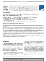
Purpose: With the increased commercial availability of intensity modulated arc therapy (IMAT)<br />
comes the need for <strong>comprehensive</strong> QA programs, covering the different aspects of this newly available<br />
technology. This manuscript proposes such a program for the <strong>RapidArc</strong> (RA) (Varian Medical<br />
Systems, Palo Alto) IMAT solution.<br />
Methods: The program was developed and tested out for a Millennium120 MLC on iX Clinacs and<br />
a HighDefinition MLC on a Novalis TX, using a variety of measurement equipment including Gafchromic<br />
film, 2D ion chamber arrays (Seven29 and StarCheck, <strong>PTW</strong>, Freiburg, Germany) with inclinometer<br />
and Octavius phantom, the Delta4 systam (ScandiDos, Uppsala, Sweden) and the portal<br />
imager (EPID). First, a number of complementary machine QA tests were developed to monitor the<br />
correct interplay between the accelerating/decelerating gantry, the variable dose rate and the MLC<br />
position, straining the delivery to the maximum allowed limits. Second, a systematic approach to<br />
the validation of the dose calculation for RA was adopted, starting with static gantry and RA specific<br />
static MLC shapes and gradually moving to dynamic gantry, dynamic MLC shapes. RA plans<br />
were then optimized on a series of artificial structures created within the homogeneous Octavius<br />
phantom and within a heterogeneous lung phantom. These served the double purpose of testing the<br />
behavior of the optimization algorithm (PRO) as well as the precision of the forward dose calculation.<br />
Finally, patient QA on a series of <strong>clinical</strong> cases was performed with different methods. In<br />
addition to the well established in-phantom QA, we evaluated the portal dosimetry solution within<br />
the Varian approach.<br />
Results: For <strong>routine</strong> machine QA, the “Snooker Cue” test on the EPID proved to be the most sensitive<br />
to overall problem detection. It is also the most practical one. The “Twinkle” and “Sunrise”<br />
tests were useful to obtain well differentiated information on the individual treatment delivery components.<br />
The AAA8.9 dose calculations showed excellent agreement with all corresponding measurements,<br />
except in areas where the 2.5 mm fixed fluence resolution was insufficient to accurately<br />
model the tongue and groove effect or the dose through nearly closed opposing leafs. Such cases<br />
benefited from the increased fluence resolution in AAA10.0. In the <strong>clinical</strong> RA fields, these effects<br />
were smeared out spatially and the impact of the fluence resolution was considerably less pronounced.<br />
The RA plans on the artificial structure sets demonstrated some interesting characteristics<br />
of the PRO8.9 optimizer, such as a sometimes unexpected dependence on the collimator rotation<br />
and a suboptimal coverage of targets within lung tissue. Although the portal dosimetry was successfully<br />
validated, we are reluctant to use it as a sole means of patient QA as long as no gantry angle<br />
information is embedded.<br />
Conclusions: The all-in validation program allows a systematic approach in monitoring the different<br />
levels of RA treatments. With the systematic approach comes a better understanding of both the<br />
capabilities and the limits of the used solution. The program can be useful for implementation, but<br />
also for the validation of major upgrades. VC 2011 American Association of Physicists in Medicine.<br />
[DOI: 10.1118/1.3622672]<br />
I. INTRODUCTION<br />
Following Yu et al. 1 we use intensity-modulated arc therapy<br />
(IMAT) as a generic term to denote radiation therapy delivery<br />
based on a rotating intensity modulated cone beam. For<br />
IMAT, the MLC moves during beam-on as for dynamic<br />
IMRT. However, the intensity–modulation may also be<br />
partly accomplished by varying the dose rate, gantry speed,<br />
and possibly even the collimator angle. The first stepping<br />
stones for IMAT were laid down many decades ago. For an<br />
extensive topical review, we refer to the publication by Yu et<br />
al. 1 and the references mentioned therein. The widespread<br />
5146 Med. Phys. 38 (9), September 2011 0094-2405/2011/38(9)/5146/21/$30.00 VC 2011 Am. Assoc. Phys. Med. 5146
5147 Van Esch et al.: A <strong>comprehensive</strong> program for <strong>RapidArc</strong> implementation 5147<br />
implementation of the technique in <strong>clinical</strong> practice has only<br />
begun in the recent years because the major vendors of medical<br />
linear accelerator vendors have only recently begun to<br />
commercialize integrated IMAT solutions. These commercial<br />
implementations of IMAT are—at least partly—based<br />
on or facilitated by the work published by the different pioneering<br />
groups (for a detailed overview, again see Yu et al. 1<br />
and Refs. 2–5).<br />
As IMAT is a more complicated technique than IMRT in<br />
terms of treatment planning and delivery, the standard QA<br />
and commissioning procedures used for IMRT are not sufficient.<br />
For instance, IMAT beams may encompass more complicated<br />
MLC movements than usually seen for IMRT,<br />
including small MLC openings in large collimator openings<br />
and single MLC leaves sticking out <strong>into</strong> the beam. Thus, models<br />
and model parameters for the MLC transmission, tongue<br />
and groove, and rounded leaf ends that suffice for IMRT may<br />
be insufficient for IMAT. The optimization algorithm and<br />
possibly also the dose calculation engine differs for IMAT<br />
and requires separate commissioning and QA. Additionally,<br />
extra strain is put on the treatment machine performance<br />
because of, e.g., variable gantry speed and gantry angle dependent<br />
dose rate modulation. For these reasons, IMAT specific<br />
QA programs must be developed to ensure that the<br />
planned dose distributions correspond to the delivered ones<br />
and to ensure reliable, stable and reproducible delivery. 6–9<br />
Naturally, the QA procedures needed for IMAT depend on<br />
the chosen IMAT solution. Designing a proper QA and commissioning<br />
program for IMAT requires knowledge and understanding<br />
of how the IMAT solution is constructed and how<br />
the different parts interact. In this work we focus on the Varian<br />
implementation of IMAT called <strong>RapidArc</strong> (RA), using<br />
both the Varian treatment planning system (TPS) and the Varian<br />
linear accelerators. <strong>RapidArc</strong> treatment plan optimization<br />
in the Eclipse TPS is based on the work of Otto et al. 10<br />
In most cases, a RA delivery utilizes fewer monitor units<br />
(MUs) and is considerably faster than the corresponding<br />
dynamic IMRT treatment plan while preserving treatment<br />
plan quality (see, e.g., the review published by Palma et al. 4<br />
and the references mentioned therein). Shorter treatment times<br />
have obvious advantages including better patient throughput,<br />
improved patient comfort and, possibly, less intra fractional<br />
motion. Thus, a demand for a <strong>clinical</strong> implementation of RA<br />
is justified. For a Clinac to be RA compatible, it requires the<br />
appropriate controller software. Additionally, a separate RA<br />
license on the TPS side is mandatory. RA was originally<br />
advertised as a one arc technique. However, even though one<br />
arc is sufficient for a number of cases (e.g., prostate), two arcs<br />
are usually required for more complex cases (e.g., head and<br />
neck). 11–15 Multiple arc solutions are now fully supported by<br />
the system (Eclipse version beyond 8.9). QA for RA is often<br />
comprised of machine, TPS, and patient specific QA. For the<br />
latter, the patient specific treatment plan is usually recalculated<br />
on and delivered to a phantom containing some dose<br />
detectors, e.g., ionization chambers, diodes, or film. In addition,<br />
portal dosimetry and independent dose calculations can<br />
be employed. There have been several publications on patient<br />
specific QA (Refs. 16–26) and numerous planning studies<br />
Medical Physics, Vol. 38, No. 9, September 2011<br />
including comparisons of RA, IMRT, tomotherapy, and particle<br />
therapy. 26–47 However, when it comes to designing a <strong>comprehensive</strong><br />
QA and commissioning program including<br />
machine QA only little has been published. 6,7 Ling et al. 6<br />
have published the most commonly used paper on machine<br />
QA and commissioning and the tests they describe are part of<br />
the Varian recommendations. However, as pointed out by the<br />
authors, the tests they devise do not thoroughly test the complete<br />
system and leave room for improvement. 48,49 Further,<br />
Ling et al. do not consider patient specific QA nor TPS QA. It<br />
is the aim of the present work to present a <strong>comprehensive</strong><br />
commissioning and QA program for RA. This includes tests<br />
of the machine performance, the TPS and patient specific QA.<br />
II. METHODS AND MATERIALS<br />
A <strong>comprehensive</strong> QA program was developed and tested<br />
in two radiotherapy departments to encompass the two most<br />
commonly used MLC types for RA delivery. Both departments<br />
use the full Varian (Varian Medical Systems Inc, Palo<br />
Alto, CA) solution for RA delivery: optimizations and forward<br />
dose calculations (AAA) are performed within the<br />
Eclipse planning system and delivered through the Aria record<br />
and verify system. Some additional calculations were<br />
performed with an Eclipse 10.0 beta version. The Herlev<br />
University Hospital (Herlev, Denmark) has eight 2300iX<br />
Clinacs (Varian) with 6 and 15 MV photon beam, all<br />
equipped with a 120 Millennium MLC while the Clinique<br />
Sainte Elisabeth (Namur, Belgium) also has a Novalis TX<br />
Clinac (6MV, 6MV SRS, and 18MV) with a 120 high definition<br />
MLC and RA capability. All are equipped with a Varian<br />
aS1000 amorphous silicon (aSi) portal imager (EPID) with<br />
dosimetric (integrated) acquisition mode.<br />
The dosimetric equipment used during the RA implementation<br />
program is outlined in Table I. An Octavius phantom<br />
with a Seven29 2D ion chamber array (<strong>PTW</strong>, Freiburg,<br />
Germany) and VERISOFT analysis software is present in both<br />
centers, as is the <strong>PTW</strong> StarCheck ion chamber array and the<br />
included software. The Herlev hospital also has the Delta4<br />
system. Both centers have established a Gafchromic EBT<br />
film (International Specialty Products, Wayne, NJ) dosimetry<br />
program. The films are scanned by means of an Epson<br />
Flatbed (Epson Perfection V700) and converted to dose by<br />
means of the VERISOFT FILMSCAN (version 2.7) software. The<br />
VERISOFT FILMSCAN software allows automatic selection of the<br />
red color component only, performs a flatness correction<br />
(based on the scan of a nonirradiated film) and a conversion<br />
from density to absolute dose through a user defined calibration<br />
curve. Film analysis is performed with the VERISOFT<br />
(4.1) software.<br />
II.A. Machine QA<br />
Setting up a reliable and relevant machine QA protocol for<br />
RA delivery requires a clear understanding of the (presumed)<br />
interplay between the different players. A RA plan consists of<br />
a sequence of control points, each specifying the MLC position<br />
and gantry angle at a given cumulative MU output. In<br />
between subsequent control points, the MLC and gantry angle
5148 Van Esch et al.: A <strong>comprehensive</strong> program for <strong>RapidArc</strong> implementation 5148<br />
TABLE I. Overview of the used measurement equipment for the different parts of the RA validation protocol. Letters indicate during which phases the setups<br />
are used: I ¼ implementation, R ¼ <strong>routine</strong>, P ¼ problem investigation or U ¼ major upgrade.<br />
Gafchromic film<br />
þEpson scanner<br />
(þVERISOFT FILMSCAN)<br />
StarCheck þ BeamAdjust<br />
þinclinometer<br />
(þMATLAB)<br />
Seven29 þ Verisoft<br />
þinclinometer<br />
þMATLAB<br />
move from the original to the newly specified position while<br />
the beam remains on and delivers the specified amount of<br />
MU, lowering the dose rate, gantry, or MLC speed as needed.<br />
For the current RA solution, the control mechanisms behind<br />
the actual delivery are as follows. The nominal dose rate is<br />
specified by the user and is typically set to the maximum possible<br />
value for treatment efficiency reasons (i.e., 600 MU/min<br />
in our case). In Eclipse, the maximum gantry speed is limited<br />
to 4.8 deg/s and the maximum MLC speed is user definable,<br />
but set to the recommended value of 2.5 cm/s. At the treatment<br />
console two separate sequences are generated to control<br />
the Clinac behavior; one specifying the MLC positions versus<br />
gantry angle, the other specifying the MUs versus gantry<br />
angle. Before the actual delivery, the plan is checked for possible<br />
violations to predefined limits. The limits set at the<br />
machine are less stringent than in Eclipse to allow for some<br />
margin. The gantry speed has a range of 0.5–6 deg/s. Except<br />
for doseless segments, the MUs/deg are required to be larger<br />
than 0.2 but smaller than 20 (60 for the 6MV SRS mode).<br />
During delivery, control is taken by the slowest player: when<br />
less than 1.7 MU/deg are to be delivered, the gantry will<br />
move at maximum speed but the dose rate will drop below<br />
600 MU/min. 50 When more MU/degree are to be delivered,<br />
the maximum dose rate will be maintained and the gantry will<br />
slow down. If the MLC can not perform its movement<br />
adequately fast, it will not induce a drop in the dose rate (and/<br />
or a slowing down of the gantry) like it does in a dynamic<br />
IMRT delivery, but it will generate an interlock instead. 51<br />
A selection of tests has already been proposed by<br />
Ling et al. 6 As stated by the authors, these tests assess the correct<br />
behavior of the MLC as a function of MU, but do not<br />
include any verification of the angular accuracy as the film (or<br />
EPID) is mounted to the gantry. In addition, we have therefore<br />
developed a number of tests that focus on the gantry performance<br />
in relation to the MUs and MLC position, respectively.<br />
Machine QA TPS validation<br />
Static Twinkle Dynamic Twinkle Sunrise Snooker Cue AAA PRO þ AAA Patient QA<br />
I,P I,P I,P — I,P a<br />
I,P I,P I,P — — — —<br />
I,P I,P I,P — — — —<br />
þsolid water — — — — I,P — —<br />
þOctavius phantom — — — — — I,U I,R<br />
Delta4 — — — — — I,U I,R<br />
EPID — — — I,U,R b<br />
— — I,R c<br />
a Including at least one additional ion chamber point measurement for absolute dose verification.<br />
b Including the placement of a metal rod, protruding from a block on the treatment couch.<br />
c To be used in combination with at least one additional check such as an ion chamber point dose measurement or an independent point dose calculation.<br />
Medical Physics, Vol. 38, No. 9, September 2011<br />
I,U a<br />
I,(R) a<br />
The dose rate, gantry speed and MLC trajectory of these tests<br />
is shown in Fig. 1:<br />
II.A.1. Static MLC Twinkle: assessing the accuracy of<br />
dose rate modulation versus gantry angle (maximum<br />
acceleration and deceleration).<br />
The “Static Twinkle” [Fig. 1(a)] is an artificially programmed<br />
RA delivery during which the MLC leaf positions<br />
remain in a stationary position, forming a 1 mm wide central<br />
gap. Dose is only delivered from a limited amount of narrow<br />
angular sectors (2 each), separated by larger (38 each) doseless<br />
sectors. During the doseless segments, the gantry moves<br />
at maximum speed. For the narrow sectors of dose delivery,<br />
the MUs and nominal dose rate are selected such that they<br />
require minimal gantry speed and therefore maximum deceleration<br />
or acceleration in between, straining the machine performance<br />
to the allowed limit. By decreasing the total amount<br />
of MUs, the same plan can also entirely be delivered at constant<br />
gantry speed eliminating the effects of acceleration and/<br />
or deceleration for comparison. To simulate possible problems,<br />
artificial errors were introduced <strong>into</strong> the RA delivery. A<br />
too slow response in the gantry movement is simulated by<br />
shifting the dose rays over 1 ,2, and 3 ,respectively.An<br />
overly smoothened gantry steering is simulated by broadening<br />
the rays by 1 ,2 , and 3 , respectively.<br />
II.A.2. Dynamic MLC Twinkle: assessing the accuracy<br />
of MLC movement versus gantry angle (maximum<br />
MLC speed)<br />
The Dynamic MLC Twinkle [Fig. 1(b)] should result in a<br />
measurement that is identical to the Static Twinkle, but the<br />
MLC positions no longer remain static during the doseless<br />
angular sectors; they perform a sweeping motion at maximum<br />
leaf speed. They are programmed to have returned to the
5149 Van Esch et al.: A <strong>comprehensive</strong> program for <strong>RapidArc</strong> implementation 5149<br />
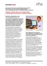
FIG. 1. Polar graphs displaying the programmed dose rate, gantry speed and MLC leaf positions as a function of gantry angle for (a) the Static MLC Twinkle,<br />
(b) the Dynamic MLC Twinkle, (c) the Sunrise and (d) the Snooker Cue for machine QA.<br />
central gap position at the start of the narrow dose ray delivery<br />
and should not move away from this position until the dose<br />
delivery over this angular sector has completed. Imperfections<br />
in the synchronization between leaf position and gantry<br />
Medical Physics, Vol. 38, No. 9, September 2011<br />
movement will result in narrowing, broadening or angular displacement<br />
of the rays. Such errors are again simulated by programming<br />
0.2, 0.5, and 1 mm errors in the MLC positions of<br />
the artificial files.
5150 Van Esch et al.: A <strong>comprehensive</strong> program for <strong>RapidArc</strong> implementation 5150<br />
II.A.3. Sunrise: assessing the impact of gantry speed,<br />
gravity and inertia on the gantry angle precision<br />
The Sunrise delivery [Fig. 1(c)] consists of adjacent dose<br />
sectors (of 20 each) of increasing total dose levels when<br />
moving from gantry 270 to gantry 0, subsequently decreasing<br />
again when moving from gantry 0 to gantry 90. The arc<br />
is programmed to be perfectly symmetrical around gantry 0.<br />
Dose is delivered through a narrow (1 mm) static MLC<br />
opening with constant gantry speed within each angular sector<br />
but subsequent sectors require a different amount of MUs<br />
per sector. The MUs are chosen sufficiently high to enforce<br />
maximum dose rate throughout the whole delivery and to<br />
impose minimum gantry speed in the highest dose sectors<br />
and maximum speed in the lowest dose sectors. Whereas<br />
gravity is opposing the gantry’s inertia during the upward<br />
gantry motion (270–0), it adds to the inertia in the downward<br />
trajectory (0–90). The transition from one sector to the next<br />
is a sharp one and—if present—gravitational effects on the<br />
delivery are expected to show up at the borderlines, causing<br />
an asymmetry in the delivered dose. Here again, artificial<br />
errors were introduced to simulate such effects.<br />
II.A.4. Snooker Cue: combining MU versus gantry<br />
angle and MLC movement in one single test<br />
A final test [Fig. 1(d)] was designed to allow a quick <strong>routine</strong><br />
assessment of the correct interplay between gantry<br />
angle, MLC position, and dose delivery in one single treatment<br />
plan by means of the EPID. Mounted to the gantry, the<br />
EPID has the major advantage that it allows extremely fast<br />
and easy measurement setup and data acquisition. As a disadvantage,<br />
it rotates along with the gantry so without additional<br />
input, the integrated image does not include gantry<br />
angle information. For the Snooker Cue test, a simple setup<br />
was attached to the end of the treatment couch consisting of<br />
a thin metal rod with a spherical tip (diameter ¼ 5 mm)<br />
mounted in the longitudinal direction with a lateral and vertical<br />
displacement from the isocenter of 5 cm and 10 cm,<br />
respectively. The MLC was programmed to have a constant<br />
gap of 1 cm between opposing leaves at all times. The position<br />
of the gap was programmed such that for a selection of<br />
gantry angles, the metal rod should be precisely in the centre<br />
of the projection of the MLC gap, while making sure that<br />
subsequent projections of the gap (at source imager distance<br />
150 cm) remain clearly separated. Dose delivery was programmed<br />
solely for narrow angular sectors (0.4 deg) around<br />
these discrete gantry angles, again assuring maximal gantry<br />
acceleration and deceleration between doseless and maximal<br />
dose rate delivery. In addition, the displacement of the MLC<br />
Medical Physics, Vol. 38, No. 9, September 2011<br />
gap from one position to another was delayed as long as necessary<br />
to enforce maximum leaf speed before coming to an<br />
abrupt halt at the moment of dose delivery. The treatment<br />
plan is subdivided <strong>into</strong> four subarcs with one integrated<br />
image each, to allow a clear distinction between the gap projections<br />
of the different quadrants. The treatment plan was<br />
programmed in clockwise as well as in counter clockwise<br />
direction.<br />
The tests were performed using different measurement<br />
methods (Table I and Fig. 2):<br />
II.A.4.a. Gafchromic film. For the Twinkle and Sunrise<br />
tests, first, gafchromic film was cut <strong>into</strong> 10 10 cm 2 pieces.<br />
For each test, one such piece was placed between two custom<br />
cut (10 10 5cm 3 ) solid water blocks and positioned<br />
on the treatment couch in the transversal plane through the<br />
isocenter. The isocenter (and the gantry zero position) is<br />
marked on the film with four black dots. The film is then<br />
irradiated with the test field and inspected visually on the<br />
spot, but left to fully auto develop overnight before being<br />
scanned. The films are scanned and converted to dose by<br />
means of the VERISOFT software, automatically extracting the<br />
red component from the film. A scan of a large nonirradiated<br />
film is used as a background and flatness correction.<br />
II.A.4.b. 2D ion chamber array with additional<br />
inclinometer. A second, alternative setup was developed for<br />
the Twinkle and Sunrise tests, aiming to avoid the use of<br />
film in <strong>clinical</strong> <strong>routine</strong>. A special fixation plate was made to<br />
mount the StarCheck or Seven29 ion chamber array together<br />
with an inclinometer (FAS-A, MicroStrain, Williston) to the<br />
tray holder of the Clinac. The inclinometer signal (gantry<br />
angle) and the array data (integrated dose) are read out<br />
simultaneously every 100 ms (StarCheck) or 200 ms<br />
(Seven29). A dedicated software interface was written in<br />
MATLAB (MathWorks, MA) to allow data processing and visualization<br />
of the acquired data as a function of gantry angle.<br />
II.A.4.c. EPID: The “Snooker Cue” RA fields were<br />
imported <strong>into</strong> Eclipse, scheduled and measured through Aria<br />
with the EPID at a source axis distance of 150 cm and using<br />
the integrated image acquisition mode. The images can be visually<br />
evaluated on-line or in the offline review software but<br />
need to be evaluated in the Eclipse Portal Dosimetry workspace<br />
if absolute dose information is to be obtained as well.<br />
II.B. TPS validation<br />
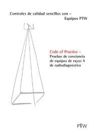
FIG. 2. Experimental setups for the machine QA tests:<br />
(a) Gafchromic film in transversal plane through the<br />
isocenter in 10 10 cm 2 solid water blocks, (b) 2D ion<br />
chamber array with inclinometer mounted to the tray<br />
holder of the Clinac and (c) EPID with metal rod<br />
placed on the treatment couch.<br />
II.B.1. AAA validation for manually programmed<br />
RA-specific fields<br />
In the Eclipse environment, the total dose of a RA plan<br />
delivery is calculated by means of the AAA algorithm 52,53 as
5151 Van Esch et al.: A <strong>comprehensive</strong> program for <strong>RapidArc</strong> implementation 5151<br />
the sum of a large number of static gantry, dynamic MLC<br />
fields. The default calculation settings are such that every<br />
control point is represented by one such static field. Even<br />
though the dose calculation makes use of a previously<br />
known and validated algorithm, 53,54 the conditions under<br />
which it is now used are usually not covered by the standard<br />
validation tests, neither for static nor for dynamic MLC<br />
treatments. The dose calculation algorithm fundamentally<br />
differs from static MLC calculations as it makes use of an<br />
interpolated photon fluence, taking the linear MLC movement<br />
in between control points <strong>into</strong> account. This is an<br />
approach similar to the IMRT dose calculation. However,<br />
the changing angular incidence in between control points is<br />
ignored and the fluence is assumed to originate from the gantry<br />
angle specified by the control point. Obviously, the angular<br />
resolution of the control points needs to be sufficiently<br />
high for this approximation to be valid. Should the user wish<br />
to do so, the angular calculation resolution can be changed<br />
from the default control point based resolution to a fixed<br />
angular resolution (1 –5 ). In addition, one needs to bear in<br />
mind that the typical MLC shapes appearing in a RA delivery<br />
are usually not represented within the standard validation<br />
package of a dose calculation algorithm (e.g. AAPM guidelines).<br />
Some of the segments have very small and/or off-axis<br />
effective openings in relatively large collimator openings,<br />
representing a challenge for the accurate absolute dose calculation.<br />
In addition, leaf pairs with nearly closed MLC tips (0.6<br />
mm opening) within the field are commonly observed. The<br />
importance of the resolution of the calculation grid is therefore<br />
another item to be investigated. As leaf movement can<br />
sometimes be highly asynchronous, it is expected to give rise<br />
to considerable tongue and groove effects, only modeled in<br />
the recent versions of the fluence calculator (Leaf Motion<br />
Calculator version 8.6 and later).<br />
To assess the impact of these RA-specific parameters<br />
(MLC parameters, small, off-axis MLC fields in large collimator<br />
opening, angular, and calculation grid resolution), we<br />
have first performed a number of tests on individual static<br />
fields followed by a set of artificially programmed arc deliveries.<br />
The values used for the dosimetric leaf gap (DLG)—<br />
modeling the rounded leaf tips—and leaf transmission are<br />
the ones determined during the implementation of IMRT by<br />
means of the Dynamic Chair 55 and the Sweeping Gap 56 tests.<br />
The tongue- and groove parameters are predefined for each<br />
type of MLC and can not be modified by the user. For all<br />
tests, calculations were performed with the calculation grid<br />
set to 2.5 and 1 mm. Except where indicated otherwise, the<br />
default control point angular resolution was used for the arc<br />
calculations. Tests were performed for both MLC types and<br />
for all available photon energies.<br />
The tests visualized in Fig. 3 were mostly performed in a<br />
rectangular phantom, (consisting of 30 30 cm 2 solid water<br />
plates), at a depth of 5 cm and SSD ¼ 95 cm (for<br />
gantry ¼ 0 ). Only the machine QA tests that were also used<br />
for the validation (Static MLC Twinkle and Sunrise) were<br />
performed in the setup described in the previous paragraph.<br />
Measurements were performed with Gafchromic films, but<br />
the absolute dose level of the film was always double<br />
Medical Physics, Vol. 38, No. 9, September 2011<br />
checked by means of measurements with the StarCheck, the<br />
Seven29 or a single ion chamber (<strong>PTW</strong> 0.125 cc Semiflex).<br />
The drawings in Fig. 3 correspond to the Millennium120<br />
MLC setup. They would be very similar for the HD MLC,<br />
apart from the amount of leaves involved in the 4 4cm 2<br />
central opening and the position of the jaws relative to the<br />
leaves.<br />
The first tests [Fig. 3(a)] aim to simultaneously address the<br />
modeling of the rounded leaf tips (DLG) and the small, offaxis<br />
MLC openings in relatively large collimator settings. The<br />
field size was chosen such that the measurement includes information<br />
on both leaf widths for both MLCs (i.e., 5 mm and<br />
1 cm leaves for the 120Millennium MLC, 2.5 and 5 mm<br />
leaves for the HD MLC) while not exceeding a total size of<br />
24 cm to remain within the maximum dimensions of the film<br />
or the 2D array. For the setup displayed in Fig. 1(a), four<br />
MLC files were created in which the central leaves always<br />
form a 4 4cm 2 open square, while all the other leaves line<br />
up to form a very narrow gap of 1, 3, and 5 mm, respectively.<br />
The second test setup is very similar to the first, except that all<br />
the leaf positions were shifted 10 cm off-axis.<br />
Additionally, the absolute dose in the centre of the 4 4<br />
cm 2 openings was measured for an extended range of main<br />
collimator settings—varying from a 4 4 to a 24 40<br />
cm 2 —to assess the accuracy of the MU calculation.<br />
Second, Fig. 3(b) shows the test used to assess the modeling<br />
of the tongue and groove effect in a worst case scenario:<br />
two static fields were delivered with complementary patterns<br />
of extended and retracted leaves. Again, the central leaves<br />
were kept in an open position in both fields to permit a reliable<br />
absolute ion chamber point dose measurement. Like in<br />
the first test, the collimator settings were chosen to include<br />
both leaf widths.<br />
In Figs. 3(c)–3(e), the aspects of the above tests are combined<br />
<strong>into</strong> an arc delivery and calculation. These tests were<br />
performed for a limited arc section to obtain higher measurement<br />
precision (i.e., with no significant angular dependence<br />
of the measurement equipment) and allow high resolution<br />
calculations while keeping calculation times reasonable. The<br />
MLC files were programmed to mimic both simple<br />
[Fig. 3(d)] and extreme [Fig. 3(e)] movements that will be<br />
generated by the RA optimizer: RA treatment planning aims<br />
for maximum gantry speed at all times and therefore will not<br />
allow MLC movements beyond 0.52 cm/deg (i.e., 2.5 cm/<br />
4.8 ). Every MLC pair was programmed to perform a 2 cm<br />
sweeping gap motion at maximum speed over a total trajectory<br />
of 8 cm per leaf, while the gantry is also rotating at<br />
maximum speed, moving from 345 to 15 . At 600 MU/min<br />
this requires a 63 MU delivery. Increasing the MU will cause<br />
the gantry rotation to slow down, decreasing the MUs below<br />
63 is likely to cause an MLC interlock during delivery. In<br />
setup d, the leaves perform a perfectly synchronous movement,<br />
all moving simultaneously from left to right and back.<br />
In setup e, adjacent leaves move in opposing directions,<br />
sweeping either from left to right (and back) or from right to<br />
left (and back), thereby introducing the dosimetric consequences<br />
of the tongue and groove shapes in the MLC leafs.<br />
Again, field sizes were chosen to include both leaf types <strong>into</strong>
5152 Van Esch et al.: A <strong>comprehensive</strong> program for <strong>RapidArc</strong> implementation 5152<br />
FIG. 3. Schematic overview of the MLC shapes and the field sizes used for the basic validation of the dose calculation. The drawings correspond to the Millenium120<br />
MLC setup, but are very similar for the HD MLC. The cross marks the CAX and the d indicates the leaf gap(s) between opposing leaf tips. The collimator<br />
settings are indicated first for the central setup and second for the laterally or longitudinally shifted setup. All measurements were performed at a depth<br />
of 5 cm and SSD ¼ 95 cm, except the Static Twinkle and Sunrise test which were performed in the setup shown in Fig. 2.<br />
Medical Physics, Vol. 38, No. 9, September 2011
5153 Van Esch et al.: A <strong>comprehensive</strong> program for <strong>RapidArc</strong> implementation 5153<br />
the measurement. For the actual delivery, two control points<br />
suffice to describe the entire movement as the MLC controller<br />
automatically performs an interpolation to generate its<br />
own 50 ms check points during the delivery. Even so, a series<br />
of MLC files were created, all corresponding to what<br />
should be the same delivery, but with varying degrees of<br />
angular resolution in the control points, ranging from control<br />
points every 15 (i.e., most simplistic, original treatment<br />
delivery file) to every 3 and 1.5 . For all resolution levels,<br />
measurements were performed and the corresponding dose<br />
was calculated with the default control point based angular<br />
resolution. In addition, the calculations were rerun with the<br />
angular resolution level modified to a fixed value of 1 .<br />
II.B.2. Performance assessment of the RA<br />
optimization algorithm<br />
The RA plan optimization in the Eclipse environment is<br />
performed by the progressive resolution optimizer (PRO8.9)<br />
algorithm. After having defined the isocenter, the dose prescription<br />
and the angular range of the arc(s) to be used, the<br />
user launches the optimization. It has a similar interface as<br />
the IMRT optimizer, allowing the user to specify upper,<br />
lower or line constraints on the target volumes and organs at<br />
risk (OAR), each with its own priority. A user definable normal<br />
tissue objective applies a penalty to the normal tissue<br />
dose as a function of the distance to the target volume aiming<br />
to reduce hot spots outside the target volume(s). An additional<br />
constraint (minimum and maximum) can be applied to<br />
the total amount of MU and avoidance sectors can be<br />
defined. Before starting the actual optimization process, the<br />
user has the possibility to launch the automatic optimization<br />
of the collimator angle, the isocenter position and the couch<br />
rotation. The main collimator opening as determined at the<br />
start of the PRO optimization process remains fixed during<br />
the whole arc delivery.<br />
In contrast to the Eclipse IMRT process, the PRO is not<br />
an optimal fluence based but a direct aperture optimizer. 10<br />
Optimization of the leaf positions is performed during five<br />
subsequent “resolution levels”. Each level is characterized<br />
by a predefined increase in angular resolution. For a 360<br />
arc, at the first resolution level (i.e., at the start of the optimization)<br />
about 10 equi-angular fields are used. The initial<br />
positions of the leaves are set to conform around the target<br />
volume. The MLC aperture is then optimized according to<br />
the constraints, but always such that the leaf motions do not<br />
violate the maximum allowed leaf speed. At the second resolution<br />
level, the amount of fields is doubled and the MLC<br />
aperture is optimized further. At the third, fourth and fifth<br />
level, the amount of fields is again increased and the field<br />
aperture optimized, resulting in a final angular resolution of<br />
around 2 . The user can interactively change the constraints<br />
and priorities during the course of all levels, but the response<br />
of the algorithm to such changes is at its most efficient during<br />
the first resolution level.<br />
Evaluating the performance of a new algorithm by means<br />
of real patients is a difficult and often inadvertently subjective<br />
task. Because of the patient specific volumes, plan comparisons<br />
Medical Physics, Vol. 38, No. 9, September 2011<br />
are often difficult to interpret in terms of target coverage and<br />
target conformity versus organ sparing. In addition, the<br />
results depend substantially on the experience and time spent<br />
by the planner on one technique or the other. In order to limit<br />
these intrinsic problems in algorithm evaluations, we present<br />
a set of simple geometric structures, meant to mimic simplified<br />
<strong>clinical</strong> cases. Some of the structures are similar to the<br />
ones proposed in the AAPM TG-119 IMRT commissioning<br />
test instructions while others have been added to provide a<br />
more extensive training and validation set for arc treatments.<br />
Except for the “‘Lung,” all structure sets were contoured on<br />
a scan of the homogeneous Octavius phantom with solid<br />
water inserts in the cavity for the Seven29. A selection of the<br />
used geometric structure sets is illustrated in Fig. 4.<br />
- Central and off-axis cylinder [Fig. 4(a)]: Two simple cylinders—one<br />
central (diameter 10 cm) and one off-axis cylinder<br />
(diameter 5 cm) at a 5 cm off-axis position—are used<br />
to investigate central versus off-center RA treatments. For<br />
RA treatments, the isocenter must often remain in the center<br />
of the patient even if the target is not, as lateral movement<br />
of the treatment couch must be limited to avoid<br />
collisions during the arc movement of the gantry.<br />
- Spherical prostate [Fig. 4(b)]: this structure set consists of<br />
a spherical prostate and a cylindrical rectum and bladder.<br />
- Cylindrical prostate with seminal vesicles (not shown):<br />
this structure set consists of three cylindrical structures<br />
(prostate, rectum, bladder) and two half-moon structures<br />
alongside the “prostate” cylinder to represent the seminal<br />
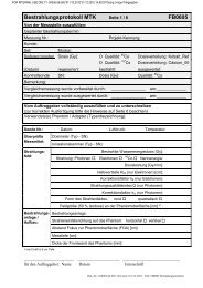
FIG. 4. Some illustrations of the artificial structures contoured in the Octavius:<br />
(a) central and off-axis cylinder, (b) spherical prostate with bladder<br />
and rectum, (c) horseshoe-shaped head and neck volume with two PTVs, (d)<br />
oesophagus and spinal cord tilted cylinders, (e) spiral shaped Snake structure.<br />
Heterogeneity tests were performed in the home made inhomogeneous<br />
lung phantom displayed in (f).
5154 Van Esch et al.: A <strong>comprehensive</strong> program for <strong>RapidArc</strong> implementation 5154<br />
vesicles and generate a more concave total target, around<br />
an organ at risk. This structure set can also be used to simulate<br />
integrated boost treatments with different simultaneous<br />
dose/fraction prescriptions to different volumes.<br />
- Head and Neck (with one or two PTV structures) [Fig.<br />
4(c)]: A horseshoe-shaped large PTV and a slightly offaxis<br />
cylindrical volume simulate a simplified head and<br />
neck situation, including a cylindrical structure as the spinal<br />
cord or brainstem and two half-moon cylinders alongside<br />
the larger PTV to represent the parotid glands.<br />
- Oesophagus [Fig. 4(d)]: A tilted cylindrical volume simulates<br />
an elongated target volume with increasing depth in<br />
the longitudinal direction. A “spinal cord” cylinder runs<br />
parallel along the target.<br />
- Snake [Fig. 4(e)]: The “snake” is a highly complex, spiral<br />
shaped tube designed to challenge both the optimization<br />
and the delivery.<br />
- Lung [Fig. 4(f)]: A lung phantom was constructed out of<br />
30 30 cm 2 solid water plates and 5 10 cm 2 custom cut<br />
solid water and cork building blocks of variable thicknesses<br />
(ranging from 2 mm to 5 cm). A solid water<br />
“mediastinum” with protruding lobes was thus constructed<br />
in between two cork lung structures. A first rectangular target<br />
volume was contoured including the right lobe and<br />
extending to the middle of the mediastinum. A second, cylindrical<br />
target volume was contoured in the upper part of<br />
the central pillar of the mediastinum.<br />
For all of the above structure sets, a series of RA plans<br />
were optimized, exploring the different options that can be<br />
employed during optimization (e.g., collimator rotation, isocenter<br />
optimization, …). Plans were generated in both centers<br />
for the Millennium120 and in Namur for the HD MLC.<br />
When optimizing different plans on the same structures but<br />
with changing initial conditions (e.g., user defined versus<br />
automatically optimized collimator rotation), the exact same<br />
criteria (constraints and priorities) were used to allow systematic<br />
inter comparison of the different plans. To evaluate<br />
target coverage, we make use of the mean, maximum and<br />
minimum doses. We also calculate the conformity index for<br />
the 95% isodose level (CI95) as a quick initial assessment in<br />
combination with visual isodose evaluation:<br />
CI95 ¼ V95=VPTV:<br />
As the conformity index itself only assesses the size of the<br />
95% volume but not its anatomical location with respect to<br />
the target volume it should be used with caution and never<br />
as a sole decisive factor. 57,58 To allow more detailed quantitative<br />
assessment we have made use of two additional criteria,<br />
the lesion coverage fraction (LCF, also referred to as the<br />
lesion CoVerage factor CVF) and the normal tissue overdosage<br />
fraction (NTOF). 58 The LCF measures the fraction of<br />
the PTV that is covered by the desired isodose level (e.g.,<br />
95%). If the PTV was not entirely within the 95% isodose,<br />
we used the Boolean operators available in the Eclipse contouring<br />
workspace to create a “PTVand95” structure, composed<br />
of all pixels that belong to both the PTV and to the<br />
structure generated from the 95% isodose. The LCF is then<br />
Medical Physics, Vol. 38, No. 9, September 2011<br />
calculated by taking the ratio of the volume of the<br />
PTVand95 structure to the PTV volume:<br />
LCF95 ¼ VPTVand95=VPTV:<br />
If the PTV is entirely within the 95% isodose, obviously,<br />
VPTVand95 equals VPTV and LCF95 therefore equals unity. In<br />
addition to the LCF value, a measure for the relative amount<br />
of high dose delivered outside of the PTV is obtained by subtracting<br />
all PTV pixels from the 95% dose volume to obtain a<br />
“95subPTV” structure. The ratio of the volume of this structure<br />
to the volume of the 95 isodose structure yields the<br />
NTOF95: NTOF95 ¼ V95subPTV=V95:<br />
The NTOF is very similar to the healthy tissue overdosage<br />
factor (HTOF) parameter described in Ref. 58, except that<br />
we have chosen to normalize to the V95 instead of to the<br />
PTV volume, in order to quantify the percentage of the 95%<br />
dose volume that is delivering “useless” dose to normal tissue.<br />
In plans of good quality, were the 95% isodose line<br />
closely encircles the PTV, both parameters yield approximately<br />
the same values.<br />
The ideal target coverage would be characterized by a<br />
CI95 and LCF95 close to unity and NTOF95 approaching<br />
zero. Inter comparison of the above values for different plans<br />
on the same target volumes allows quantitative interpretation<br />
of the relative plan quality.<br />
II.B.3. AAA validation of RA plans on artificial<br />
structures<br />
For all of the above generated plans, measurements were<br />
performed in a phantom and compared to the corresponding<br />
dose calculation. Three different verification methods were<br />
used in parallel:<br />
- Gafchromic film in the homogeneous Octavius phantom<br />
(“red face”) or in the Lung phantom<br />
- Seven29 in the Octavius phantom (“black face”)<br />
- Delta4 (ScandiDos, Uppsala, Sweden)<br />
The use of Gafchromic films is an established method for<br />
general phantom QA, 59 as is the Seven29-Octavius combination<br />
for arc measurements. 60 The reliable absolute dose level<br />
but limited resolution of the Seven29 measurement is complemented<br />
by the more cumbersome, but high resolution<br />
film measurement. Horizontal (coronal) and vertical (sagittal)<br />
planes were measured with the first two methods. The<br />
additional use of the Delta4 QA solution allows dose acquisition<br />
in two diagonal planes and provides an additional<br />
dataset for every plan. (Although the Octavius phantom also<br />
allows easy acquisition of diagonal planes, the corresponding<br />
calculated planes can currently not be exported from<br />
Eclipse nor can they be reconstructed in the current version<br />
of the VERISOFT software from the 3D dose export. Therefore,<br />
the diagonal planes were not acquired for the Octavius set<br />
up.) The goal of using three different measurement methods<br />
is to more extensively test the accuracy of the dose delivery
5155 Van Esch et al.: A <strong>comprehensive</strong> program for <strong>RapidArc</strong> implementation 5155<br />
and calculation, while simultaneously testing out and inter<br />
comparing the different QA solutions for later use in <strong>clinical</strong><br />
<strong>routine</strong>.<br />
For the film verification, no dose recalculation on a phantom<br />
needed to be done as the film was irradiated in the same<br />
setup as was used for the optimization and forward calculation.<br />
Film processing and analysis was performed as<br />
described at the onset of the materials and methods section.<br />
For the comparison with the calculated dose in the measurement<br />
plane, we exported both the 2D dose plane and the<br />
3D dose matrix, to allow gamma analysis in two and three<br />
dimensions. 61,62 For the second and third phantom verification<br />
method, the original plan was transferred to the appropriate<br />
phantom (Octavius CT scan with the Seven29 and<br />
Delta4 cylindrical phantom, respectively) and the dose was<br />
recalculated. The presence of the treatment couch was<br />
always taken <strong>into</strong> account. 63<br />
II.C. Patient QA<br />
Although less important during the validation of a new<br />
technique, the efficiency of the QA process becomes a critical<br />
factor for the success with which the new technique can be<br />
transferred <strong>into</strong> <strong>clinical</strong> <strong>routine</strong>. We have focused on the two<br />
most common methods that are currently available (or in a<br />
final testing phase) to the medical physicist: phantom QA and<br />
portal dosimetry. For a cohort of ten patients with varying<br />
treatment sites, we have performed both patient specific QA<br />
methods and compared the results for consistency. We introduced<br />
some errors such as suboptimal MLC parameters and<br />
lack of couch modeling to test the respective sensitivity to<br />
error detection. We have monitored the time needed for each<br />
of the methods, distinguishing between preparation and analysis<br />
time and the time spent at the treatment machine.<br />
II.C.1. Phantom QA<br />
For RA patient QA in a phantom, we have used the exact<br />
same methods as described above for the general validation<br />
of the RA process, namely the Octavius/Seven29 combination<br />
(in the horizontal and vertical measurement plane<br />
setup), the Delta4 system and film. Although a new plan was<br />
created to calculate and export the expected dose in the<br />
phantom, at the treatment console, we did not deliver this<br />
copy but made use of the newly available (8.9) “QA mode”<br />
to deliver the actual patient plan to the phantom. The QA<br />
mode does not register the delivered session and therefore<br />
allows (repetitive) verification of the treatment plan without<br />
interfering with the recorded patient dose.<br />
II.C.2. Portal dosimetry<br />
Portal dose images were acquired with the aS1000 EPID<br />
using the dosimetric acquisition mode, integrating the delivery<br />
during the whole arc motion. The dosimetric calibration<br />
of the imager panel was performed at a source imager distance<br />
of 100 cm and included a two dimensional profile correction<br />
64,65 instead of the official profile correction based on<br />
a diagonal 40 40 cm 2 field profile measurement at d max.<br />
Medical Physics, Vol. 38, No. 9, September 2011<br />
The source imaging distance was 100 cm to maximize the<br />
range of field sizes that fit <strong>into</strong> the 40 30 cm 2 imaging<br />
panel. The radiation was delivered directly to the panel,<br />
without the treatment couch or any kind of phantom in the<br />
beam. Although the positional accuracy of the exact arm is<br />
known to be far superior to the older R-arm, it is still known<br />
to exhibit some sagging ( 1 mm) when rotated. To assess<br />
the impact of the sagging of the exact arm on the final image,<br />
a number of RA plans were converted <strong>into</strong> IMRT plans with<br />
the exact same MLC movement as a function of MU but<br />
with gantry zero.<br />
The expected portal dose images were calculated by means<br />
of the portal dose prediction algorithm available in the Eclipse<br />
10.0 beta version. This is fundamentally the same algorithm<br />
as used for the IMRT portal dose verification, 64 converting<br />
the total theoretical fluence <strong>into</strong> a portal dose image while taking<br />
the scatter characteristics of the aSi <strong>into</strong> account through a<br />
single pencil beam algorithm. As the EPID rotates along with<br />
the gantry, the gantry angle information in the treatment plan<br />
is not used during the prediction and the whole delivery is collapsed<br />
<strong>into</strong> the plane of the imager panel.<br />
Portal dose images were measured and calculated for all<br />
RA treatment plans produced on the artificial structures in<br />
Octavius and for all patient plans. The results were compared<br />
in the Portal Dosimetry software packaged of the 10.0<br />
Eclipse environment, mainly based on visual line profile<br />
comparison and 2D gamma calculation [using Gamma criteria<br />
of 3% (global dose), 3 mm and requesting at least 95%<br />
agreement when restricting the region of interest to the MLC<br />
CIAO].<br />
III. RESULTS<br />
From the results obtained from the diverse test set-ups,<br />
we have made an assessment of their general applicability in<br />
combination with the used equipment. Table I illustrates during<br />
which phase they are deemed to be most useful, i.e., during<br />
RA implementation (I), in <strong>routine</strong> (R) for problem<br />
investigation (P) or after a major upgrade (U).<br />
Detailed results on the different phases are presented<br />
below.<br />
III.A. Machine QA<br />
Results on the static MLC twinkle tests are illustrated in<br />
Fig. 5. The polar graphs of Fig. 5(a) show the theoretically<br />
programmed dose rate behavior as a function of gantry angle<br />
as solid gray bars. The lines represent the measurements,<br />
obtained from the simultaneous data acquisition with the inclinometer<br />
and the StarCheck 2D array. Correct delivery is<br />
illustrated in the upper graph. Only data for the central<br />
chamber are shown, but the results for the other chambers<br />
along the longitudinal axis of the StarCheck are very similar<br />
to the ones displayed. The expected Twinkle pattern is accurately<br />
reproduced by the measurement. The errors shown in<br />
the bottom part of Fig. 5(a) correspond to an artificially<br />
introduced gantry inertia effect of 3 (red line) and a 2<br />
smoothening effect of the gantry motion around the actual<br />
control point (green line). The inertia error shows up as a
5156 Van Esch et al.: A <strong>comprehensive</strong> program for <strong>RapidArc</strong> implementation 5156<br />
FIG. 5. Examples of machine QA measurements: (a) StarCheck and inclinometer data obtained for the Static MLC Twinkle data for correct delivery (upper polar<br />
plot) and delivery with intended errors (lower polar plot). The gray bars indicate the theoretically expected dose rate as a function of gantry angle. The<br />
errors shown in the lower part correspond to an artificially induced gantry inertia effect of 3 and a 2 smoothening effect of the gantry angle motion. (b) Film<br />
data obtained for the Static MLC Twinkle displaying correct delivery, induced inertia effect and overly smoothened delivery. All comparisons show the<br />
expected image, the measured film and the isodoses of the measurement overlayed on the expected image.<br />
clockwise shift of the angles at which the dose rate peaks are<br />
observed (except for the starting point, which correlates correctly<br />
as no inertia is present at the onset of the arc rotation).<br />
The smoothening error shows up as a widening of the<br />
observed dose rate peaks. Artificially introduced errors<br />
smaller than 1 (not shown) do not distort the measurement<br />
enough to be clearly visible. A similar sensitivity to error<br />
detection is observed when using films [Fig. 5(b)] instead of<br />
the StarCheck/inclinometer combination. Next to the<br />
expected and measured images, an overlay of both is displayed:<br />
the isodose lines indicating the measured rays coincide<br />
well with the expected rays (shown in grayscale) during<br />
correct delivery, but show a displacement or widening for<br />
the rays with artificially introduced errors. Errors of 1 or<br />
less are barely distinguishable. Results for the dynamic<br />
MLC Twinkle are very similar to the ones shown for the<br />
static MLC twinkle. After correct delivery, the obtained data<br />
Medical Physics, Vol. 38, No. 9, September 2011<br />
are identical to the static MLC Twinkle data. Artificially<br />
introduced errors in the MLC movement show up as a displacement,<br />
narrowing or widening of the dose rate peaks,<br />
resulting in polar graphs and images similar to the ones<br />
shown in Fig. 5.<br />
The Sunrise data obtained with the StarCheck/inclinometer<br />
tandem are evaluated by means of polar graphs displaying<br />
the measured dose (instead of the above used dose rate)<br />
as a function of gantry angle. Measurements showed an<br />
adequately sharp transition in gantry speed in between subsequent<br />
sectors and a stable gantry speed within the sectors.<br />
As theoretically intended, the dose rate remains at its maximum<br />
value of 600 MU/min during the whole delivery. (The<br />
planar dose distribution as measured by the film in the transversal<br />
plane is not shown here but elaborated on in Fig. 8(a),<br />
where it is also used for the validation of the dose calculation<br />
algorithm).
5157 Van Esch et al.: A <strong>comprehensive</strong> program for <strong>RapidArc</strong> implementation 5157<br />
The integrated image of one of the subarcs (gantry 270–<br />
0 ) of the Snooker Cue test is shown in Fig. 6(a). As can be<br />
seen, the metal rod remains in the center of the projected<br />
MLC gaps for all gantry angles. In contrast to the Twinkle<br />
and Sunrise measurements, programmed errors of 1 in the<br />
gantry position were already quite noticeable as the projection<br />
of the probe shifts notably out of its central position in<br />
the projection of the MLC gaps (Fig. 6(b)]. For gantry angle<br />
errors of 2 [Fig. 6(c)] or more, the probe’s projection drifts<br />
out of the MLC projection. A similar effect was observed for<br />
the plans containing a 1 and 2 mm intentional MLC error,<br />
FIG. 6. Integrated images of one of the subarcs of the Snooker Cue test: displaying<br />
the rod in the center of the projected MLC gaps for all gantry angles<br />
for the correct delivery (a) and the displaced projection of the metal rod in<br />
the vertical lines for the simulated inertia error of 1 (b) and 2 (c) (for all<br />
gantry angles except the starting angle).<br />
Medical Physics, Vol. 38, No. 9, September 2011<br />
simulating the hypothetical situation in which the MLC has<br />
not reached its target position in time or with insufficient<br />
accuracy.<br />
III.B. TPS validation<br />
III.B.1. AAA validation for manually programmed<br />
RA-specific fields<br />
For the static gantry MLC tests [Figs. 3(a) and 3(b)], we<br />
observe that the ion chamber measurements in the centre of the<br />
4 4cm 2 MLC openings agree within 2% with the calculated<br />
absolute dose for all collimator settings, for the central as well<br />
as for the off-axis MLC position. To evaluate the accuracy<br />
with which the different leaf gaps between opposing leaves are<br />
calculated, film data, and calculated dose planes are carefully<br />
aligned before extracting line profiles perpendicular to the<br />
leaves and precisely through the center of the leaf gap. Examples<br />
of such line profiles are shown in Fig. 7 for a 3 mm wide<br />
leaf gap for both MLC positions {central [Fig. 7(a)] and offaxis<br />
[Fig. 7(b)]} of the HD MLC. Although these data confirm<br />
the excellent absolute agreement in the 4 4cm 2 opening,<br />
they also demonstrate the fact that the height of the dose peak<br />
between the leaf tips is underestimated by the 8.9 AAA dose<br />
calculation. The agreement is much better for the data obtained<br />
for the 5 mm gap, but worse for the 1 mm leaf gap. Enhancing<br />
the calculation resolution from 2.5 to 1 mm results yields only<br />
a marginal improvement, as this resolution change only affects<br />
the AAA forward calculation but not the default 2.5 mm resolution<br />
of the fluence that is used as input for the AAA dose calculation.<br />
When recalculating the dose distribution with the<br />
10.0 beta version of the AAA algorithm, using a high resolution<br />
(0.3 mm) fluence calculation, near-perfect agreement with<br />
the measured data is observed for the 1 mm forward dose calculation<br />
resolution. The consequences of the improved resolution<br />
in the fluence calculation are also clearly visible in the<br />
tongue and groove test [Fig. 7(c)]: although the AAA 8.9 dose<br />
calculation reports an adequate average dose level, AAA 10.0<br />
actually reproduces the pattern of dips and peaks, even for the<br />
2.5 mm narrow central leaves of the HD MLC.<br />
The dynamic gantry, static MLC tests provide clear feedback<br />
on the impact of angular resolution. When performing a<br />
dose calculation purely based on the manually programmed<br />
control points, the calculated dose can differ substantially<br />
from the measured dose. Figure 8(a) illustrates the drastic<br />
effect of the 15 angular resolution of the Sunrise test on the<br />
dose calculation: instead of spreading the dose (delivered<br />
through the 1 mm static MLC opening) over the entire angular<br />
sectors, the dose calculation assumes the full dose to be delivered<br />
solely at the control points, resulting in an unrealistic<br />
star-like dose pattern. When changing to a fixed angular resolution<br />
of 3 , calculation results approach reality, although the<br />
star-like pattern is still visible as can be seen from the oscillations<br />
in the line profile. A fixed angular resolution of 1<br />
adequately reproduces the smooth dose delivery observed on<br />
film. A similar effect can be observed from the dynamic gantry<br />
sweeping gap test [Fig. 8(b)]: although an angular resolution<br />
of 15 suffices to produce the desired Clinac behavior, it<br />
results in an erroneous dose calculation. Again, setting the
5158 Van Esch et al.: A <strong>comprehensive</strong> program for <strong>RapidArc</strong> implementation 5158<br />
angular resolution to 1 rectifies the problem and results in<br />
good agreement between calculated and measured (film and<br />
2D array) dose levels. Line profiles corresponding to the arc<br />
delivery of the highly asynchronous MLC movement are<br />
shown in Fig. 8(c): in agreement with the above results on the<br />
static gantry tests, the high resolution fluence available to the<br />
AAA 10.0 version proves beneficial in the accurate modeling<br />
of the tongue and groove patterns. Even so, the 8.9 dose calculation<br />
version reports a dose level that corresponds well to<br />
the average film dose level and to the absolute dose level<br />
measured with the 2D array (5 5mm 2 ion chambers).<br />
III.B.2. Performance assessment of the RA<br />
optimization algorithm<br />
The artificial structure sets provide interesting insight in<br />
the behavior of the PRO8.9. A selection of planning results<br />
is listed in Table II for the Millennium120 MLC. When different<br />
plans are listed for the same structure set, all of them<br />
are obtained with identical constraints and priorities during<br />
Medical Physics, Vol. 38, No. 9, September 2011<br />
FIG. 7. Effect of the resolution on the calculation accuracy:<br />
Measured (film) (black line) and calculated doses<br />
(AAA 8.9 with 2.5 mm (dotted line) or 1 mm (solid<br />
line) resolution and AAA 10.0 (dashed line) with a 0.3<br />
mm fluence resolution and 1 mm dose calculation resolution)<br />
for (a) the central DLG test setup with a 3 mm<br />
gap between the leaf tips, (b) the off-axis test setup<br />
with a 3 mm gap between the leaf tips and (c) the<br />
tongue and groove setup.<br />
the optimization process to allow meaningful inter comparison.<br />
First, the automatic isocenter position and couch rotation<br />
parameter optimization, available at the onset of the RA<br />
optimization process was found to be of very limited use as<br />
this optimization process does not take possible collisions<br />
<strong>into</strong> account. Second, when requesting an automatic collimator<br />
rotation optimization, in all of the observed cases, the<br />
collimator was simply rotated over 45 . Although a 45 collimator<br />
rotation may present some mechanical advantages<br />
(such as a larger maximum field opening in the longitudinal<br />
direction), from the obtained plans it can be concluded that<br />
this “optimized” collimator rotation is not necessarily the<br />
best choice in all cases. An excellent RA plan is obtained for<br />
the central cylinder with collimator 0, resulting in a near-perfect<br />
coverage of the PTV (LCF ¼ 1) and only 3% of the 95%<br />
dose volume situated outside of the PTV. When using the<br />
automatic collimator rotation, although the CI is nearly identical<br />
to the one obtained for collimator zero plan, the LCF<br />
shows that 3% of the PTV is underdosed while the NTOF<br />
reports that 7% of the 95% dose deposition is situated
5159 Van Esch et al.: A <strong>comprehensive</strong> program for <strong>RapidArc</strong> implementation 5159<br />
outside of the PTV. This also illustrates the superiority of<br />
the LCF and NTOF over the use of the CI. A similar<br />
decrease in plan quality between collimator 0 and collimator<br />
45 is observed for the off-axis cylindrical PTV, the spherical<br />
prostate and the oesophagus, reaching extreme proportions<br />
for the complex snake-shaped target. For the more concave<br />
structures, such as the prostate with seminal vesicles and the<br />
horseshoe-shaped head and neck structures, better target<br />
coverage and dose homogeneity is obtained with the 45 collimator<br />
rotation. For both of these cases, no decent plans<br />
(single or double arcs) were obtained with collimator 0. The<br />
use of the double arc reduces the hot spots. The disadvantage<br />
Medical Physics, Vol. 38, No. 9, September 2011<br />
FIG. 8. Effect of the angular resolution on the calculation<br />
accuracy: (a) Sunrise test calculated with 15<br />
(dashed line), 3 (solid line) and 1 (solid black line)<br />
angular resolution. The position of the extracted line<br />
profiles is shown on the 2D dose images displayed on<br />
the right of the graph. (b) Dynamic gantry, sweeping<br />
gap test results for film (black line), 2D array (black<br />
squares), and AAA 8.9 dose calculations with an angular<br />
resolution of 15 (solid line) and 1 (dashed line).<br />
(c) Line profiles corresponding to the Tongue and<br />
groove arc, measured with film (solid black line) and<br />
the 2D array (black squares) and calculated with 1<br />
angular resolution and 1 mm dose grid resolution for a<br />
2.5 mm (dashed line) and 0.3 mm (solid line) fluence<br />
map resolution.<br />
of using a collimator zero could be the fact that tongue and<br />
groove effects of a single leaf pair superimpose <strong>into</strong> the<br />
same transversal plane and are therefore not smeared out<br />
during the gantry motion as is the case with a collimator<br />
rotation. We have therefore also performed RA optimizations<br />
for a much smaller (10 ) collimator rotation. Examples<br />
are shown for the simple central cylinder and the more complex<br />
horseshoe-shaped head and neck case, revealing inferior<br />
to extremely poor plan quality, respectively.<br />
From Table II, it can also be concluded that not too much<br />
weight should be attributed to the minimum and maximum<br />
volume doses as reported by the TPS when evaluating the
5160 Van Esch et al.: A <strong>comprehensive</strong> program for <strong>RapidArc</strong> implementation 5160<br />
TABLE II. Overview of the planning results for a number of RA plans on the artificial structure sets. Different plans listed for the same structure set were all<br />
obtained with identical constraints and priorities during the optimization process for meaningful inter comparison. The confirmity Index CI, the lesion coverage<br />
fraction, LCF, and the normal tissue overdosage fraction, NTOF, are calculated for the 95% isodose, according to the formulas listed in the manuscript.<br />
Plan<br />
Dose/fr<br />
(Gy) MU<br />
Collimator<br />
( )<br />
Field size<br />
(cm cm)<br />
VPTV<br />
(cm 3 )<br />
quality of a plan. None of the listed RA plans report a minimum<br />
dose of 95%, in contradiction to the fact that many of<br />
these plans report full PTV coverage by the 95% isodose<br />
line. When looking in detail at the dose volume histograms<br />
for the plans with LCF equal to unity, one observes that only<br />
a negligibly small fraction (typically smaller than 0.3%) of<br />
the PTV is actually receiving these lower doses. Similarly,<br />
the maximum dose value (PTV or 3D) should be looked at<br />
with equal caution and in combination with isodose lines or<br />
with percentage volumes of the concerned dose levels.<br />
Although this is an already known issue, even in conventional<br />
static treatments, its significance increases as plans<br />
become more modulated and as the existence of local dose<br />
peaks or dips (outside or within the PTV) becomes more<br />
probable, as is the case with RA plans.<br />
Both plans obtained on the heterogeneous lung phantom<br />
were renormalized to obtain 100% as a mean dose. (The<br />
renormalization was small enough not to jeopardize the lim-<br />
V95<br />
(cm 3 ) CI95 LCF95 NTOF95<br />
Dmean<br />
PTV(%)<br />
Dmin<br />
PTV(%)<br />
Dmax<br />
PTV(%)<br />
CylCentral 1 196 0 10.9 11.5 836.3 872.6 1.040 1.00 0.03 100.0 86.7 106.7 106.7<br />
171 10 12.4 12.5 952.0 1.138 1.00 0.12 100.0 90.4 106.1 106.1<br />
163 45 15.0 15.0 865.3 1.035 0.97 0.07 100.0 87.1 107.8 107.8<br />
10 1760 45 15.0 15.0 934.9 1.118 1.00 0.11 101.2 90.0 107.2 107.2<br />
Cyl OA 1 200 0 22.8 11.8 258.1 297.4 1.152 1.00 0.13 101.2 92.5 104.5 105<br />
45 22.5 22.0 325.8 1.262 1.00 0.21 102.1 88.7 107.1 107.1<br />
Prost 3D 2 496 0 5.7 5.6 80.2 82.6 1.030 0.99 0.02 97.5 77.6 107.5 107.5<br />
488 45 6.4 6.4 92.1 1.148 1.00 0.13 97.6 91.4 101.1 101.1<br />
Prost SV 2 492 0 9.0 8.7 199.2 221.4 1.111 0.92 0.19 99.6 68.4 115.5 115.5<br />
426 45 11.9 11.9 277.5 1.393 1.00 0.27 99.7 92.6 107.5 107.5<br />
320 00 9.0 8.7<br />
248.1 1.245 0.98 0.22 99.6 70.5 117.9 117.9<br />
326<br />
9.0 8.7<br />
224 45 11.9 11.9<br />
274.4 1.378 1.00 0.26 99.7 91 104.6 105.3<br />
247 315 11.9 11.9<br />
H&N_1PTV 2 329 0 14.5 11.7 638.9 199.1 0.312 0.29 0.08 91.7 70.6 105 105<br />
500 45 17.0 17.6 654.7 1.025 0.96 0.08 101 82.0 111.7 111.7<br />
223 45 17.0 17.6<br />
648.4 1.015 0.97 0.05 101 84.6 109.4 109.4<br />
264 315 17.0 17.6<br />
174 10 15.4 13.2<br />
238.8 0.374 0.35 0.07 92.9 78.2 104.4 104.5<br />
171 350 15.4 13.2<br />
174 20 15.4 13.2<br />
404.9 0.634 0.62 0.03 95.9 79.0 106.8 106.8<br />
171 340 15.4 13.2<br />
266 30 17.0 16.3<br />
631.9 0.989 0.97 0.03 100.6 85.4 108.6 108.6<br />
236 330 17.0 16.3<br />
231 30 17.0 16.3<br />
642.6 1.006 0.98 0.04 100.9 84.2 107.9 107.9<br />
243 60 15.7 17.6<br />
Oesophagus 2 619 0 15.4 20.7 119.6 151.1 1.263 1.00 0.21 101.7 88.4 106.2 106.2<br />
464 45 20.0 20.6 181.7 1.519 1.00 0.34 101.4 86.1 105.4 105.4<br />
Snake 1 259 0 15.2 17.1 103.6 164.1 1.584 1.00 0.36 102.1 87 106 106.0<br />
276 45 16.6 17.2 382.8 2.694 1.00 0.73 101.3 93.5 106.3 130.8<br />
Lateral Lobe 2 443 0 10.5 5.7 38.6 46.2 1.197 0.94 0.20 100.0 79.6 105.0 105.2<br />
Mediastinum 2 340 0 10.4 5.9 61.1 70.2 1.149 1.00 0.13 100.0 91.9 102.7 102.7<br />
Medical Physics, Vol. 38, No. 9, September 2011<br />
Dmax<br />
3D(%)<br />
its of the actual delivery at the treatment unit.) This renormalization<br />
was sufficient to achieve total coverage for the<br />
mediastinal volume but left 6% of the lateral lobe volume<br />
underdosed. This underdosage could not be overcome by<br />
rerunning the optimization with higher penalties attributed to<br />
the minimum PTV dose constraint as the dose volume histograms<br />
during optimization showed near-perfect coverage already.<br />
Both plans are also characterized by relatively large<br />
fractions (13 and 20%) of the 95% dose volume situated outside<br />
of the PTV.<br />
Very similar plan quality is obtained when optimizing<br />
with the Millennium120 MLC or the HD MLC, provided the<br />
volumes are not too large to be well covered by the 22 cm<br />
maximum MLC field size (in the Y direction, i.e., perpendicular<br />
to the leaf movement) of the Novalis TX. For larger volumes,<br />
plans optimized on the Novalis TX not only yield<br />
inferior target coverage, but also systematically result in<br />
unwanted treatment interrupts during delivery. These
5161 Van Esch et al.: A <strong>comprehensive</strong> program for <strong>RapidArc</strong> implementation 5161<br />
interrupts are caused by the fact that a Y1 or Y2 collimator<br />
programmed at 11.0 cm can sag to a 11.1 cm position<br />
because of gravity during the arc movement. This sagging<br />
then exposes the edge of the MLC carriage and therefore<br />
results in a treatment interlock. Treatment can be resumed<br />
when the collimator is forced back onto its precise 11.0 cm<br />
position. To avoid such time consuming interlocks during<br />
delivery, if the optimization of the geometric parameters<br />
produces a Y1 or Y2 value of 11 cm, we systematically reset<br />
it to 10.9 cm before proceeding.<br />
The above conclusions are all obtained with the PRO in<br />
the Eclipse 8.9 release. As the optimization modules are still<br />
undergoing further development, geometrically simple structures<br />
are the ideal candidates to observe changes in the algorithm<br />
behavior after software upgrades.<br />
III.B.3. AAA validation of RA plans on artificial<br />
structures<br />
The measurements with the Seven29 in the Octavius phantom<br />
confirm that all delivered doses agree with the dose calculations<br />
within the predefined acceptance criteria for the<br />
gamma evaluation matrix calculated in the VERISOFT software.<br />
Very similar results are obtained when using the 2D planar or<br />
the 3D dose matrix export. We have requested that at least<br />
95% of all evaluated points have a gamma value smaller than<br />
one when using acceptance criteria of 3% local dose difference<br />
and 3mm distance to agreement, except in relatively low<br />
dose (
5162 Van Esch et al.: A <strong>comprehensive</strong> program for <strong>RapidArc</strong> implementation 5162<br />
FIG. 9. Examples of a comparison of calculated and measured data for a number of <strong>RapidArc</strong> plans made on the artificial structures. (a) Line profiles in the<br />
upper part of each quadrant show the film data while the lower part displays the 2D array measurement points compared to AAA 8.9. (b) Isodose overlays and<br />
gamma evaluation maps from which the line profiles were extracted. Red points indicate measurement points with a gamma value larger than unity. The black<br />
lines indicate the position of the lineprofiles shown in (a).<br />
of these <strong>clinical</strong> plans only, it was not trivial to diagnose the<br />
underlying problem.<br />
III.C.2. Portal dosimetry<br />
The integrated portal dose images obtained with rotating<br />
gantry are near-identical to the ones obtained with gantry<br />
zero for the same MLC movement and MU delivery and<br />
resulted in similar gamma evaluation scores when compared<br />
to the calculation (not shown). The differences between both<br />
images are so small that it is difficult to assess the origin of<br />
the deviation but the sagging of the arm is a known fact and<br />
therefore expected to give rise to at least some small deviation.<br />
The results show that—for a correctly functioning and<br />
calibrated exact arm—the sagging of the arm has no relevant<br />
impact on the final outcome of the QA procedure. The time<br />
required for the portal dosimetry QA is much shorter than<br />
for phantom QA: the preparation of the QA plan takes no<br />
more than 1 or 2 min, comparable to the time needed to acquire<br />
the dosimetric image and the time spent on the analysis.<br />
A total of 10 min per plan is usually more than<br />
sufficient.<br />
Figure 11 shows some representative results of the 10.0<br />
Portal Dosimetry solution. The displayed data are obtained<br />
Medical Physics, Vol. 38, No. 9, September 2011<br />
from the artificial Snake and Head&Neck plan, in both cases<br />
showing one out of the two arcs used per plan. Images<br />
obtained on real patient plans yield similar results, albeit on<br />
more complex looking images. The gamma distribution was<br />
calculated with 3%, 3mm criteria and—adapting previously<br />
established acceptance scores for IMRT fields 65 to the new<br />
gamma calculation options in the 8.9 software version—<br />
requesting 95% of the in-field points to be within these limits.<br />
Whereas some images yield near-perfect gamma scores<br />
[e.g., Fig. 11(b)] others show small islands or stripes of discrepancies<br />
[e.g., Fig. 11(a)] but most of the tested images<br />
comply with the above constraints.<br />
IV. DISCUSSION<br />
Although extendable to other commercially available arc<br />
therapy solutions, the described implementation and validation<br />
package is specifically adapted to the RA solution from<br />
Varian Medical Systems.<br />
A number of publications have already addressed the<br />
need for additional machine QA. The most widely used is<br />
the aforementioned rotational equivalent of the fence tests. 6<br />
An oscillating sweeping gap test was presented by<br />
Bhagwat et al. 7 Given the appropriate measurement
5163 Van Esch et al.: A <strong>comprehensive</strong> program for <strong>RapidArc</strong> implementation 5163<br />
FIG. 10. Measured and calculated data obtained in the heterogeneous lung<br />
phantom for the mediastinal and lateral lobe PTV structures. The ion chamber<br />
absolute point dose measurement is indicated with a diamond.<br />
Medical Physics, Vol. 38, No. 9, September 2011<br />
equipment, this test is a very practical one, feasible in <strong>clinical</strong><br />
<strong>routine</strong> and capable of intercepting some delivery errors<br />
(related to gantry angle and leaf positional deviations), but,<br />
as described by the authors, it has some limitations, e.g., it<br />
does not address all the RA delivery components (e.g., variable<br />
gantry speed), and it does not test the treatment delivery<br />
to its <strong>clinical</strong>ly used limits. The test set we have developed<br />
allows a more detailed assessment of all delivery components.<br />
Possible problems observed in the dynamic Twinkle<br />
can be analyzed through comparison with the static Twinkle<br />
results: if both are showing the same deviation from the<br />
expected pattern, the problem is to be traced back to the<br />
behavior of the gantry as a function of MU, if not, faulty<br />
MLC movement could be the culprit. Although the sunrise<br />
test was designed to provide feedback on the impact of gravity<br />
versus inertia on the gantry angle, it also proved useful in<br />
the assessment of the required angular resolution of the dose<br />
calculation. In order to be useful in <strong>clinical</strong> <strong>routine</strong>, test setups<br />
need to be fast and easy to analyze. Although the film<br />
setup is fast and easy and simple visual evaluation can already<br />
provide useful information, the film is expensive and<br />
dosimetric analysis remains a cumbersome aspect. This<br />
problem is overcome when using the 2D array (StarCheck or<br />
Seven29) in association with an inclinometer: the slightly<br />
more time consuming experimental setup is compensated for<br />
by the real-time data acquisition and analysis. Unfortunately,<br />
the analysis can not yet be performed in the commercially<br />
FIG. 11. Examples of the comparison of predicted<br />
(PDIP) and measured (aSi) portal dose images for two<br />
arc deliveries (on the Novalis TX treatment unit). The<br />
position of the displayed line profiles is indicated on<br />
the gamma evaluation map. The upper graph shows the<br />
area of poor gamma agreement in the “_v” line profile.<br />
The lower graph shows the typical extreme modulation<br />
observed in the RA integrated images.
5164 Van Esch et al.: A <strong>comprehensive</strong> program for <strong>RapidArc</strong> implementation 5164<br />
available software. Therefore, for <strong>routine</strong> machine QA, the<br />
Snooker Cue test proved to be the most practical of all: its<br />
easy experimental setup, on-line (or off-line) assessment and<br />
high sensitivity to deviations made it the preferred test to be<br />
performed on a regular (weekly) basis in <strong>clinical</strong> <strong>routine</strong>. As<br />
a disadvantage, this test comprises all delivery components<br />
at once and does not allow easy distinction of the source in<br />
case of problem detection. Therefore, we have also programmed<br />
an additional test for which the MLC movement is<br />
not initiated at the latest possible moment in the doseless<br />
segment to enforce maximum leaf speed, but rather immediately<br />
after beam hold to allow plenty of time for the MLC to<br />
reach its next endpoint position before the next batch of<br />
MUs is delivered. This test is not used <strong>routine</strong>ly, but kept as<br />
an optional additional test to be executed solely in case of<br />
problem detection. In addition, possible problems visualized<br />
by the Snooker Cue portal images should be further investigated<br />
through the use of the static and dynamic Twinkle and<br />
the Sunrise test. If no problems are observed; however, the<br />
latter tests are only run on a four monthly basis, i.e., after<br />
machine maintenance or after a (machine or software)<br />
upgrade.<br />
It is advisable to extend validation tests for dose calculation<br />
of RA treatments beyond what is advised in standard<br />
TPS acceptance recommendations. As shown by our validation<br />
tests, MLC parameters as derived according to the<br />
standard procedures for IMRT implementation are also<br />
adequate for RA treatment dose calculations. To ensure sufficiently<br />
accurate dose calculation, users should be careful to<br />
define a sufficiently high angular resolution. For most <strong>clinical</strong><br />
cases, the default control point based angular resolution<br />
appears to be adequate, but should by no means be reduced<br />
for the purpose of decreasing calculation times. For the<br />
AAA 8.9 release, high dose peaks resulting from narrow leaf<br />
gaps or tongue and groove effects are smoothened out in the<br />
calculated dose matrix. Requesting a dose calculation grid of<br />
1 mm instead of the more commonly used 2.5 mm grid considerable<br />
increases the dose calculation time (approximately<br />
by a factor 6) but provides only limited gain in dose accuracy.<br />
Although one might speculate the discrepancy to be<br />
due to suboptimal modeling of the dosimetric leaf gap parameter,<br />
the underlying cause is the fixed 2.5 mm resolution<br />
of the photon fluence distribution, as can be concluded from<br />
much better agreement obtained with the AAA 10.0 release,<br />
using identical MLC parameters but a 0.3 mm fluence resolution.<br />
In the PRO-generated RA fields, no <strong>clinical</strong>ly relevant<br />
discrepancies were observed because the above effects<br />
are smeared out spatially during the gantry rotation and the<br />
continuous MLC movement. (Note that the lower resolution<br />
in AAA8.9 merely broadens the peak while leaving its integral<br />
dose intact.) Important discrepancies are only expected<br />
to be found in plans with extreme modulation, for which it<br />
would be advisable to perform a high resolution calculation<br />
(1 mm) with AAA10.0.<br />
The geometrically simple, artificial structures make a<br />
helpful package to gain experience and understanding in the<br />
behavior of the RA optimization algorithm while also providing<br />
a transparent RA dose calculation and validation set.<br />
Medical Physics, Vol. 38, No. 9, September 2011<br />
For comparing the quality of different plans on the same<br />
structures, we found the LCF and the NTOF to be the most<br />
useful parameters, in combination with visual isodose evaluation<br />
and mindful verification of the global and PTV dose<br />
maximum. The strong—sometimes unintuitive—dependence<br />
of the plan quality on the collimator rotation should be kept<br />
in mind during <strong>clinical</strong> treatment planning. Site-specific<br />
class solutions could provide assistance in selecting the<br />
appropriate (initial) collimator rotation(s) for single as well<br />
as double arcs and if plan quality is unsatisfactory, one<br />
should consider rerunning the optimization for a number of<br />
different collimator angles. In addition, as the PRO8.9 internal<br />
dose calculation algorithms simplifies the heterogeneity<br />
correction according to the Modified Batho model, suboptimal<br />
target coverage can be observed in the final AAA dose<br />
calculation for e.g., PTVs within or in the proximity of heterogeneous<br />
media such as lung tissue. This is not a RA specific<br />
problem, but is also observed in the IMRT plans as the<br />
IMRT optimization algorithm uses the same internal dose<br />
calculation engine as the PRO8.9 during optimization. In<br />
contrast to the phantom verification of RA plans created on<br />
real patient outlines, the (re)calculated dose distribution is<br />
not distorted as the plan is both created and verified on the<br />
Octavius (or lung) phantom. This makes the interpretation of<br />
the results quite straightforward. Although within the predefined<br />
acceptance criteria, our film results are slightly inferior<br />
to what others have reported in literature. 59 The main reason<br />
for this is the fact that we use local instead of global dose<br />
gamma evaluation criteria. In addition, our data are extracted<br />
from a single film measurement and not averaged out over<br />
two simultaneously acquired films.<br />
For patient QA, in-phantom verification appears to be the<br />
only option for now that properly checks the TPS and<br />
machine performance. We have successfully used the Octavius<br />
and Delta4 system as well as Gafchromic film but have<br />
now abandoned film in <strong>routine</strong> because of its cost, its cumbersome<br />
calibration and scanning process and offline analysis<br />
and its need for an additional absolute (point) dose verification<br />
measurement. If no problems are found, the Octavius and<br />
Delta4 are comparably valuable systems for use in <strong>routine</strong><br />
QA. In case of deviations, however, the Octavius phantom<br />
with the 2D array is a more transparant and versatile system,<br />
allowing easier problem analysis through e.g different isocenter<br />
setups within the phantom or through the straightforward<br />
detection of problems with the detector itself (e.g., by means<br />
of simple open fields in an orthogonal setup with solid water<br />
plates). Although much faster than in-phantom QA, the current<br />
portal dosimetry solution does not include any gantry<br />
angle information and the final, collapsed images are difficult<br />
to interpret. In addition, for multiple arc treatments, portal<br />
dose images are predicted and acquired for each arc individually,<br />
which further complicates the interpretation. As the RA<br />
treatment delivery and dose calculation are still fairly new<br />
techniques, we are therefore reluctant to use it as a sole means<br />
for patient QA. Phantom verification, even with the newly<br />
available solutions specifically designed for arc therapy,<br />
remains a time consuming verification method that is difficult<br />
to organize on a <strong>routine</strong> basis in a busy department because of
5165 Van Esch et al.: A <strong>comprehensive</strong> program for <strong>RapidArc</strong> implementation 5165<br />
the required time slots at the Clinac. In order to replace the inphantom<br />
verification, independent point dose calculation for<br />
RA treatments could be a helpful asset in verifying the absolute<br />
dose calculation part while adding angular information to<br />
the portal dose reconstruction could make the portal dosimetry<br />
a more complete verification.<br />
In summary, for a radiotherapy department to embark on<br />
RA treatment delivery, there is no need to obtain the complete<br />
set of dosimetric material used in this study, but it is<br />
advisable to have access to sufficient equipment to address<br />
every column of Table I with at least one measurement<br />
method. Furthermore, for hospitals with limited resources, a<br />
compact selection of the performed TPS validation tests by<br />
means of a 2D array could suffice to verify the consistency<br />
with the herein described results. The EPID can perform its<br />
role as a high resolution device. Hence, the implementation<br />
of a film dosimetry protocol could be avoided. For machine<br />
QA purposes, a visual evaluation of the film is often sufficient.<br />
The compact selection of RA implementation tests can<br />
be put to additional use for dose recalculation after upgrades.<br />
V. CONCLUSION<br />
Including a dynamic gantry movement and variable dose<br />
rate <strong>into</strong> the intensity modulated treatment considerably<br />
complicates both the delivery and plan optimization process.<br />
There exists no doubt that this path forward also requires<br />
careful monitoring of all steps involved. Numerous publications<br />
have already highlighted this, presenting QA and planning<br />
results for the different IMAT solutions currently<br />
available. We have tried to present a <strong>comprehensive</strong>, all-in<br />
package for the <strong>RapidArc</strong> solution, addressing machine QA,<br />
validation of the dose calculation, assessment of the treatment<br />
plan optimization and patient specific QA in <strong>clinical</strong><br />
<strong>routine</strong>.<br />
ACKNOWLEDGMENTS<br />
The authors would like to thank <strong>PTW</strong> (Freiburg, Germany)<br />
for the fruitful collaboration and for providing dosimetric<br />
equipment. 7Sigma also has a research collaboration with<br />
Varian Medical Systems. The authors wish to thank Dr.<br />
V. Remouchamps for his enthusiastic support and for allowing<br />
the necessary time slots at the Novalis TX treatment unit.<br />
1 C. X. Yu and G. Tang, “Intensity–modulated arc therapy: Principles, technologies<br />
and <strong>clinical</strong> implementation,” Phys. Med. Biol. 56, R31–R54<br />
(2011).<br />
2 C. Wang, S. Luan, G. Tang, D. Z. Chenand, M. A. Earl, and C. X. Yu,<br />
“Arc–modulated radiation therapy (AMRT): A single-arc form of intensity–modulated<br />
arc therapy,” Phys. Med. Biol. 53, 6291–6303 (2008).<br />
3 D. Cao, M. K. N. Afghan, J. Ye, F. Chen, and D.M. Shepard, “A generalized<br />
inverse planning tool for volumetric–modulated arc therapy,” Phys.<br />
Med. Biol. 54, 6725–6738 (2009).<br />
4 D. A. Palma, W. F. Verbakel, K. Otto, and S. Senan, “New developments<br />
in arc radiation therapy: A review,” Cancer Treat Rev. 36, 393–399<br />
(2010).<br />
5 S. Webb and D. McQuaid, “Some considerations concerning volume–<br />
modulated arc therapy: A stepping stone towards a general theory,” Phys.<br />
Med. Biol. 54, 4345–4360 (2009).<br />
6 C. C. Ling, P. Zhang, Y. Archambault, J. Bocanek, G. Tang, and T. Losasso,<br />
“Commissioning and quality assurance of <strong>RapidArc</strong> radiotherapy<br />
Medical Physics, Vol. 38, No. 9, September 2011<br />
delivery system,” Int. J. Radiat. Oncol., Biol., Phys. 72(2), 575–581<br />
(2008).<br />
7 M. S. Bhagwat, Z. Han, S. K. Ng, and P. Zygmanski, “An oscillating<br />
sweeping gap test for VMAT quality assurance,” Phys. Med. Biol. 55,<br />
5029–5044 (2010).<br />
8 J. L. Bedford and A. P. Warrington, “Commissioning of volumetric modulated<br />
arc therapy (VMAT),” Int. J. Radiat. Oncol., Biol., Phys. 73(2), 537–<br />
545, (2009).<br />
9 A. Fredh, S. Korreman, and P. M. A. Rosenschold, “Automated analysis<br />
of images acquired with electronic portal imaging device during delivery<br />
of quality assurance plans for inversely optimized arc therapy,” Radiother.<br />
Oncol. 94, 195–198 (2010).<br />
10 K. Otto, “Volumetric modulated arc therapy: IMRT in a single gantry<br />
arc,” Med. Phys. 35, 310–317 (2008).<br />
11 T. Bortfeld and S. Webb, “Single–arc IMRT,” Phys. Med. Biol. 54, N9–<br />
N20 (2009).<br />
12 W. F. A. R. Verbakel, S. Senan, F. J. Lagerwaard, J. P. Cuijpers, and<br />
B. J. Slotman, “Comments on “Single–Arc IMRT?”,” Phys. Med. Biol.<br />
54, L31–L34 (2009).<br />
13 K. Otto, “Letter to the editor on “Single–Arc IMRT?” Phys Med Biol 54,<br />
L37–L41 (2009).<br />
14 T. Bortfeld and S. Webb, “Reply to ‘Comments on ‘Single–Arc IMRT?”,<br />
Phys. Med. Biol. 54, L35–L36 (2009).<br />
15 T. Bortfeld and S. Webb, “Reply to ‘Letter to the Editor on ‘Single-Arc<br />
IMRT?”,” Phys. Med. Biol. 54, L43–L44 (2009).<br />
16 I. Iftimia, E. T. Cirino, L. Xiong, and H. W. Mower, “Quality assurance<br />
methodology for Varian <strong>RapidArc</strong> treatment plans,” J. Appl. Clin. Med.<br />
Phys. 11(4), 130–143 (2010).<br />
17 E. Schreibmann, A. Dhabaan, E. Elder, and T. Fox, “Patient–specific quality<br />
assurance method for VMAT treatment delivery,” Med. Phys. 36,<br />
4530–4535 (2009).<br />
18 D. Wagner and H. Vorwerk, “Two years experience with quality assurance<br />
protocol for patient related Rapid Arc treatment plan verification using a two<br />
dimensional ionization chamber array,” Radiat. Oncol. 6(21), 1–8 (2011).<br />
19 S. Ceberg, I. Gagne, H. Gustafsson, J. B. Scherman, S. S. Korreman,<br />
F. Kjær-Kristoffersen, M. Hilts, and S. A ˚ .J.Bäck, “<strong>RapidArc</strong> treatment<br />
verification in 3D using polymer gel dosimetry and Monte Carlo simulation,”<br />
Phys. Med. Biol. 55, 4885–4898 (2010).<br />
20 M. Iori, E. Cagni, M. Paiusco, P. Munro, and A. E. Nahum, “Dosimetric<br />
verification of IMAT delivery with a conventional EPID system and a commercial<br />
portal dose image prediction tool,” Med. Phys. 37, 377–390 (2010).<br />
21 S. Korreman, J. Medin, and F. Kjær-Kristoffersen, “Dosimetric verification<br />
of <strong>RapidArc</strong> treatment delivery,” Acta Oncol. 48, 185–191 (2009).<br />
22 G. Nicolini, E. Vanetti, A. Clivio, A. Fogliata, S. Korreman, J. Bocanek,<br />
and L. Cozzi, “The GLAaS algorithm for portal dosimetry and quality<br />
assurance of <strong>RapidArc</strong>, an intensity modulated rotational therapy,” Radiat.<br />
Oncol. 3(24), 1–10 (2008).<br />
23 I. M. Gagne,W. Ansbacher, S. Zavgorodni, C. Popescu, and W. A. Beckham,<br />
“A monte carlo evaluation of <strong>RapidArc</strong> dose calculations for oropharynx<br />
radiotherapy,” Phys. Med. Biol. 53, 7167–7185, (2008).<br />
24 K. Bush, R. Townson, and S. Zavgorodni, “Monte Carlo simulation of<br />
<strong>RapidArc</strong> radiotherapy delivery,” Phys. Med. Biol. 53, N359–N370,<br />
(2008).<br />
25 T. Teke, A. M. Bergman, W. Kwa, B. Gill, C. Duzenli, and I. A. Popescu,<br />
“Monte Carlo based, patient–specific <strong>RapidArc</strong> QA using linac log files,”<br />
Med. Phys. 37, 116–123, (2010).<br />
26 R. A. Popple, J. B. Fiveash, I. A. Brezovich, and J. A. Bonner, “<strong>RapidArc</strong><br />
radiation therapy: First year experience at the university of Alabama at<br />
Birmingham,” Int. J. Radiat. Oncol., Biol., Phys. 77(3) 932–941, (2010).<br />
27 S. Johansen, L. Cozzi, and D. R. Olsen, “A planning comparison of dose<br />
patterns in organs at risk and predicted risk for radiation induced malignancy<br />
in the contralateral breast following radiation therapy of primary<br />
breast using conventional, IMRT and volumetric modulated arc treatment<br />
techniques,” Acta Oncol. 48, 495–503, (2009).<br />
28 L. Cozzi, K. A. Dinshaw, S. K. Shrivastava, U. Mahantshetty, R. Engineer,<br />
D. D. Deshpande, S. Jamema, E. Vanetti, A. Clivio, G. Nicolini, and A.<br />
Fogliata, “A treatment planning study comparing volumetric arc modulation<br />
with <strong>RapidArc</strong> and fixed field IMRT for cervix uteri radiotherapy,”<br />
Radiother. Oncol. 89, 180–191, (2008).<br />
29 A. Clivio, A. Fogliata, A. Franzetti-Pellanda, G. Nicolini, E. Vanetti, R.<br />
Wyttenbach and L. Cozzi, “Volumetric-modulated arc radiotherapy for<br />
carcinomas of the anal canal: A treatment planning comparison with fixed<br />
field IMRT,” Radiother. Oncol. 92, 118–124, (2009).
5166 Van Esch et al.: A <strong>comprehensive</strong> program for <strong>RapidArc</strong> implementation 5166<br />
30 E. Vanetti, A. Clivio, G. Nicolini, A. Fogliata, S. Ghosh-Laskar, J. P.<br />
Agarwal, R. R. Upreti, A. Budrukkar, V. Murthy, D. D. Deshpande, S. K.<br />
Shrivastava, K. A. Dinshaw, and L. Cozzi, “Volumetric modulated arc<br />
radiotherapy for carcinomas of the oro–pharynx, hypo–pharynx and larynx:<br />
A treatment planning comparison with fixed field IMRT,” Radiother.<br />
Oncol. 92, 111–117, (2009).<br />
31 D. Palma, E. Vollans, K. James, S. Nakano, V. Moiseenko, R. Shaffer, M.<br />
McKenzie, J. Morris, and K. Otto, “Volumetric modulated arc therapy<br />
(VMAT) for delivery of prostate radiotherapy: Reduction in treatment time<br />
and monitor unit requirements compared to intensity modulated radiotherapy,”<br />
Int. J. Radiat. Oncol., Biol., Phys. 72(1), S312–S312, (2008).<br />
32 W. F. A. R. Verbakel, J. P. Cuijpers, D. Hoffmans, M. Bieker, B. J. Slotman<br />
and S. Senan, “Volumetric intensity–modulated arc therapy vs. conventional<br />
IMRT in head–and–neck cancer: A comparative planning and dosimetric<br />
study,” Int. J. Radiat. Oncol., Biol., Phys. 74(1), 252–259, (2009).<br />
33 F. J. Lagerwaard, O. W. M. Meijer, E. A. P. V. D. Hoorn, W. F. A. R. Verbakel,<br />
B. J. Slotman, and S. Senan, “Volumetric modulated arc radiotherapy<br />
for vestibular schwannomas,” Int. J. Radiat. Oncol., Biol., Phys. 74,<br />
610–615, (2009).<br />
34 D. Wagner, H. Christiansen, H. Wolff, and H. Vorwerk, “Radiotherapy<br />
ofmalignant gliomas: Comparison of volumetric single arc technique<br />
(<strong>RapidArc</strong>), dynamic intensity–modulated technique and 3D conformal<br />
technique,” Radiother. Oncol. 93, 593–596, (2009).<br />
35 B. Aydogan,M. Yeginer, G. O. Kavak, J. Fan, J. A. Radosevich, and K.<br />
Gwe-Ya, “Total marrow irradiation with <strong>RapidArc</strong> volumetric arc<br />
therapy,” Int. J. Radiat. Oncol., Biol., Phys. 36(3), 317–320, (2011).<br />
36 F. Kjær-Kristoffersen, L. Ohlhues, J. Medin, and S. Korreman, “<strong>RapidArc</strong><br />
volumetric modulated therapy planning for prostate cancer patients,” Acta<br />
Oncol. 48, 227–232, (2009).<br />
37 R. Shaffer, W. J. Morris, V. Moiseenko, M. Welsh, C. Crumley, S.<br />
Nakano, M. Schmuland, T. Pickles, and K. Otto, “Volumetric modulated<br />
arc therapy and conventional intensity-modulated radiotherapy for simultaneous<br />
maximal intraprostatic boost: A planning comparison study,”<br />
Clin. Oncol. 21, 410–407, (2009).<br />
38 S.Vieillot,D.Azria,C.Lemanski,C.L.Moscardo,S.Gourgou,J.-B.Dubois,<br />
N. Aill‘eres, and P. Fenoglietto, “Plan comparison of volumetricmodulated<br />
arc therapy (<strong>RapidArc</strong>) and conventional intensitymodulated radiation therapy<br />
(IMRT) in anal canal cancer,” Radiat. Oncol. 5(92), 1–9, (2010).<br />
39 A. Fogliata, A. Clivio, G. Nicolini, E. Vanetti, and L. Cozzi, “Intensity<br />
modulationwith photons for benign intracranial tumours: A planning comparison<br />
of volumetric single arc, helical arc and fixed gantry techniques,”<br />
Radiother. Oncol. 89, 254–262, (2009).<br />
40 A. Fogliata, S. Yartsev, G. Nicolini, A. Clivio, E. Vanetti, R. Wyttenbach,<br />
G. Bauman, and L. Cozzi, “On the performances of intensity modulated<br />
protons, <strong>RapidArc</strong> and helical tomotherapy for selected paediatric cases,”<br />
Radiat. Oncol. 4: 2, 1–19, (2009).<br />
41 J. Cai, J. Yue, R. Mclawhorn, W. Yang, K. Wijesooriya, N. E. Dunlap, K.<br />
Sheng, F.-F. Yin, and S. H. Benedict, “Dosimetric comparison of 6 MV<br />
and 15 MV single arc rapidarc to helical tomotherapy for the treatment of<br />
pancreatic cancer,” Med. Dosim. In Press.<br />
42 V. Jacob,W. Bayer, S. T. Astner, R. Busch, and P. Kneschaurek, “A planning<br />
comparison of dynamic IMRT for different collimator leaf thicknesses<br />
with helical tomotherapy and <strong>RapidArc</strong> for prostate and head and<br />
neck tumors,” Strahlenther Onkol., 1–9, (2010).<br />
43 U. Mahantshetty, S. Jamema, R. Engineer, D. Deshpande, R. Sarin, A.<br />
Fogliata, G. Nicolini, A. Clivio, E. Vanetti, S. Shrivastava, and L. Cozzi,<br />
“Whole abdomen radiation therapy in ovarian cancers: A comparison<br />
between fixed beam and volumetric arc based intensity modulation,”<br />
Radiat. Oncol. 5(106), 1–9, (2010).<br />
44 Y. Rong, G. Tang, J. S. Welsh, M. M. Mohiuddin, B. Paliwal, and C. X.<br />
Yu, “Helical tomotherapy versus single–arc intensity–modulated arc therapy:<br />
A collaborative dosimetric comparison between two institutions,” Int.<br />
J. Radiat. Oncol., Biol., Phys. 81(1), 284–296, (2011).<br />
45 T. Wiezorek, T. Brachwitz, D. Georg, E. Blank, I. Fotina, G. Habl, M.<br />
Kretschmer, G. Lutters, H. Salz, K. Schubert, D. Wagner, and T. G.<br />
Wendt, “Rotational IMRT techniques compared to fixed gantry IMRT and<br />
tomotherapy: Multi–institutional planning study for head–and–neck<br />
cases,” Radiat. Oncol. 6 (20), 1–10, (2011).<br />
Medical Physics, Vol. 38, No. 9, September 2011<br />
46 A. Fogliata, L. Cozzi, A. Clivio, A. Ibatici, P. Mancosu, P. Navarria, G.<br />
Nicolini, A. Santoro, E. Vanetti, and M. Scorsetti, “Pre<strong>clinical</strong> assessment<br />
of volumetric modulated arc therapy for total marrow irradiation,” Int. J.<br />
Radiat. Oncol., Biol., Phys. 80(2), 628–636, (2011).<br />
47 N. Hardcastle, W. A. Tom 0 e, K. Foo, A. Miller, M. Carolan, and P. Metcalfe,<br />
“Comparison of prostate IMRT and VMAT biologically optimised<br />
treatment plans,” Med. Dosim. 36(3), 292–298, (2011).<br />
48 M. Mehta, P. Hoban, and T. R. Mackie, “Commissioning and quality<br />
assurance of <strong>RapidArc</strong> radiotherapy delivery system: In regard to Ling<br />
et al. (Int. J. Radiat. Oncol., Biol., Phys. 2008;72;575–581): Absence of<br />
data does not constitute proof; the proof is in tasting the pudding,” Int. J.<br />
Radiat. Oncol., Biol., Phys. 75(1), 4–6, (2009).<br />
49 R. Mohan, “Dueling technologies: In regard to Ling et al. (Int J Radiat<br />
Oncol Biol Phys 2008;72:575–581),” Int. J. Radiat. Oncol., Biol., Phys.<br />
75(1), 6–7, (2009).<br />
50 G. Nicolini, A. Clivio, L. Cozzi, A. Fogliata, and E. Vanetti, “On the<br />
impact of dose rate variation upon <strong>RapidArc</strong> implementation of volumetric<br />
modulated arc therapy,” Med. Phys. 38, 264–271, (2011).<br />
51 M. Oliver, I. Gagne, K. Bush, S. Zavgorodni, W. Ansbacher, and<br />
W. Beckham, “Clinical significance of multi–leaf collimator positional<br />
errors for volumetric modulated arc therapy,” Radiother. Oncol. 97, 554–<br />
560, (2010).<br />
52 L. Tillikainen, H. Helminen, T. Torsti, S. Siljamäki, J. Alakuijala,<br />
J. Pyyry, and W. Ulmer. 2008. “A 3D pencilbeambased superposition<br />
algorithm for photon dose calculation in heterogeneous media.” Phys.<br />
Med. Biol. 53(14), 3821–3839, (2008)<br />
53 A. Van Esch, L. Tillikainen, J. Pyykkonen, M. Tenhunen, H. Helminen,<br />
S. Siljamäki, J. Alakuijala, M. Paiusco, M. Lori, and D. P. Huyskens,<br />
“Testing of the analytical anisotropic algorithm for photon dose calculation,”<br />
Med. Phys. 33, 4130–4148 (2006).<br />
54 A. Fogliata, G. Nicolini, E. Vanetti, A. Clivio, and L. Cozzi, “Dosimetric<br />
validation of the anisotropic analytical algorithm for photon dose calculation:<br />
fundamental characterization in water,” Phys. Med. Biol. 51, 1421–<br />
1438 (2006).<br />
55 A. Van Esch, J. Bohsung, P. Sorvari, M. Tenhunen, M. Paiusco, M. Iori,<br />
P. Engström, H. Nyström, and D. P. Huyskens, “Acceptance tests and<br />
quality control_QC_ procedures for the <strong>clinical</strong> implementation of IMRT<br />
using inverse planning and the sliding window technique: experience from<br />
five radiotherapy departments,” Radiother. Oncol. 65, 53–70 (2002).<br />
56 C. Chui, S Spirou and T. LoSasso, “Testing of dynamic multileaf<br />
collimation,” Med. Phys. 23(5):635–641, (1996).<br />
57 R. O. Ottosson, A. Karlsson and C.F. Behrens, “Pareto front analysis of 6<br />
and 15 MV dynamic IMRT for lung cancer using pencil beam, AAA and<br />
Monte Carlo,” Phys. Med. Biol. 55, 4521–4533 (2010).<br />
58 L. Feuvret, G. Noël, J. Mazeron and P. Bey, “Conformity index: a<br />
review,” Int. J. Radiat. Oncol., Biol., Phys. 64(2), 333–342, (2006).<br />
59 L. J. van Battum, D. Hoffmans, H. Piersma, and S. Heukelom, “Accurate<br />
dosimetry with GafChromic EBT film of a 6 MV photon beam in water:<br />
what level is achievable?,” Med. Phys. 35, 704–716 (2008).<br />
60 A. Van Esch, C. Clermont and M. Devillers, M. Iori and D. P. Huyskens,<br />
“On-line quality assurance of rotational radiotherapy treatment delivery<br />
by means of a 2D ion chamber array and the Octavius phantom,” Med.<br />
Phys. 34(10), 3825–3837 (2007).<br />
61 D. A. Low, W. B. Harms, M. Sasa, and J. A. Purdy, “A technique for the quantitative<br />
evaluation of dose distributions,” Med. Phys. 25, 656–661, (1998).<br />
62 T. Depuydt, A. Van Esch, and D. P. Huyskens, “A quantitative evaluation<br />
of IMRT distributions: refinement and <strong>clinical</strong> assessment of the gamma<br />
evaluation,” Radiother. Oncol. 62, 309–319 (2002).<br />
63 E. Vanetti, G. Nicolini, A. Clivio, A. Fogliata, and L. Cozzi, “The impact<br />
of treatment couch modelling on <strong>RapidArc</strong>,” Phys. Med. Biol. 54, N157–<br />
N166, (2009).<br />
64 A. Van Esch, T. Depuydt, and D. P. Huyskens, “The use of an a Si-based<br />
EPID for <strong>routine</strong> absolute dosimetric pretreatment verification of dynamic<br />
IMRT fields,” Radiother. Oncol. 71, 223–234 (2004).<br />
65 A. J. Vinall, A. J. Williams,V. E. Currie, A. Van Esch and D. Huyskens,<br />
“Practical guidelines for <strong>routine</strong> intensity-modulated radiotherapy verification:<br />
pretreatment verification with portal dosimetry and treatment verification<br />
with in vivo dosimetry,” Br. J. Radiol. 83, 949–957, (2010).