The 2D-ARRAY seven29 A new way of dosimetric verification of - PTW
The 2D-ARRAY seven29 A new way of dosimetric verification of - PTW
The 2D-ARRAY seven29 A new way of dosimetric verification of - PTW

You also want an ePaper? Increase the reach of your titles
YUMPU automatically turns print PDFs into web optimized ePapers that Google loves.
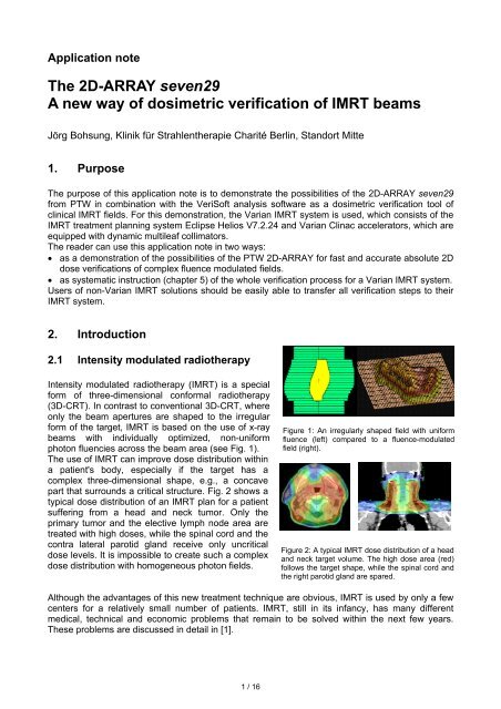
Application note<br />
<strong>The</strong> <strong>2D</strong>-<strong>ARRAY</strong> <strong>seven29</strong><br />
A <strong>new</strong> <strong>way</strong> <strong>of</strong> <strong>dosimetric</strong> <strong>verification</strong> <strong>of</strong> IMRT beams<br />
Jörg Bohsung, Klinik für Strahlentherapie Charité Berlin, Standort Mitte<br />
1. Purpose<br />
<strong>The</strong> purpose <strong>of</strong> this application note is to demonstrate the possibilities <strong>of</strong> the <strong>2D</strong>-<strong>ARRAY</strong> <strong>seven29</strong><br />
from <strong>PTW</strong> in combination with the VeriS<strong>of</strong>t analysis s<strong>of</strong>tware as a <strong>dosimetric</strong> <strong>verification</strong> tool <strong>of</strong><br />
clinical IMRT fields. For this demonstration, the Varian IMRT system is used, which consists <strong>of</strong> the<br />
IMRT treatment planning system Eclipse Helios V7.2.24 and Varian Clinac accelerators, which are<br />
equipped with dynamic multileaf collimators.<br />
<strong>The</strong> reader can use this application note in two <strong>way</strong>s:<br />
• as a demonstration <strong>of</strong> the possibilities <strong>of</strong> the <strong>PTW</strong> <strong>2D</strong>-<strong>ARRAY</strong> for fast and accurate absolute <strong>2D</strong><br />
dose <strong>verification</strong>s <strong>of</strong> complex fluence modulated fields.<br />
• as systematic instruction (chapter 5) <strong>of</strong> the whole <strong>verification</strong> process for a Varian IMRT system.<br />
Users <strong>of</strong> non-Varian IMRT solutions should be easily able to transfer all <strong>verification</strong> steps to their<br />
IMRT system.<br />
2. Introduction<br />
2.1 Intensity modulated radiotherapy<br />
Intensity modulated radiotherapy (IMRT) is a special<br />
form <strong>of</strong> three-dimensional conformal radiotherapy<br />
(3D-CRT). In contrast to conventional 3D-CRT, where<br />
only the beam apertures are shaped to the irregular<br />
form <strong>of</strong> the target, IMRT is based on the use <strong>of</strong> x-ray<br />
beams with individually optimized, non-uniform<br />
photon fluencies across the beam area (see Fig. 1).<br />
<strong>The</strong> use <strong>of</strong> IMRT can improve dose distribution within<br />
a patient's body, especially if the target has a<br />
complex three-dimensional shape, e.g., a concave<br />
part that surrounds a critical structure. Fig. 2 shows a<br />
typical dose distribution <strong>of</strong> an IMRT plan for a patient<br />
suffering from a head and neck tumor. Only the<br />
primary tumor and the elective lymph node area are<br />
treated with high doses, while the spinal cord and the<br />
contra lateral parotid gland receive only uncritical<br />
dose levels. It is impossible to create such a complex<br />
dose distribution with homogeneous photon fields.<br />
Although the advantages <strong>of</strong> this <strong>new</strong> treatment technique are obvious, IMRT is used by only a few<br />
centers for a relatively small number <strong>of</strong> patients. IMRT, still in its infancy, has many different<br />
medical, technical and economic problems that remain to be solved within the next few years.<br />
<strong>The</strong>se problems are discussed in detail in [1].<br />
1 / 16<br />
Figure 1: An irregularly shaped field with uniform<br />
fluence (left) compared to a fluence-modulated<br />
field (right).<br />
Figure 2: A typical IMRT dose distribution <strong>of</strong> a head<br />
and neck target volume. <strong>The</strong> high dose area (red)<br />
follows the target shape, while the spinal cord and<br />
the right parotid gland are spared.
2.2 IMRT delivery techniques<br />
Several IMRT delivery techniques can be found in publications (see, e.g., [1]). Today, most <strong>new</strong>ly<br />
installed IMRT delivery systems use modulated beams with fixed beam directions. <strong>The</strong> fluence<br />
modulations are created by the multileaf collimator (MLC), which runs in one <strong>of</strong> two special IMRTmodes:<br />
• <strong>The</strong> multi-segment method approximates the continuously modulated optimized fluence <strong>of</strong> each<br />
fixed field direction by a stepwise fluence distribution. This is done by combining a set <strong>of</strong> small<br />
homogeneous field segments <strong>of</strong> different weights, which are shaped by the MLC. This method<br />
is <strong>of</strong>ten also referred to as step-and-shoot delivery, because the radiation is only turned on<br />
when the leaves have reached their prescribed positions for each segment.<br />
• A technically more advanced method is the dynamic MLC technique (<strong>of</strong>ten also called sliding<br />
window method). Here the fluence pr<strong>of</strong>ile along the moving direction <strong>of</strong> a leaf pair is created by<br />
sweeping the leaf pair with different openings over the field while the beam is on all the time.<br />
Both methods result in similar final dose distributions, although the dynamic MLC approach can<br />
generate a better approximation <strong>of</strong> the optimized fluence and allows a faster delivery. On the other<br />
hand, the multi-segment method is easier to implement and needs a slightly lower number <strong>of</strong><br />
monitor units.<br />
In contrast to conventional homogeneous fields, the number <strong>of</strong> monitor units for both methods as<br />
given by the treatment planning system no longer has a simple relation to the delivered dose <strong>of</strong><br />
that field. <strong>The</strong>refore, many groups feel it necessary to verify each single treatment field<br />
<strong>dosimetric</strong>ally before its clinical use.<br />
2.3 IMRT and quality assurance<br />
IMRT is a very complex treatment modality. <strong>The</strong>refore, <strong>new</strong> quality assurance procedures must be<br />
implemented throughout the complete clinical process [1]. Here we will only discuss some<br />
technical aspects. Typically, the clinical implementation <strong>of</strong> IMRT passes through at least three<br />
steps:<br />
1. <strong>The</strong> installation and commissioning phase <strong>of</strong> the treatment planning and the delivery system<br />
2. <strong>The</strong> clinical starting phase, where each treatment is tested by an individual <strong>verification</strong><br />
procedure, which typically is extremely time-consuming and not very standardized<br />
3. <strong>The</strong> routine phase, where standardized QA procedures are used to guarantee safe and reliable<br />
IMRT deliveries for a large number <strong>of</strong> patients<br />
Most groups focus only on the first two phases. However, the third phase is by far the most critical<br />
one for a stable IMRT routine delivery. <strong>The</strong> routine use <strong>of</strong> IMRT for large patient numbers is only<br />
possible if standardized QA procedures have been carefully defined and easy-to-use measuring<br />
equipment together with user-friendly analysis s<strong>of</strong>tware is available.<br />
For both MLC modulation methods, the delivered doses have a complex, non-intuitive relationship<br />
to the number <strong>of</strong> monitor units. It is also impossible to predict the exact combination <strong>of</strong> field<br />
segments or the leaf motion patterns. <strong>The</strong>refore, all IMRT groups, which are using the MLC for the<br />
creation <strong>of</strong> fluence modulations, must establish a precise and reliable method for the <strong>dosimetric</strong><br />
<strong>verification</strong> <strong>of</strong> IMRT plans. Especially during the starting period, each plan must be <strong>dosimetric</strong>ally<br />
verified, but <strong>dosimetric</strong> <strong>verification</strong> is also recommended after s<strong>of</strong>tware upgrades or the expansion<br />
to <strong>new</strong> tumor entities.<br />
2 / 16
3. Dosimetric <strong>verification</strong> <strong>of</strong> treatment plans<br />
3.1 <strong>The</strong> phantom substitution method<br />
Because a <strong>verification</strong> <strong>of</strong> dose distributions within a real patient is not possible, the phantom<br />
substitution method is <strong>of</strong>ten used, which works as follows:<br />
• Within the treatment planning system, the patient plan is transferred - either all together or fieldby-field<br />
- to a special phantom.<br />
• <strong>The</strong> dose distribution is recalculated within that phantom without changing any <strong>dosimetric</strong>ally<br />
relevant treatment parameter.<br />
• At the treatment machine, the phantom – equipped with appropriate dosimeters – is irradiated<br />
using the IMRT fields <strong>of</strong> the real patient plan, again without changing any <strong>dosimetric</strong>ally relevant<br />
treatment parameters.<br />
• <strong>The</strong> measurements are compared against the calculated dose values.<br />
A large variety <strong>of</strong> phantoms and dosimeters are described in publications and are used clinically<br />
(see for example [2]). <strong>The</strong> phantom substitution method can be performed in two different <strong>way</strong>s,<br />
either plan-related or field-related.<br />
3.2 <strong>The</strong> plan-related approach<br />
For the plan-related approach, the whole plan (i.e., all<br />
fields with their correct beam entry directions) is<br />
transferred within the treatment planning system to a<br />
<strong>verification</strong> phantom and the dose distribution is<br />
calculated.<br />
A phantom, which is suitable for the plan-related<br />
approach typically has a cylindrical, elliptical or<br />
spherical shape and is <strong>of</strong>ten made <strong>of</strong> slabs, which<br />
allow the filling <strong>of</strong> the phantom with <strong>dosimetric</strong> films<br />
(see Fig. 3). Additionally, it is <strong>of</strong>ten possible, to equip<br />
the phantom with ion chambers for absolute point dose<br />
measurements. <strong>PTW</strong> <strong>of</strong>fers several specialized<br />
phantoms for the plan-related approach:<br />
• <strong>The</strong> cylindrical Head/Neck Verification Phantom T40015 for film dosimetry;<br />
• <strong>The</strong> Head/Neck Verification Phantom T40014, which accommodates the <strong>PTW</strong> linear array<br />
LA48;<br />
• <strong>The</strong> Matrix IMRT Verification Phantom T40026 for the use <strong>of</strong> up to 25 ion chambers, which can<br />
be individually placed throughout the entire height <strong>of</strong> the phantom.<br />
<strong>The</strong> advantages <strong>of</strong> the plan-related approach are obvious:<br />
• <strong>The</strong> entire plan can be verified within one run.<br />
• All treatment parameters including the beam entry directions are identical to the real patient<br />
treatment. <strong>The</strong>refore, also critical points <strong>of</strong> the setup such as influence <strong>of</strong> the treatment couch,<br />
etc., can be detected.<br />
• Because the complete treatment plan is verified, a connection between the measured dose<br />
distribution and the real anatomical situation can be made. It is therefore easy to decide if a<br />
detected local disagreement between calculation and measurement is nevertheless clinically<br />
acceptable or not.<br />
3 / 16<br />
Dosimetric<br />
film<br />
Phantom<br />
Hole for ion<br />
chamber<br />
Figure 3: A <strong>verification</strong> phantom for the planrelated<br />
approach. <strong>The</strong> arrows illustrate the entry<br />
directions <strong>of</strong> a typical IMRT plan.
However, the plan-related approach also has several practical disadvantages, which make its<br />
routine use difficult:<br />
• Real 3D dose measurements are extremely time consuming and not available under clinical<br />
conditions. A plan-related <strong>verification</strong> is therefore normally restricted to only a few 1D or <strong>2D</strong> cuts<br />
out <strong>of</strong> the 3D dose cube. <strong>The</strong>refore delivery problems (e.g., misaligned leafs) outside the<br />
measuring zone may not be detected.<br />
• Depending on the used measuring system, the plan-related approach may be accompanied by<br />
severe <strong>dosimetric</strong> problems. A typical example is the film calibration, which is not trivial for films,<br />
which are oriented parallel to the beam entrance direction.<br />
• Because all fields are treated at once, it is <strong>of</strong>ten difficult to locate the reason for a detected<br />
<strong>dosimetric</strong> discrepancy.<br />
• <strong>The</strong> phantom-preparation is time consuming.<br />
3.3 <strong>The</strong> field-related approach<br />
For the field-related approach, each single treatment<br />
field is transferred separately to a <strong>verification</strong> phantom.<br />
All treatment parameters are the same as for the real<br />
patient plan, except the gantry angle, which is normally<br />
set to 0° for all beams. <strong>The</strong> field-related approach<br />
requires only a very simple rectangular phantom,<br />
which is able to carry a <strong>dosimetric</strong> film or another<br />
planar dosimeter at a plane perpendicular to the beam<br />
entrance direction (see Fig. 4). Sometimes the<br />
phantom has additional holes for ion chamber<br />
measurements. <strong>PTW</strong> provides the Universal IMRT<br />
Verification Phantom T40020 for the field-related<br />
approach.<br />
<strong>The</strong> field-related approach is <strong>of</strong>ten criticized, because it does not reflect the real treatment as well<br />
as the plan-related approach. On the other hand, the field-related approach has a number <strong>of</strong><br />
advantages, which are especially valuable if IMRT is operated under routine conditions.<br />
• <strong>The</strong> <strong>verification</strong> process covers the complete modulated area <strong>of</strong> each field. All potential delivery<br />
problems are therefore safely detected.<br />
• Dose measurements are al<strong>way</strong>s performed in a plane perpendicular to the central axis; hence,<br />
<strong>dosimetric</strong> problems (e.g., film calibration) are less critical than for the plan-related approach.<br />
• A detected <strong>dosimetric</strong> discrepancy can easily be traced back to its reason, e.g., an improperly<br />
adjusted leaf.<br />
• <strong>The</strong> preparation and setup <strong>of</strong> the phantom is easy and not very time-consuming.<br />
• <strong>The</strong> field-related approach is perfectly adapted to the use <strong>of</strong> various electronic <strong>2D</strong> measuring<br />
devices such as the <strong>2D</strong>-<strong>ARRAY</strong> <strong>seven29</strong>.<br />
For groups which have either no access to film dosimetry or want to avoid it because <strong>of</strong> its<br />
complexity and cost, the latter point is an important argument in favor <strong>of</strong> the field-related approach.<br />
4 / 16<br />
Dosimetric<br />
film<br />
Phantom<br />
Hole for ion<br />
chamber<br />
Figure 4: A <strong>verification</strong> phantom for the planrelated<br />
approach.
4. <strong>The</strong> <strong>2D</strong>-<strong>ARRAY</strong> <strong>seven29</strong> and the analysis s<strong>of</strong>tware VeriS<strong>of</strong>t<br />
4.1 <strong>2D</strong>-<strong>ARRAY</strong> <strong>seven29</strong><br />
<strong>The</strong> <strong>2D</strong>-<strong>ARRAY</strong> <strong>seven29</strong> consists <strong>of</strong> a plane matrix <strong>of</strong> 27 x 27 air-filled ion chambers. <strong>The</strong> vented<br />
plane-parallel ion chambers are 5 mm x 5 mm x 5 mm in size and the center-to-center spacing is<br />
10 mm. <strong>The</strong> 729 chambers cover a maximum field size <strong>of</strong> 27 cm x 27 cm. <strong>The</strong> surrounding<br />
material is acrylic (PMMA). <strong>The</strong> package includes an interface for fast data acquisition. <strong>The</strong> display<br />
cycle can be selected between 400 and 1000 ms.<br />
<strong>The</strong> <strong>2D</strong>-<strong>ARRAY</strong> <strong>seven29</strong> allows absolute dose and dose rate measurements <strong>of</strong> high-energy<br />
photon fields. On-site calibration is not necessary.<br />
<strong>The</strong> data acquisition s<strong>of</strong>tware MatrixScan is used to acquire dose or dose rate data; it displays 3D<br />
graphics and transfers the acquired data to the s<strong>of</strong>tware packages VeriS<strong>of</strong>t, MultiCheck or<br />
MEPHYSTO.<br />
4.2 VeriS<strong>of</strong>t<br />
VeriS<strong>of</strong>t assists physicists in comparing dose distributions measured in an IMRT <strong>verification</strong><br />
phantom with dose distributions computed by a radiotherapy treatment planning system. Matrices<br />
<strong>of</strong> measured and calculated points <strong>of</strong> an IMRT beam are compared by subtracting the matrices<br />
and visualizing the result. <strong>The</strong> gamma evaluation method [3] is supported, hot and cold spots can<br />
easily be located, and the maximum and average deviation between treatment plan and measured<br />
beam is determined.<br />
VeriS<strong>of</strong>t allows to import data from various treatment planning systems.<br />
5. Dosimetric <strong>verification</strong> <strong>of</strong> IMRT fields with the <strong>2D</strong>-<strong>ARRAY</strong> -<br />
a step-by-step instruction for the Varian IMRT solution<br />
In this chapter, the field-related <strong>dosimetric</strong> <strong>verification</strong> <strong>of</strong> IMRT fields with the <strong>2D</strong>-<strong>ARRAY</strong> <strong>seven29</strong>,<br />
as it is performed at the Charité Hospital Berlin, is demonstrated systematically.<br />
5.1 <strong>The</strong> IMRT system<br />
IMRT treatment planning is done with the Eclipse Helios treatment planning system V7.2.24<br />
(Varian Medical Systems). Within Eclipse, the dynamic leaf motion instructions are calculated,<br />
which are necessary to generate the optimized fluences at the treatment machine.<br />
<strong>The</strong> modulated photon fields are delivered by Varian Clinac linear accelerators, which are<br />
equipped with different dynamic multi leaf collimators (MLC-120, MLC-80 and MLC-52).<br />
All necessary treatment parameters, i.e., monitor units, field sizes, gantry angles and leaf motion<br />
instructions, are stored in the database <strong>of</strong> the record-and-verify system VARiS Vision 6.2 and<br />
provided for patient treatment. In Berlin, we perform not only patient treatments but also all IMRT<br />
<strong>verification</strong>s under the control <strong>of</strong> VARiS Vision.<br />
5 / 16
5.2 Phantom setup, CT scanning and preparation within Eclipse<br />
For the field-related <strong>verification</strong> process, no special phantom is necessary; it is convenient to<br />
arrange the array between plates <strong>of</strong> water equivalent material. We use a sandwich setup <strong>of</strong> water<br />
equivalent <strong>PTW</strong> RW3 plates with a stack <strong>of</strong> 3 cm below and 5 cm above the array (see Fig. 5).<br />
<strong>The</strong> phantom arrangement is CT scanned then in exactly the same <strong>way</strong> as it is later used for the<br />
<strong>verification</strong> measurements. To achieve an adequate spatial resolution during the following<br />
<strong>verification</strong> dose calculations, it is essential to scan the phantom with a sufficiently small slice<br />
thickness. We have scanned the phantom with a slice thickness <strong>of</strong> 2 mm (Fig. 6). <strong>The</strong> scanned<br />
phantom is imported via DICOM to Eclipse. Directly after import, it is convenient to define a user<br />
origin within Eclipse exactly at the effective measuring point <strong>of</strong> the central ion chamber <strong>of</strong> the<br />
array.<br />
<strong>2D</strong> array<br />
RW3<br />
Figure 5: For the field-related <strong>verification</strong> the <strong>2D</strong>-<br />
<strong>ARRAY</strong> is simply located between RW3 plates. 3 cm<br />
RW3 material are below, 5 cm above the array.<br />
<strong>The</strong> effective measuring point is located in the middle <strong>of</strong> the chamber area and 5 mm below the<br />
surface <strong>of</strong> the <strong>2D</strong>-<strong>ARRAY</strong>. By that, all fields, which are verified afterwards, are automatically<br />
positioned correctly with their isocenter at the effective measuring point <strong>of</strong> the central ion chamber.<br />
Note that it is necessary to perform the scanning and import process only once. Within Eclipse, the<br />
phantom with the correctly placed user origin can then be defined as the default phantom, which is<br />
al<strong>way</strong>s used for <strong>verification</strong>.<br />
5.3 Transfer <strong>of</strong> the patient treatment fields and dose calculation<br />
Eclipse supports both the plan-related and the field-related approach for the <strong>verification</strong> <strong>of</strong> IMRT<br />
plans. After an IMRT plan is accepted for treatment, the planner has to use the function “create<br />
<strong>verification</strong> plan”, to start the <strong>verification</strong> process. Here, the user can select between several<br />
possibilities (Fig. 7). For the field-related approach with the <strong>2D</strong>-<strong>ARRAY</strong>, the following selections<br />
are necessary (Fig. 7a):<br />
• Each patient field must be placed into separate <strong>verification</strong> plans<br />
• <strong>The</strong> couch, gantry and collimator angles must be reset to 0°<br />
<strong>The</strong>n the <strong>verification</strong> method has to be defined (Fig. 7b), which is “Phantom” in our case. <strong>The</strong> user<br />
can then select the correct <strong>verification</strong> phantom, which then can be set as default.<br />
6 / 16<br />
Figure 6: <strong>The</strong> scanned phantom arrangement<br />
after import to Eclipse. <strong>The</strong> phantom was<br />
scanned with 2 mm slice thickness. <strong>The</strong> user<br />
origin is marked by a red cross.
a b<br />
Figure 7: Creation <strong>of</strong> the <strong>verification</strong> plan (both plan- and field-related) within Eclipse. <strong>The</strong> correct options for the fieldrelated<br />
approach with the <strong>2D</strong>-<strong>ARRAY</strong> are selected.<br />
For each field <strong>of</strong> the patient plan, a <strong>new</strong> <strong>verification</strong><br />
plan is now created. <strong>The</strong> field isocenters are<br />
automatically positioned at the correct place if the<br />
user origin was properly defined (see 5.2). <strong>The</strong><br />
created <strong>verification</strong> fields have exactly the same<br />
<strong>dosimetric</strong>ally relevant treatment parameters as the<br />
real patient fields. Any changes are suspended by<br />
Eclipse. Thus, it is guaranteed that the <strong>verification</strong><br />
fields really reflect the behavior <strong>of</strong> the real patient<br />
treatments.<br />
After the correct transfer <strong>of</strong> the treatment fields to the<br />
<strong>verification</strong> phantom, the planner can calculate the<br />
3D dose distribution <strong>of</strong> each field. In Fig. 8, the dose<br />
distribution <strong>of</strong> an IMRT field <strong>of</strong> a complex head and<br />
neck treatment plan within the <strong>verification</strong> phantom<br />
is depicted. Note that the frontal view already shows<br />
the <strong>2D</strong> dose distribution within the effective<br />
measuring plane <strong>of</strong> the <strong>2D</strong>-<strong>ARRAY</strong>.<br />
5.4 Export <strong>of</strong> the <strong>verification</strong> dose plane<br />
<strong>The</strong> dose comparison in VeriS<strong>of</strong>t requires a DICOM dose export <strong>of</strong> the <strong>2D</strong> dose distribution within<br />
the effective measuring plane <strong>of</strong> the ion chambers. To do that, the following steps are necessary:<br />
• <strong>The</strong> frontal dose view in Eclipse must be adjusted in such a <strong>way</strong> that it shows the correct<br />
measuring plane. If the user origin was defined as discussed in section 5.2, the y-coordinate <strong>of</strong><br />
that plane is y=0.<br />
• <strong>The</strong> frontal dose view must have the focus. <strong>The</strong> easiest <strong>way</strong> to guarantee for that is to enlarge<br />
the frontal dose view (Fig. 9a).<br />
• <strong>The</strong> plane export is started by a right-click (Fig. 9a).<br />
• Within the dose export wizard, the “absolute” dose export must be selected and the dimensions<br />
<strong>of</strong> the dose plane must be correctly set (Fig. 9b).<br />
<strong>The</strong> Eclipse dose export wizard automatically positions the center <strong>of</strong> the exported dose matrix at<br />
the field isocenter (see Fig. 9b). This function is important for the later dose comparison within<br />
VeriS<strong>of</strong>t as discussed in section 5.7 and was not available in earlier Eclipse versions.<br />
To avoid confusion with the cryptic DICOM file names, it is convenient to save all DICOM plane<br />
dose files within a special folder, which is given the patient’s name, for example.<br />
7 / 16<br />
Figure 8: Dose distribution <strong>of</strong> an IMRT field within the<br />
<strong>verification</strong> phantom. <strong>The</strong> <strong>dosimetric</strong>ally relevant<br />
treatment parameters are identical to the patient plan<br />
and cannot be changed by the user.
a b<br />
Figure 9: DICOM export <strong>of</strong> the correct dose plane with y=0. Note, that the center <strong>of</strong> the exported dose matrix is<br />
automatically positioned at the isocenter.<br />
5.5 Phantom setup and calibration measurement<br />
<strong>The</strong> Phantom setup for the measurements is shown in Fig. 10. <strong>The</strong> gantry and collimator angles<br />
are set to 0°. <strong>The</strong> <strong>2D</strong>-<strong>ARRAY</strong> is located on top <strong>of</strong> a package <strong>of</strong> 3 cm RW3 material and adjusted in<br />
a <strong>way</strong> that the isocenter is positioned at the effective measuring point <strong>of</strong> the central ion chamber,<br />
i.e., 5 mm below the front plate <strong>of</strong> the array (Fig. 10a). <strong>The</strong>n another stack <strong>of</strong> 5 cm RW3 material is<br />
added above the array (Fig. 10b). Finally, the SSD <strong>of</strong> this arrangement should be 94.5 cm.<br />
a<br />
Figure 10: Phantom setup for the <strong>verification</strong> measurements. <strong>The</strong> isocenter is adjusted to the effective measuring point<br />
<strong>of</strong> the central ion chamber <strong>of</strong> the <strong>2D</strong>-<strong>ARRAY</strong>.<br />
Although the <strong>2D</strong>-<strong>ARRAY</strong> is already calibrated in absorbed dose to water, normally each<br />
measurement must be corrected for different air pressure and temperature, for the used photon<br />
quality and for possible non-water equivalent properties <strong>of</strong> the phantom. To avoid these<br />
corrections, which are time-consuming and susceptible to errors, we use a simple calibration field<br />
with a known dose, which is delivered before each <strong>verification</strong> measurement:<br />
• Within the treatment planning system, a simple “calibration plan” with only one homogeneous<br />
field with a field size <strong>of</strong> 10x10 cm 2 and a gantry angle <strong>of</strong> 0° is created. Beam quality and<br />
isocenter position are identical to those <strong>of</strong> the IMRT fields.<br />
• <strong>The</strong> monitor units <strong>of</strong> that field are adjusted to an isocenter dose Dcal <strong>of</strong> e.g., 2.00 Gy.<br />
• After positioning <strong>of</strong> the phantom (Fig. 10), this calibration field is al<strong>way</strong>s treated as the first field<br />
<strong>of</strong> a <strong>verification</strong> session and the dose is measured with the <strong>2D</strong>-<strong>ARRAY</strong> using MatrixScan.<br />
8 / 16<br />
b
• <strong>The</strong> readout M <strong>of</strong> the central chamber is noted. This chamber can be selected in the “options”<br />
menu <strong>of</strong> MatrixScan (chamber coordinates [14,14]). <strong>The</strong> dose is then visible at the status bar <strong>of</strong><br />
MatrixScan.<br />
• A calibration factor f = Dcal/M is calculated, which is used for the correction <strong>of</strong> all later <strong>verification</strong><br />
measurements (see Section 5.7).<br />
This calibration method has the additional advantage that it also corrects for possible deviations in<br />
the output calibration <strong>of</strong> the linear accelerator.<br />
5.6 Verification measurements<br />
In Berlin, all <strong>verification</strong> measurements are<br />
performed in the clinical mode under the control<br />
<strong>of</strong> VARiS Vision. <strong>The</strong> <strong>verification</strong> fields are<br />
prepared within VARiS Vision in its own<br />
treatment course, which is linked to the patient<br />
for whom the <strong>verification</strong> is performed. Unlike the<br />
real treatment fields, however, the <strong>verification</strong><br />
fields do not add up any dose to the patient<br />
within VARiS Vision.<br />
Immediately after the delivery <strong>of</strong> the calibration<br />
field (see section 5.5), the IMRT fields are<br />
irradiated one after the other and measured with<br />
the acquisition s<strong>of</strong>tware MatrixScan. In Fig. 11, a<br />
screenshot <strong>of</strong> MatrixScan during the<br />
measurement <strong>of</strong> an IMRT field is depicted.<br />
To block as little machine time as possible, only<br />
the raw data are saved and no further corrections are performed during the measurements. If the<br />
calculated DICOM dose plane data were already saved in a special patient folder as proposed in<br />
section 5.4, it makes sense to store the measurements within the same folder.<br />
5.7 Analysis <strong>of</strong> the measurements using VeriS<strong>of</strong>t and documentation <strong>of</strong> the<br />
results<br />
To guarantee a smooth and fast data analysis process,<br />
we suggest using the following procedure for each<br />
calculated and measured field pair:<br />
• <strong>The</strong> calculated data set is read into matrix A. For<br />
small fields, it is worth defining an appropriate region<br />
<strong>of</strong> interest to avoid too many data points outside the<br />
interesting area.<br />
• <strong>The</strong> corresponding measured data set is read into<br />
matrix B.<br />
• <strong>The</strong> measured data set is calibrated by pushing the<br />
“Calibrate” button. Within the calibration window<br />
(Fig. 12), the measured data set is now multiplied by<br />
the determined correction factor f = Dcal/M with<br />
Dcal = 2.00 Gy (see section 5.5).<br />
In the example shown in Fig. 12, the measured central chamber dose M <strong>of</strong> the calibration field<br />
was M = 2.02 Gy.<br />
9 / 16<br />
Figure 11: Screen shot <strong>of</strong> MatrixScan during<br />
a measurement <strong>of</strong> an IMRT field.<br />
Figure 12: Calibration procedure. In this<br />
example, the measured data set is<br />
corrected by a factor 2.00/2.02 = 0.99.
• By default, VeriS<strong>of</strong>t normalizes each matrix individually to its maximum dose. This is not<br />
meaningful for absolute dose measurements with the <strong>2D</strong>-<strong>ARRAY</strong>. <strong>The</strong>refore, both data sets<br />
have to be normalized to the same meaningful value (e.g., the dose at the isocenter).<br />
• <strong>The</strong> correct positioning <strong>of</strong> the two data sets is checked using the “Pr<strong>of</strong>iles” option. Normally, no<br />
alignment should be required. However, positional corrections <strong>of</strong> ±1 mm in both x and y<br />
directions are sometimes necessary due to slight misalignments <strong>of</strong> the phantom during the<br />
measurements.<br />
Fig. 13a shows the isodose overlay, which already gives a first impression <strong>of</strong> the concurrence <strong>of</strong><br />
the two data sets. This concurrence is quantitatively confirmed by vertical and horizontal line scans<br />
through the isocenter (Fig. 13b).<br />
Line scans have the disadvantage that an investigation <strong>of</strong> the complete area is quite timeconsuming.<br />
<strong>The</strong>refore, VeriS<strong>of</strong>t provides additional quantitative <strong>2D</strong> compare modes.<br />
Figure 13a: VeriS<strong>of</strong>t isodose overlay <strong>of</strong> a typical IMRT<br />
head and neck field. <strong>The</strong> measured isodoses are depicted<br />
as dotted lines.<br />
In Fig. 14, a difference plot is shown, where each measured chamber dose Dm(i,j) is compared to<br />
the averaged calculated dose according to the following formula:<br />
∆D(<br />
i,<br />
j)<br />
D<br />
D<br />
=<br />
m<br />
( i,<br />
j)<br />
D<br />
−<br />
c<br />
D<br />
c<br />
( i,<br />
j)<br />
( i,<br />
j)<br />
* 100%<br />
Note that VeriS<strong>of</strong>t provides also a percentage difference mode, which is relative to the<br />
normalization dose <strong>of</strong> matrix A. This mode however is not as sensitive to the low dose.<br />
10 / 16<br />
Figure 13b: Horizontal (above) and vertical (below)<br />
line scans through the isocenter <strong>of</strong> the IMRT field <strong>of</strong> Fig. 13a.<br />
Calculations are shown as blue lines and the measured<br />
chamber values are depicted as green bars.
a<br />
Figure 14: Difference plot <strong>of</strong> the dose distribution <strong>of</strong><br />
Fig. 13a. Most differences are below 3% <strong>of</strong> the local<br />
measured dose. Higher deviations are only found at highgradient<br />
regions and at very low doses.<br />
While dose difference plots work very good within low-gradient areas <strong>of</strong> the analyzed dose<br />
distribution, they may show artificially large deviations in high-gradient parts (Fig. 14). To overcome<br />
that problem, which is especially critical for highly modulated IMRT fields, Low et al. developed the<br />
gamma analysis method [3]. <strong>The</strong> gamma method judges the concurrence <strong>of</strong> <strong>2D</strong> dose distributions<br />
using two criteria: the local dose difference within low-gradient areas and the distance-toagreement<br />
(i.e., the distance <strong>of</strong> two points, which have the same dose). <strong>The</strong> user has to define two<br />
acceptance values: <strong>The</strong> maximum acceptable local dose difference (in %) and the maximum<br />
acceptable distance to concurrence (in mm). In VeriS<strong>of</strong>t, the gamma method is implemented<br />
according to the method <strong>of</strong> Depuydt et al. [4], which adapts the Low algorithm to the use <strong>of</strong> discrete<br />
data sets. For our analyses, we use al<strong>way</strong>s 3% dose difference and 2 mm distance to agreement.<br />
Calculated dose value are not analyzed for dose values below 5% <strong>of</strong> the maximum.<br />
Fig. 15 shows the resulting gamma evaluation. <strong>The</strong> acceptance criteria are not met for only a few<br />
points below the 10% isodose. This is a typical result. Two factors are responsible for higher<br />
deviations with very low doses:<br />
• <strong>The</strong> measuring device has a higher relative measuring error.<br />
• For very low doses, the dose <strong>of</strong> a dynamically collimated IMRT field is mainly determined by leaf<br />
transmission, which is not calculated as precise as the dose within the open part <strong>of</strong> the field by<br />
the treatment planning system.<br />
We normally accept these dose deviations, if they only show up in low dose areas. In chapter 6,<br />
more <strong>verification</strong> examples <strong>of</strong> IMRT fields are discussed<br />
11 / 16<br />
Figure 15: Gamma index plot <strong>of</strong> the dose distribution <strong>of</strong><br />
Fig. 13a. <strong>The</strong> red dots indicate points where the<br />
acceptance criteria (3%, 3 mm) are not reached. All<br />
these points are located within low-dose regions.
Fig. 16 finally shows the printout <strong>of</strong> the IMRT field, as it is provided by VeriS<strong>of</strong>t and as we use it for<br />
documentation.<br />
5.8 Time requirement<br />
Figure 16: Documentation <strong>of</strong> the result<br />
<strong>The</strong> <strong>verification</strong> process with the <strong>2D</strong>-<strong>ARRAY</strong> <strong>seven29</strong> is highly standardized. <strong>The</strong>refore, the entire<br />
procedure can be performed within an acceptable time. In Tab. 1, the time requirements for the<br />
different <strong>verification</strong> steps for a five-field IMRT plan are collected.<br />
Future versions <strong>of</strong> VeriS<strong>of</strong>t will allow an even more automated data analysis, so that a further time<br />
reduction can be expected.<br />
Procedure Section Average time<br />
[min]<br />
Transfer <strong>of</strong> the patient treatment fields and dose calculation 5.3 10<br />
Export <strong>of</strong> the <strong>verification</strong> dose plane 5.4 5<br />
Verification measurements including setup 5.5 25<br />
Analysis <strong>of</strong> the measurements with VeriS<strong>of</strong>t 5.6 20<br />
Total 60<br />
Table 1: Time requirement for the different steps <strong>of</strong> the <strong>verification</strong> procedure.<br />
<strong>The</strong> time requirement listed above is for the <strong>verification</strong> process with the <strong>2D</strong>-<strong>ARRAY</strong> <strong>of</strong> one patient<br />
plan. However, if plans <strong>of</strong> more than one patient have to be verified, the same hardware setup for<br />
the measurements is used, resulting in time savings. <strong>The</strong> <strong>verification</strong> process itself is also more<br />
efficient if all fields <strong>of</strong> all patients are checked against the plans in one session.<br />
12 / 16
6. Some clinical examples<br />
In Berlin, we use IMRT as a routine treatment option mainly for treatments <strong>of</strong> the prostate, head<br />
and neck tumors and for irradiations <strong>of</strong> the breast if the internal mammary lymph node chain has to<br />
be included into the target volume. In the next sections, some examples <strong>of</strong> real patient IMRT plans<br />
and their <strong>verification</strong>s are shown.<br />
6.1 Prostate<br />
For prostate IMRT treatments we use a simultaneous<br />
integrated boost (SIB) technique, where two different doses<br />
are simultaneously delivered to different parts <strong>of</strong> the target<br />
volume. <strong>The</strong> SIB technique provides two advantages:<br />
Firstly, it allows an increased dose within a specific target<br />
region (e.g., prostate) and a reduced dose to the peripheral<br />
region (e.g., periprostatic area). Secondly, it keeps the<br />
overall treatment time constant while increasing the target<br />
dose. For our patients, the CTV is irradiated with a single<br />
dose <strong>of</strong> 2.0 Gy per fraction whereas the PTV is treated<br />
simultaneously with 1.8 Gy. In Fig. 17, a five-field IMRT SIB<br />
treatment plan for a prostate patient is shown. With the SIB<br />
technique, we are able to increase the therapeutic dose<br />
safely up to 82.0 Gy without increasing the doses to the<br />
organs at risk, especially the rectum [5].<br />
In Fig. 18 the isodose overlays and gamma distributions for all five prostate IMRT fields <strong>of</strong> the<br />
treatment plan <strong>of</strong> Fig. 17 are put together. Typically, prostate IMRT fields are not modulated very<br />
much. <strong>The</strong>refore, no critical areas are normally found during the <strong>verification</strong>s.<br />
13 / 16<br />
Figure 17: Dose distribution <strong>of</strong> an IMRT SIB<br />
prostate treatment plan with five fields.<br />
Field 1 Field 2 Field 3 Field 4 Field 5<br />
Figure 18: Isodose overlays and gamma distributions <strong>of</strong> all five IMRT fields <strong>of</strong> a prostate treatment plan (measured<br />
isodose lines are dotted). Nearly all gamma values are < 1 in all fields.
6.2 Head and neck<br />
For postoperative head and neck patients, we also use an SIB IMRT technique with seven<br />
treatment fields. <strong>The</strong> former tumor volume is irradiated simultaneously with a higher dose level<br />
than the elective lymph nodes. <strong>The</strong> spinal cord and the contralateral parotid gland are spared. An<br />
example for a head and neck treatment plan was already shown in Fig. 2.<br />
<strong>The</strong> <strong>verification</strong> results for all seven fields <strong>of</strong> that plan are depicted in Fig. 19. As already discussed<br />
in Section 5.7, it is normal for such highly modulated fields that some small areas within the lowdose<br />
part <strong>of</strong> the dose distributions show gamma values >1.<br />
Field 1 Field 2 Field 3 Field 4<br />
Field 5<br />
Field 6<br />
Figure 19: Isodose overlays and gamma distributions <strong>of</strong> all seven IMRT fields <strong>of</strong> a head and neck treatment plan (measured<br />
isodose lines are dotted). Because <strong>of</strong> the more complex modulation, some gamma values within the low-dose regions are<br />
>1 (see discussion in Section 5.7).<br />
14 / 16<br />
Field 7
6.3 Breast<br />
<strong>The</strong> gain <strong>of</strong> IMRT for breast treatments is not as<br />
clear as for the other discussed tumor sites. If<br />
the breast alone is the target volume,<br />
conventional dose distributions cannot be<br />
improved very much by IMRT. However, if the<br />
internal mammary lymph node chain has to be<br />
included, the target volume is concavely shaped<br />
around the chest wall and all conventional<br />
techniques suffer from a quite high dose burden<br />
to the ipsilateral lung. For this special case,<br />
IMRT can improve the conformity <strong>of</strong> the dose<br />
distribution. Fig. 20 shows a typical seven field<br />
IMRT plan for a breast treatment with included<br />
internal mammary lymph node chain.<br />
15 / 16<br />
Figure 20: Axial and frontal dose distribution <strong>of</strong> a<br />
breast IMRT with included internal mammary lymph<br />
node chain.<br />
Field 1 Field 2 Field 3 Field 4<br />
Field 5<br />
Field 6<br />
Figure 21: Isodose overlays and gamma distributions <strong>of</strong> all seven IMRT fields <strong>of</strong> a breast treatment with included internal<br />
mammary chain (measured isodose lines are dotted). Because <strong>of</strong> the extremely complex modulation, some gamma values<br />
within the low-dose regions are >1 (see discussion in Section 5.7).<br />
Field 7
Fig. 21 shows again the <strong>verification</strong> results. <strong>The</strong> typical fields <strong>of</strong> breast IMRT plans are extremely<br />
modulated with large central low-dose areas to spare the lung. <strong>The</strong>refore, some parts <strong>of</strong> gamma<br />
>1 have to be accepted again. Note that the spatial resolution <strong>of</strong> the <strong>2D</strong>-<strong>ARRAY</strong> <strong>seven29</strong> is good<br />
enough, even for such highly modulated IMRT fields.<br />
7. Conclusion<br />
<strong>The</strong> <strong>2D</strong>-<strong>ARRAY</strong> <strong>seven29</strong> is a very reliable tool for the fast and precise <strong>verification</strong> <strong>of</strong> IMRT fields.<br />
Together with the analysis s<strong>of</strong>tware VeriS<strong>of</strong>t, even complex IMRT treatment plans can be verified<br />
and documented within approximately one hour. Because air-filled ion chambers are used, no<br />
complicated calibration procedures are necessary; the system is al<strong>way</strong>s ready for high-precision<br />
measurements. <strong>The</strong> effective spatial resolution <strong>of</strong> the <strong>2D</strong>-<strong>ARRAY</strong> is sufficiently high to obtain<br />
reliable results even for highly modulated IMRT fields.<br />
<strong>The</strong> <strong>dosimetric</strong> <strong>verification</strong> <strong>of</strong> IMRT fields is an important part <strong>of</strong> the routine quality assurance<br />
package for IMRT treatments. <strong>The</strong> <strong>2D</strong>-<strong>ARRAY</strong> and VeriS<strong>of</strong>t provide a reliable and easy-to-use tool<br />
for that purpose.<br />
Additionally the <strong>2D</strong>-<strong>ARRAY</strong>, in combination with the s<strong>of</strong>tware MultiCheck, can be used for daily<br />
check <strong>of</strong> the constancy <strong>of</strong> main beam parameters <strong>of</strong> the linear accelerator.<br />
8. Literature<br />
[1] Intensity Modulated Radiation Collaborative Working Group, Intensity-modulated<br />
radiotherapy: current status and issues <strong>of</strong> interest. Int. J. Radiation Oncology Biol. Phys.<br />
51: 880-914 (2001).<br />
[2] Van Esch A., Bohsung J., Sorvari P., Tenhunen M., Paiusco M., Iori M., Engström P,<br />
Nyström H, Huyskens D. Acceptance tests and quality control (QC) procedures for the<br />
clinical implementation <strong>of</strong> intensity modulated radiotherapy (IMRT) using inverse<br />
planning and the sliding window technique: experience from five radiotherapy<br />
departments. Radiother. Oncol. 65 (2002) 53-70.<br />
[3] Low, D., Harms, W., Mutic, S., Purdy, J. A technique for the quantitative evaluation <strong>of</strong><br />
dose distributions, Med. Phys. 25 (1998) 656-661.<br />
[4] Depuydt, T., Van Esch, A., Huyskens, D. A quantitative evaluation <strong>of</strong> IMRT dose<br />
distributions: refinement and clinical assessment <strong>of</strong> the gamma evaluation. Radiother.<br />
Oncol. 62 (2002) 309-319.<br />
[5] Böhmer, D., Bohsung, J., Eichwurzel, I., Moys, A., Budach, V. Clinical and physical<br />
quality assurance for intensity modulated radiotherapy <strong>of</strong> prostate cancer. Radiother.<br />
Oncol. 71 (2004) 319-325.<br />
Text and pictures by courtesy <strong>of</strong><br />
Dr. Jörg Bohsung<br />
Charité Universitätsklinikum<br />
Schumannstr. 20/21<br />
10117 Berlin<br />
D742.208.0/0 2004-06<br />
16 / 16<br />
Reprint by <strong>PTW</strong>-Freiburg<br />
Lörracher Straße 7<br />
79115 Freiburg, Germany<br />
Phone: +49 761 490 55-0<br />
info@ptw.de<br />
Eclipse, Helios, and Millennium are trademarks <strong>of</strong> Varian Medical Systems, Inc.<br />
CadPlan, Clinac, Varian, Varian Medical Systems, and VARiS are registered trademarks <strong>of</strong> Varian Medical Systems, Inc.<br />
VeriS<strong>of</strong>t and MEPHYSTO are registered trademarks <strong>of</strong> <strong>PTW</strong>-Freiburg<br />
All rights reserved. Reproduction, translation, micr<strong>of</strong>ilming as well as storage and processing in electronic systems are<br />
copyrighted. Reprinting requires the written approval <strong>of</strong> the author.