The 2D-ARRAY seven29 A new way of dosimetric verification of - PTW
The 2D-ARRAY seven29 A new way of dosimetric verification of - PTW
The 2D-ARRAY seven29 A new way of dosimetric verification of - PTW

Create successful ePaper yourself
Turn your PDF publications into a flip-book with our unique Google optimized e-Paper software.
5.2 Phantom setup, CT scanning and preparation within Eclipse<br />
For the field-related <strong>verification</strong> process, no special phantom is necessary; it is convenient to<br />
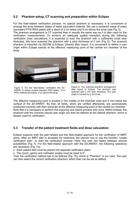
arrange the array between plates <strong>of</strong> water equivalent material. We use a sandwich setup <strong>of</strong> water<br />
equivalent <strong>PTW</strong> RW3 plates with a stack <strong>of</strong> 3 cm below and 5 cm above the array (see Fig. 5).<br />
<strong>The</strong> phantom arrangement is CT scanned then in exactly the same <strong>way</strong> as it is later used for the<br />
<strong>verification</strong> measurements. To achieve an adequate spatial resolution during the following<br />
<strong>verification</strong> dose calculations, it is essential to scan the phantom with a sufficiently small slice<br />
thickness. We have scanned the phantom with a slice thickness <strong>of</strong> 2 mm (Fig. 6). <strong>The</strong> scanned<br />
phantom is imported via DICOM to Eclipse. Directly after import, it is convenient to define a user<br />
origin within Eclipse exactly at the effective measuring point <strong>of</strong> the central ion chamber <strong>of</strong> the<br />
array.<br />
<strong>2D</strong> array<br />
RW3<br />
Figure 5: For the field-related <strong>verification</strong> the <strong>2D</strong>-<br />
<strong>ARRAY</strong> is simply located between RW3 plates. 3 cm<br />
RW3 material are below, 5 cm above the array.<br />
<strong>The</strong> effective measuring point is located in the middle <strong>of</strong> the chamber area and 5 mm below the<br />
surface <strong>of</strong> the <strong>2D</strong>-<strong>ARRAY</strong>. By that, all fields, which are verified afterwards, are automatically<br />
positioned correctly with their isocenter at the effective measuring point <strong>of</strong> the central ion chamber.<br />
Note that it is necessary to perform the scanning and import process only once. Within Eclipse, the<br />
phantom with the correctly placed user origin can then be defined as the default phantom, which is<br />
al<strong>way</strong>s used for <strong>verification</strong>.<br />
5.3 Transfer <strong>of</strong> the patient treatment fields and dose calculation<br />
Eclipse supports both the plan-related and the field-related approach for the <strong>verification</strong> <strong>of</strong> IMRT<br />
plans. After an IMRT plan is accepted for treatment, the planner has to use the function “create<br />
<strong>verification</strong> plan”, to start the <strong>verification</strong> process. Here, the user can select between several<br />
possibilities (Fig. 7). For the field-related approach with the <strong>2D</strong>-<strong>ARRAY</strong>, the following selections<br />
are necessary (Fig. 7a):<br />
• Each patient field must be placed into separate <strong>verification</strong> plans<br />
• <strong>The</strong> couch, gantry and collimator angles must be reset to 0°<br />
<strong>The</strong>n the <strong>verification</strong> method has to be defined (Fig. 7b), which is “Phantom” in our case. <strong>The</strong> user<br />
can then select the correct <strong>verification</strong> phantom, which then can be set as default.<br />
6 / 16<br />
Figure 6: <strong>The</strong> scanned phantom arrangement<br />
after import to Eclipse. <strong>The</strong> phantom was<br />
scanned with 2 mm slice thickness. <strong>The</strong> user<br />
origin is marked by a red cross.