3100A CANOBD2 Code Reader (E).qxd - Innova
3100A CANOBD2 Code Reader (E).qxd - Innova
3100A CANOBD2 Code Reader (E).qxd - Innova

You also want an ePaper? Increase the reach of your titles
YUMPU automatically turns print PDFs into web optimized ePapers that Google loves.
GGMM
Table of ContentsTitlePage No.INTRODUCTIONWhat is OBD? . . . . . . . . . . . . . . . . . . . . . . . . . . . . . . . . . . . . . 1YOU CAN DO IT! . . . . . . . . . . . . . . . . . . . . . . . . . . . . . . . . . . . . . . . 2SAFETY PRECAUTIONSSafety First! . . . . . . . . . . . . . . . . . . . . . . . . . . . . . . . . . . . . . . 3ABOUT THE CODE READERVehicles Covered . . . . . . . . . . . . . . . . . . . . . . . . . . . . . . . . . . 5Battery Replacement . . . . . . . . . . . . . . . . . . . . . . . . . . . . . . . 6Adjustments/Settings and DTC Library . . . . . . . . . . . . . . . . . . . 6CODE READER CONTROLSControls and Indicators . . . . . . . . . . . . . . . . . . . . . . . . . . . . . . 10Display Functions . . . . . . . . . . . . . . . . . . . . . . . . . . . . . . . . . . . 12PREPARATION FOR TESTINGPreliminary Vehicle Diagnosis Worksheet . . . . . . . . . . . . . . . . 14Before You Begin . . . . . . . . . . . . . . . . . . . . . . . . . . . . . . . . . . 17USING THE CODE READER<strong>Code</strong> Retrieval Procedure . . . . . . . . . . . . . . . . . . . . . . . . . . . . 19Erasing Diagnostic Trouble <strong>Code</strong>s (DTCs) . . . . . . . . . . . . . . . . 25I/M Readiness Testing . . . . . . . . . . . . . . . . . . . . . . . . . . . . . . . 27ONBOARD DIAGNOSTICSComputer Engine Controls . . . . . . . . . . . . . . . . . . . . . . . . . . . 33Diagnostic Trouble <strong>Code</strong>s (DTCs) . . . . . . . . . . . . . . . . . . . . . . 39OBD 2 Monitors . . . . . . . . . . . . . . . . . . . . . . . . . . . . . . . . . . . 42GLOSSARYGlossary of Terms and Abbreviations . . . . . . . . . . . . . . . . . . . 49WARRANTY AND SERVICINGLimited One Year Warranty . . . . . . . . . . . . . . . . . . . . . . . . . . . 51Service Procedures . . . . . . . . . . . . . . . . . . . . . . . . . . . . . . . . 51iOBD2
WHAT IS OBD?IntroductionWHAT IS OBD?The OBD2 <strong>Code</strong> <strong>Reader</strong> is designed to work on all OBD 2 compliantvehicles. All 1996 and newer vehicles (cars, light trucksand SUVs) sold in the United States are OBD 2 compliant.One of the most exciting improvementsin the automobile industry was the additionof on-board diagnostics (OBD) on vehicles,or in more basic terms, the computer thatactivates the vehicle’s “CHECK ENGINE”light. OBD 1 was designed to monitor manufacturer-specificsystems on vehicles builtfrom 1981 to 1995. Then came the developmentof OBD 2, which is on all 1996 cars and light trucks sold in theU.S. Like its predecessor, OBD 2 was adopted as part of a governmentmandate to lower vehicle emissions. But what makes OBD 2 unique isits universal application for all late model cars and trucks - domesticand import. This sophisticated program in the vehicle’s main computersystem is designed to detect failures in a range of systems, and canbe accessed through a universal OBD 2 port, which is usually foundunder the dashboard. For all OBD systems, if a problem is found, thecomputer turns on the “CHECK ENGINE” light to warn the driver, andsets a Diagnostic Trouble <strong>Code</strong> (DTC) to identify where the problemoccurred. A special diagnostic tool, such as the OBD2 <strong>Code</strong> <strong>Reader</strong>,is required to retrieve these codes, which consumers and professionalsuse as a starting point for repairs.To learn more about vehicle Computer Control Systems andOBD 2, see COMPUTER ENGINE CONTROLS on page 33.OBD2 1
You Can Do It!EASY TO USE - EASY TO VIEW - EASY TO DEFINEEasy To Use . . . .■■■■Connect the <strong>Code</strong> <strong>Reader</strong> to thevehicle’s test connector.Turn the ignition key "On.”DO NOT start the engine.<strong>Code</strong> <strong>Reader</strong> turns “On” and links automatically.Easy To View . . . .■■The <strong>Code</strong> <strong>Reader</strong> retrieves storedcodes, Freeze Frame Data and I/MReadiness status.<strong>Code</strong>s, I/M Readiness status andFreeze Frame data are displayed on the<strong>Code</strong> <strong>Reader</strong>’s LCD display. Systemstatus is indicated by LED indicators.Easy To Define . . . .■■Read code definitions from the <strong>Code</strong><strong>Reader</strong>’s LCD display.View Freeze Frame data.2 OBD2
SAFETY FIRST!Safety PrecautionsSAFETY FIRST!To avoid personal injury, instrument damage and/ordamage to your vehicle; do not use the OBD2 <strong>Code</strong> <strong>Reader</strong>before reading this manual.This manual describes common test procedures used byexperienced service technicians. Many test proceduresrequire precautions to avoid accidents that can result inpersonal injury, and/or damage to your vehicle or testequipment. Always read your vehicle's service manual andfollow its safety precautions before and during any test orservice procedure. ALWAYS observe the following generalsafety precautions:When an engine is running, it produces carbon monoxide,a toxic and poisonous gas. To prevent serious injuryor death from carbon monoxide poisoning, operate thevehicle ONLY in a well-ventilated area.To protect your eyes from propelled objects as well ashot or caustic liquids, always wear approved safetyeye protection.When an engine is running, many parts (such as thecoolant fan, pulleys, fan belt etc.) turn at high speed. Toavoid serious injury, always be aware of moving parts.Keep a safe distance from these parts as well as otherpotentially moving objects.Engine parts become very hot when the engine is running.To prevent severe burns, avoid contact with hotengine parts.PRNDLBefore starting an engine for testing or trouble-shooting,make sure the parking brake is engaged. Put thetransmission in park (for automatic transmission) orneutral (for manual transmission). Block the drivewheels with suitable blocks.Connecting or disconnecting test equipment when theignition is ON can damage test equipment and the vehicle'selectronic components. Turn the ignition OFFbefore connecting the <strong>Code</strong> <strong>Reader</strong> to or disconnectingthe <strong>Code</strong> <strong>Reader</strong> from the vehicle’s Data LinkConnector (DLC).OBD2 3
Safety PrecautionsSAFETY FIRST!To prevent damage to the on-board computer when takingvehicle electrical measurements, always use a digitalmultimeter with at least 10 megOhms of impedance.Fuel and battery vapors are highly flammable. To preventan explosion, keep all sparks, heated items andopen flames away from the battery and fuel / fuelvapors. DO NOT SMOKE NEAR THE VEHICLE DUR-ING TESTING.Don't wear loose clothing or jewelry when working on anengine. Loose clothing can become caught in the fan,pulleys, belts, etc. Jewelry is highly conductive, and cancause a severe burn if it makes contact between apower source and ground.4 OBD2
About the <strong>Code</strong> <strong>Reader</strong>BATTERY REPLACEMENT / ADJUSTMENTS/SETTINGS AND DTC LIBRARYOn some Asian and European vehicles the DLC is locatedbehind the “ashtray” (the ashtray must be removed to accessit) or on the far left corner of the dash. If the DLC cannot belocated, consult the vehicle’s service manual for the location.BATTERY REPLACEMENTReplace batteries when the battery symbol is visible on displayand/or the 3 LEDS are all lit and no other data is visible on screen.1. Locate the battery cover on the back of the <strong>Code</strong> <strong>Reader</strong>.2. Slide the battery cover off (use your fingers).3. Replace batteries with two AA-size batteries (for longer life, useAlkaline-type batteries).4. Reinstall the battery cover on the back of the <strong>Code</strong> <strong>Reader</strong>.ADJUSTMENTS/SETTINGS AND DTC LIBRARYThe OBD2 <strong>Code</strong> <strong>Reader</strong> lets you make several adjustments and settingsto configure the <strong>Code</strong> <strong>Reader</strong> to your particular needs. The followingfunctions, adjustments and settings can be performed when theOBD2 <strong>Code</strong> <strong>Reader</strong> is in “MENU Mode”:■ Adjust Brightness: Adjusts the brightness of the LCD displayscreen.■ DTC Library: Lets you search the library of OBD2 DTC definitions.■ Select Language: Sets the display language for the <strong>Code</strong> <strong>Reader</strong>to English, French or Spanish.■ Unit of Measure: Sets the Unit of Measure for the Tool’s display toUSA or metric.Adjustments and settings can be made only when the <strong>Code</strong><strong>Reader</strong> is NOT connected to a vehicle.To enter the MENU Mode:1. With the <strong>Code</strong> <strong>Reader</strong> “off”, press andhold the SCROLL button, thenpress and release the POWER/LINKbutton.■ The adjustments and setting MENUdisplays.2. Release the SCROLL button.DO NOT release the SCROLL button until the adjustmentsand settings MENU is visible on the display.6 OBD2
About the <strong>Code</strong> <strong>Reader</strong>ADJUSTMENTS/SETTINGS AND DTC LIBRARY3. Make adjustments and settings as described in the following paragraphs.Adjusting Display Brightness1. Use the SCROLL button, as necessary,to highlight Adjust Brightness inthe MENU, then press the ENTER/FFbutton.When the last option in the MENUis reached, pressing the SCROLLbutton again will return to thefirst menu option.■ The Adjust Brightness screen displays.■ The Brightness field shows the currentbrightness setting, from 0 to 43.2. Press the SCROLL button to increase the brightness of theLCD display (make the display lighter). When the display reachesthe brightest setting, pressing the SCROLL button again willreturn the display to its darkest setting.3. When the desired brightness is obtained, press the ENTER/FFbutton to save your changes and return to the MENU.Searching for a DTC Definition Using the DTC Library1. Use the SCROLL button, as necessary,to highlight DTC Library in theMENU, then press the ENTER/FFbutton.■ The Enter DTC screen displays. Thescreen shows the code “P0000”, withthe “P” highlighted.2. Use the SCROLL button, as necessary,to scroll to the desired DTC type(P=Powertrain, U=Network, B=Body,C=Chassis), then press the DTCSCROLL button.■ The next character will highlight.3. Select the remaining characters in the DTC in the same way, pressingthe DTC SCROLL button to confirm each character.When you have selected all the DTC characters, press theENTER/FF button to view the DTC definition.OBD2 7
About the <strong>Code</strong> <strong>Reader</strong>ADJUSTMENTS/SETTINGS AND DTC LIBRARY■ If you entered a “Generic” DTC(DTCs that start with “P0”, “P2” andsome “P3”):- The selected DTC and DTC definition(if available), show on the<strong>Code</strong> <strong>Reader</strong>’s LCD display.■ If you entered a “Manufacturer-Specific” DTC (DTCs that start with“P1” and some “P3”):- The “Select Manufacturer” screendisplays.- Use the SCROLL button, asnecessary, to highlight the appropriate manufacturer, thenpress the ENTER/FF button to display the correct DTC foryour vehicle.If a definition for the DTC youentered is not available, an advisorymessage shows on the<strong>Code</strong> <strong>Reader</strong>’s LCD display.4. If you wish to view definitions for additionalDTCs, press the ENTER/FF button to return to the EnterDTC screen, and repeat steps 2 and 3.5. When all desired DTCs have been viewed, press the ERASEbutton to exit the DTC Library.Selecting the Display Language1. Use the SCROLL button, as necessary,to highlight Select Language inthe MENU, then press the ENTER/FFbutton.When the last option in the MENUis reached, pressing the SCROLLbutton again will return to thefirst menu option.■ The Select Language screen displays.■ The currently selected displayLanguage is highlighted.2. Press the SCROLL button, as necessary,to highlight the desired displaylanguage. Pressing the SCROLLbutton repeatedly will toggle betweenthe available selections.8 OBD2
About the <strong>Code</strong> <strong>Reader</strong>ADJUSTMENTS/SETTINGS AND DTC LIBRARY3. When the desired display language is highlighted, press theENTER/FF button to save your changes and return to the MENU.Setting the Unit of Measure1. Use the UP and DOWN buttons,as necessary, to highlight Unit ofMeasure in the MENU, then press theENTER/FF button.2. Press the UP or DOWN button,as necessary, to highlight the desiredUnit of Measure.3. When the desired Unit of Measurevalue is selected, press the ENTER/FFbutton to save your changes.Exiting the MENU Mode1. Use the SCROLL button, as necessary, to highlight Menu Exitin the MENU, then press the ENTER/FF button.■ The LCD display returns to the DTC screen.OBD2 9
<strong>Code</strong> <strong>Reader</strong> ControlsCONTROLS AND INDICATORSCONTROLS AND INDICATORS10697152834Figure 1. Controls and IndicatorsSee Figure 1 for the locations of items 1 through 10, below.1. ERASE button - Erases Diagnostic Trouble <strong>Code</strong>s (DTCs)and “Freeze Frame” data from your vehicle’s computer, and resetsMonitor status.2. DTC SCROLL button - Displays the DTC View screen and/orscrolls the LCD display to view DTCs when more than one DTC ispresent.3. POWER/LINK button - When the <strong>Code</strong> <strong>Reader</strong> IS NOTconnected to a vehicle, turns the <strong>Code</strong> <strong>Reader</strong> “On” and “Off”. Whenthe <strong>Code</strong> <strong>Reader</strong> is connected to a vehicle, re-links the <strong>Code</strong> <strong>Reader</strong>to the vehicle’s PCM if the <strong>Code</strong> <strong>Reader</strong> is taken out of link.To turn the <strong>Code</strong> <strong>Reader</strong> "On", you must press and hold thePOWER/LINK button for approximately 3 seconds.4. ENTER/FF button - When in MENU mode, confirms theselected option or value. When retrieving DTCs, displays FreezeFrame data for the highest priority code.10 OBD2
<strong>Code</strong> <strong>Reader</strong> ControlsCONTROLS AND INDICATORS5. SCROLL button - When in MENU mode, scrolls DOWNthrough the menu and submenu selection options. When retrieving andviewing DTCs, scrolls down through the current display screen to displayany additional data. When the end of the screen is reached,pressing the button again returns to the top of the screen.6. GREEN LED - Indicates that all engine systems are running normally(all Monitors on the vehicle are active and performing their diagnostictesting, and no DTCs are present).7. YELLOW LED - Indicates there is a possible problem. A “Pending”DTC is present and/or some of the vehicle’s emission monitors havenot run their diagnostic testing.8. RED LED - Indicates there is a problem in one or more of the vehicle’ssystems. The red LED is also used to show that DTC(s) are present.DTCs are shown on the <strong>Code</strong> <strong>Reader</strong>’s LCD display. In this case,the Multifunction Indicator (“Check Engine”) lamp on the vehicle’sinstrument panel will light steady on.9. LCD Display - Displays settings Menu and submenus, testresults, <strong>Code</strong> <strong>Reader</strong> functions and Monitor status information. SeeDISPLAY FUNCTIONS, on next page, for more details.10. CABLE - Connects the <strong>Code</strong> <strong>Reader</strong> to the vehicle’s Data LinkConnector (DLC).OBD2 11
<strong>Code</strong> <strong>Reader</strong> ControlsDISPLAY FUNCTIONS7. DTC Display Area - Displays the Diagnostic Trouble <strong>Code</strong> (DTC)number. Each fault is assigned a code number that is specific tothat fault.8. Test Data Display Area - Displays DTC definitions and other pertinenttest information messages.9. FREEZE FRAME icon - Indicates that there is Freeze Frame datafrom “Priority <strong>Code</strong>” (<strong>Code</strong> #1) stored in the vehicle’s computermemory.10. MIL icon - Indicates the status of the Malfunction Indicator Lamp(MIL). The MIL icon is visible only when a DTC has commandedthe MIL on the vehicle’s dashboard to light.11. PENDING icon - Indicates the currently displayed DTC is a“Pending” code.12. HISTORY icon - Indicates the currently displayed DTC is a“History” code.13. <strong>Code</strong> Number Sequence - The <strong>Code</strong> <strong>Reader</strong> assigns asequence number to each DTC that is present in the computer’smemory, starting with “01.” This number indicates which code iscurrently displayed. <strong>Code</strong> number “01” is always the highest prioritycode, and the one for which “Freeze Frame” data has beenstored.If “01” is a “Pending” code, there may or may not be“Freeze Frame” data stored in memory.14. <strong>Code</strong> Enumerator - Indicates the total number of codes retrievedfrom the vehicle’s computer.15. Generic DTC icon - When visible, indicates that the currentlydisplayed DTC is a “generic” or universal code.16. Manufacturer Specific DTC icon - When visible, indicates thatthe currently displayed DTC is a Manufacturer Specific <strong>Code</strong>.OBD2 13
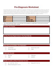
Preparation for TestingPRELIMINARY VEHICLE DIAGNOSIS WORKSHEETPRELIMINARY VEHICLE DIAGNOSIS WORKSHEETThe purpose of this form is to help you gather preliminary information onyour vehicle before you retrieve codes. By having a complete account ofyour vehicle's current problem(s), you will be able to systematically pinpointthe problem(s) by comparing your answers to the fault codes youretrieve. You can also provide this information to your mechanic to assistin diagnosis and help avoid costly and unnecessary repairs. It is importantfor you to complete this form to help you and/or your mechanic havea clear understanding of your vehicle's problems. An electronic versionof this Preliminary Vehicle Diagnosis Worksheet is available online atwww.canOBD2.com. You can complete the form online and print a copyto take to your mechanic.NAME:DATE:VIN*:YEAR:MAKE:MODEL:ENGINE SIZE:VEHICLE MILEAGE:*VIN: Vehicle Identification Number, found at the base of the windshieldon a metallic plate, or at the driver door latch area (consult your vehicleowner's manual for location).TRANSMISSION:❑ Automatic❑ ManualPlease check all applicable items in each category.DESCRIBE THE PROBLEM:14 OBD2
Preparation for TestingPRELIMINARY VEHICLE DIAGNOSIS WORKSHEETWHEN DID YOU FIRST NOTICE THE PROBLEM:❑ Just Started❑ Started Last Week❑ Started Last Month❑ Other:LIST ANY REPAIRS DONE IN THE PAST SIX MONTHS:PROBLEMS STARTING❑ No symptoms❑ Will not crankENGINE QUITS OR STALLS❑ No symptoms❑ Right after starting❑ When shifting into gear❑ During steady-speed driving❑ Cranks, but will not start❑ Starts, but takes a long time❑ Right after vehicle comes to a stop❑ While idling❑ During acceleration❑ When parkingIDLING CONDITIONS❑ No symptoms❑ Is too slow at all times❑ Is too fast❑ Is sometimes too fast or too slow❑ Is rough or uneven❑ Fluctuates up and downRUNNING CONDITIONS❑ No symptoms❑ Runs rough❑ Lacks power❑ Bucks and jerks❑ Poor fuel economy❑ Hesitates or stumbles onaccelerations❑ Backfires❑ Misfires or cuts out❑ Engine knocks, pings or rattles❑ Surges❑ Dieseling or run-onOBD2 15
Preparation for TestingPRELIMINARY VEHICLE DIAGNOSIS WORKSHEETAUTOMATIC TRANSMISSION PROBLEMS (if applicable)❑ No symptoms❑ Shifts too early or too late❑ Changes gear incorrectlyPROBLEM OCCURS❑ Vehicle does not move when ingear❑ Jerks or bucks❑ Morning ❑ Afternoon ❑ AnytimeENGINE TEMPERATURE WHEN PROBLEM OCCURS❑ Cold ❑ Warm ❑ HotDRIVING CONDITIONS WHEN PROBLEM OCCURS❑ Short - less than 2 miles ❑ With headlights on❑ 2 - 10 miles❑ During acceleration❑ Long - more than 10 miles ❑ Mostly driving downhill❑ Stop and go❑ Mostly driving uphill❑ While turning❑ Mostly driving level❑ While braking❑ Mostly driving curvy roads❑ At gear engagement❑ Mostly driving rough roads❑ With A/C operatingDRIVING HABITS❑ Mostly city driving❑ Highway❑ Park vehicle inside❑ Park vehicle outsideGASOLINE USED❑ 87 Octane❑ 89 Octane❑ Drive less than 10 miles per day❑ Drive 10 to 50 miles per day❑ Drive more than 50 miles per day❑ 91 Octane❑ More than 91 OctaneWEATHER CONDITIONS WHEN PROBLEM OCCURS❑ 32 - 55° F (0 - 13° C)❑ Above 55° F (13° C)❑ Below freezing (32° F / 0° C)CHECK ENGINE LIGHT / DASH WARNING LIGHT❑ Sometimes ON ❑ Always ON ❑ Never ONPECULIAR SMELLS❑ "Hot"❑ Sulfur ("rotten egg")❑ Burning rubber❑ Gasoline❑ Burning oil❑ ElectricalSTRANGE NOISES❑ Rattle❑ Knock❑ Squeak❑ Other16 OBD2
Preparation for TestingBEFORE YOU BEGINBEFORE YOU BEGINThe OBD2 <strong>Code</strong> <strong>Reader</strong> aidsin monitoring electronic- andemissions-related faults inyour vehicle and retrievingfault codes related to malfunctionsin these systems.Mechanical problems such aslow oil level or damagedhoses, wiring or electrical connectors can cause poor engine performanceand may also cause a fault code to set. Fix any known mechanicalproblems before performing any test. See your vehicle’s servicemanual or a mechanic for more information.Check the following areas before starting any test:■ Check the engine oil, power steering fluid, transmission fluid (ifapplicable), engine coolant and other fluids for proper levels. Top offlow fluid levels if needed.■ Make sure the air filter is clean and in good condition. Make sure allair filter ducts are properly connected. Check the air filter ducts forholes, rips or cracks.■ Make sure all engine belts are in good condition. Check for cracked,torn, brittle, loose or missing belts.■ Make sure mechanical linkages to engine sensors (throttle,gearshift position, transmission, etc.) are secure and properly connected.See your vehicle’s service manual for locations.■ Check all rubber hoses (radiator) and steel hoses (vacuum/fuel) forleaks, cracks, blockage or other damage. Make sure all hoses arerouted and connected properly.■ Make sure all spark plugs are clean and in good condition. Checkfor damaged, loose, disconnected or missing spark plug wires.■ Make sure the battery terminals are clean and tight. Check for corrosionor broken connections. Check for proper battery and chargingsystem voltages.■ Check all electrical wiring and harnesses for proper connection.Make sure wire insulation is in good condition, and there are nobare wires.■ Make sure the engine is mechanically sound. If needed, perform acompression check, engine vacuum check, timing check (if applicable),etc.OBD2 17
Preparation for TestingVEHICLE SERVICE MANUALSVEHICLE SERVICE MANUALSAlways refer to the manufacturer’s service manual for your vehiclebefore performing any test or repair procedures. Contact your local cardealership, auto parts store or bookstore for availability of these manuals.The following companies publish valuable repair manuals:■ Haynes Publications861 Lawrence DriveNewbury Park, California 91320Phone: 800-442-9637■ Mitchell International14145 Danielson StreetPoway, California 92064Phone: 888-724-6742■ Motor Publications5600 Crooks Road, Suite 200Troy, Michigan 48098Phone: 800-426-6867FACTORY SOURCESFord, GM, Chrysler, Honda, Isuzu, Hyundai and Subaru ServiceManuals■ Helm Inc.14310 Hamilton AvenueHighland Park, Michigan 48203Phone: 800-782-435618 OBD2
Using the <strong>Code</strong> <strong>Reader</strong>CODE RETRIEVAL PROCEDURECODE RETRIEVAL PROCEDURERetrieving and using Diagnostic Trouble <strong>Code</strong>s (DTCs) fortroubleshooting vehicle operation is only one part of anoverall diagnostic strategy.Never replace a part based only on the DTC definition.Each DTC has a set of testing procedures, instructionsand flow charts that must be followed to confirm the locationof the problem. This information is found in the vehicle'sservice manual. Always refer to the vehicle's service manualfor detailed testing instructions.Check your vehicle thoroughly before performingany test. See Before You Begin on page 17 fordetails.ALWAYS observe safety precautions whenever working on avehicle. See Safety Precautions on page 3 for more information.1. Turn the ignition off.2. Locate the vehicle's 16-pin Data LinkConnector (DLC). See page 5 for connectorlocation.Some DLCs have a plastic coverthat must be removed before connectingthe <strong>Code</strong> <strong>Reader</strong> cableconnector.If the <strong>Code</strong> <strong>Reader</strong> is ON, turn itOFF by pressing the POWER/LINKbutton BEFORE connectingthe <strong>Code</strong> <strong>Reader</strong> to the DLC.3. Connect the <strong>Code</strong> <strong>Reader</strong> cable connector to the vehicle’s DLC.The cable connector is keyed and will only fit one way.■ If you have problems connecting the cable connector to the DLC,rotate the connector 180° and try again.■ If you still have problems, check the DLC on the vehicle and onthe <strong>Code</strong> <strong>Reader</strong>. Refer to your vehicle’s service manual to properlycheck the vehicle’s DLC.4. When the <strong>Code</strong> <strong>Reader</strong>’s cable connector is properly connected tothe vehicle’s DLC, the unit automatically turns ON, and LINKS tothe vehicle’s on-board computer.OBD2 19
Using the <strong>Code</strong> <strong>Reader</strong>CODE RETRIEVAL PROCEDURE■ If the unit does not power on automatically when connected tothe vehicle’s DLC connector, it usually indicates there is nopower present at the vehicle’s DLC connector. Check your fusepanel and replace any burned-out fuses.■ If replacing the fuse(s) does not correct the problem, consult yourvehicle’s repair manual to identify the proper computer (PCM) fuse/circuit, and perform any necessary repairs before proceeding.5. Turn the ignition on. DO NOT start the engine.■ The <strong>Code</strong> <strong>Reader</strong> will automaticallystart a check of the vehicle’s computerto determine which type of communicationprotocol it is using. Whenthe <strong>Code</strong> <strong>Reader</strong> identifies the computer’scommunication protocol, acommunication link is established.The protocol type used by the vehicle’scomputer is shown on the LCD display.A PROTOCOL is a set of rules and procedures for regulatingdata transmission between computers, and betweentesting equipment and computers. As of this writing, fivedifferent types of protocols (ISO 9141, Keyword 2000,J1850 PWM, J1850 VPW and CAN) are in use by vehiclemanufacturers. The <strong>Code</strong> <strong>Reader</strong> automatically identifiesthe protocol type and establishes a communication linkwith the vehicle’s computer.6. After approximately 10~60 seconds, the <strong>Code</strong> <strong>Reader</strong> will retrieveand display any Diagnostic Trouble <strong>Code</strong> and Monitor Statusretrieved from the vehicle’s computer memory.■ If the <strong>Code</strong> <strong>Reader</strong> fails to link to the vehicle’s computer a “LinkingFailed” message shows on the <strong>Code</strong><strong>Reader</strong>’s LCD display.- Verify the connection at the DLCand verify the ignition is ON.- Turn the ignition OFF, wait 5 seconds,then turn back ON to resetthe computer.- Ensure your vehicle is OBD2 compliant. See VehiclesCovered on page 5 for vehicle compliance verification information.20 OBD2
Using the <strong>Code</strong> <strong>Reader</strong>CODE RETRIEVAL PROCEDURE■ The <strong>Code</strong> <strong>Reader</strong> will automaticallyre-link to the vehicle’s computer every30 seconds to refresh the data beingretrieved. When data is being refreshed,the message “One momentAuto – link in progress” is shown on theLCD display. This action repeats aslong as the <strong>Code</strong> <strong>Reader</strong> is communicatingwith the vehicle’s computer.■ The <strong>Code</strong> <strong>Reader</strong> will display a codeonly if codes are present in the vehicle’scomputer memory. If no codesare present, a “No DTC’s are presentlystored in the vehicle’s computer” isdisplayed.■ The <strong>Code</strong> <strong>Reader</strong> is capable of retrieving and storing up to 32codes in memory, for immediate or later viewing.7. To read the display:Refer to Display Functions on page 12 for a descriptionof LCD display elements.■ A visible icon indicates that the <strong>Code</strong> <strong>Reader</strong> is being poweredthrough the vehicle’s DLC connector.■ A visible icon indicates that the <strong>Code</strong> <strong>Reader</strong> is linked to(communicating with) the vehicle’s computer.■ The I/M Monitor Status icons indicate the type and number ofMonitors the vehicle supports, and provides indications of thecurrent status of the vehicle’s Monitors. A solid Monitor icon indicatesthe associated Monitor has run and completed its testing.A blinking Monitor icon indicates the associated Monitor hasnot run and completed its testing.■ The upper right hand corner of thedisplay shows the number of the codecurrently being displayed, the totalnumber of codes retrieved, the typeof code (G = Generic; M =Manufacturer Specific), and whetheror not the displayed code commandedthe MIL on. If the code being displayedis a PENDING code, the PENDING icon is shown.OBD2 21
Using the <strong>Code</strong> <strong>Reader</strong>CODE RETRIEVAL PROCEDUREFreeze Frame data is always associated with the“Priority <strong>Code</strong>” (identified as <strong>Code</strong> #1 in the <strong>Code</strong><strong>Reader</strong>’s display). If the FREEZE FRAME icon is litwhen the “Priority <strong>Code</strong>” (<strong>Code</strong> #1) is displayed on the<strong>Code</strong> <strong>Reader</strong>’s screen, it indicates that there is FreezeFrame data associated with this code, and the vehicle’scomputer has saved it in its memory.■ The Diagnostic Trouble <strong>Code</strong> (DTC) and related code definitionare shown in the lower section of the LCD display.In the case of long code definitions, a small arrow isshown in the upper/lower right-hand corner of the codedisplay area to indicate the presence of additional information.Use the SCROLL button, as necessary, toview the additional information. When the end of thescreen is reached, pressing the button again returns tothe top of the screen.8. Read and interpret Diagnostic Trouble <strong>Code</strong>s/system conditionusing the LCD display and the green, yellow and red LEDs.The green, yellow and red LEDs are used (with the LCDdisplay) as visual aids to make it easier to determineengine system conditions.■ Green LED – Indicates that allengine systems are “OK” and operatingnormally. All monitors supportedby the vehicle have run and performedtheir diagnostic testing, andno trouble codes are present. A zerowill show on the <strong>Code</strong> <strong>Reader</strong>’s LCDdisplay, and all Monitor icons will besolid.■ Yellow LED – Indicates one of the following conditions:A. A PENDING CODE IS PRESENT – Ifthe yellow LED is illuminated, it mayindicate a Pending code is present.Check the <strong>Code</strong> <strong>Reader</strong>’s LCD displayfor confirmation. A Pending codeis confirmed by the presence of anumeric code and the word PEND-ING on the <strong>Code</strong> <strong>Reader</strong>’s LCD display.22 OBD2
Using the <strong>Code</strong> <strong>Reader</strong>CODE RETRIEVAL PROCEDUREB. MONITOR NOT RUN STATUS – If the<strong>Code</strong> <strong>Reader</strong>’s LCD display shows azero (indicating there are no DTC’spresent in the vehicle’s computermemory), but the yellow LED is illuminated,it may be an indication thatsome of the Monitors supported bythe vehicle have not yet run and completedtheir diagnostic testing. Checkthe <strong>Code</strong> <strong>Reader</strong>’s LCD display for confirmation. All Monitoricons that are blinking have not yet run and completed theirdiagnostic testing; all Monitor icons that are solid have run andcompleted their diagnostic testing.■ Red LED – Indicates there is a problemwith one or more of the vehicle’ssystems. The red LED is also used toindicate that DTC(s) are present (displayedon the <strong>Code</strong> <strong>Reader</strong>’s screen).In this case, the Multifunction Indicator(Check Engine) lamp on the vehicle’sinstrument panel will be illuminated.■ DTC’s that start with “P0”, “P2” and some “P3” are consideredGeneric (Universal). All Generic DTC definitions are the same onall OBD2 equipped vehicles. The <strong>Code</strong> <strong>Reader</strong> automatically displaysthe code definitions for Generic DTC’s.■ DTC’s that start with “P1” and some“P3” are Manufacturer Specific codesand their code definitions vary witheach vehicle manufacturer. When aManufacturer Specific DTC is retrieved,the LCD display shows a list ofvehicle manufacturers. Use theSCROLL button, as necessary, to highlight the appropriatemanufacturer, then press the ENTER/FF button to displaythe correct code definition for your vehicle.When the last manufacturer in the list is reached, pressingthe SCROLL button again will return to the first manufacturerin the list.OBD2 23
Using the <strong>Code</strong> <strong>Reader</strong>CODE RETRIEVAL PROCEDUREIf the manufacturer for your vehicle is not listed, use theSCROLL button, as necessary, to select Other manufacturerand press the ENTER/FF button for additionalDTC information.If the Manufacturer Specificdefinition for the currently displayedcode is not available, anadvisory message shows onthe <strong>Code</strong> <strong>Reader</strong>’s LCD display.9. If more than one code was retrieved press the DTC SCROLLbutton, as necessary, to display additional codes one at a time.■ Whenever the Scroll function is used to view additional codes,the <strong>Code</strong> <strong>Reader</strong>’s communication link with the vehicle’s computerdisconnects. To re-establish communication, press theLINK button again.10. Freeze Frame Data (if available) can be viewed at any time (exceptMENU mode) by pressing the ENTER/FF button.■ In OBD2 systems, when an emissions-related engine malfunctionoccurs that causes a DTC to set, a record or snapshot ofengine conditions at the time that the malfunction occurred isalso saved in the vehicle’s computermemory. The record saved is calledFreeze Frame data. Saved engineconditions include, but are not limitedto: engine speed, open or closedloop operation, fuel system commands,coolant temperature, calculatedload value, fuel pressure, vehicle speed, air flow rate, andintake manifold pressure.If more than one malfunction is present that causes morethan one DTC to be set, only the code with the highest prioritywill contain Freeze Frame data. The code designated“01” on the <strong>Code</strong> <strong>Reader</strong> display is referred to as thePRIORITY code, and Freeze Frame data always refers tothis code. The priority code is also the one that has commandedthe MIL on.24 OBD2
Using the <strong>Code</strong> <strong>Reader</strong>ERASING DIAGNOSTIC TROUBLE CODES (DTCs)If Freeze Frame data is notavailable for the code shownon the LCD display when theENTER/FF button ispressed, an advisory messageshows on the LCD display.Press the DTC SCROLLbutton to return to the previouscode display.11. Determine engine system(s) condition by viewing the <strong>Code</strong><strong>Reader</strong>’s LCD display for any retrieved Diagnostic Trouble <strong>Code</strong>sand code definitions, and interpreting the green, yellow and redLEDs.■ If DTC’s were retrieved and you are going to perform the repairsyourself, proceed by consulting the Vehicle’s Service RepairManual for testing instructions, testing procedures, and flowcharts related to retrieved code(s).■ If you plan to take the vehicle to a professional to have it serviced,complete the Preliminary Vehicle Diagnosis Worksheeton page 14 and take it together with the retrieved codes, freezeframe data and LED information to aid in the troubleshootingprocedure.■ To prolong battery life, the <strong>Code</strong> <strong>Reader</strong> automatically shuts“Off” approximately three minutes after it is disconnected fromthe vehicle. The DTCs retrieved and Monitor Status will remain inthe <strong>Code</strong> <strong>Reader</strong>’s memory, and may be viewed at any time byturning the unit “On”. If the <strong>Code</strong> <strong>Reader</strong> is re-linked to a vehicleto retrieve codes/data, any prior codes/data in its memory areautomatically cleared.The Diagnostic information retrieved can be transferred toa personal computer (PC) with the use of an optional Tek-Link program. See documentation that comes with programfor instructions.ERASING DIAGNOSTIC TROUBLE CODES (DTCs)When the <strong>Code</strong> <strong>Reader</strong>’s ERASE function is used to eraseDTCs from the vehicle's on-board computer, "FreezeFrame" data and manufacturer-specific enhanced dataare also erased.If you plan to take the vehicle to a Service Center for repair, DO NOTerase the codes from the vehicle's computer. If the codes are erased,valuable information that might help the technician troubleshoot theproblem will also be erased.Erase DTCs from the computer's memory as follows:OBD2 25
Using the <strong>Code</strong> <strong>Reader</strong>ERASING DIAGNOSTIC TROUBLE CODES (DTCs)When DTCs are erased from the vehicle's computer memory,the I/M Readiness Monitor Status program resets the statusof all Monitors to a not run "flashing" condition. To set allof the Monitors to a DONE status, an OBD 2 Drive Cyclemust be performed. Refer to your vehicle's service manual forinformation on how to perform an OBD 2 Drive Cycle for thevehicle under test.The <strong>Code</strong> <strong>Reader</strong> must be connectedto the vehicle’s DLC toerase the codes from the computer’smemory. If you press theERASE button when the<strong>Code</strong> <strong>Reader</strong> is not connected tothe vehicle’s DLC, the eraseinstruction screen displays.1. If not connected already, connect the<strong>Code</strong> <strong>Reader</strong> to the vehicle's DLC, andturn the ignition "On.” (If the <strong>Code</strong> <strong>Reader</strong>is already connected and linked to thevehicle's computer, proceed directly tostep 3. If not, continue to step 2.)2. Perform the <strong>Code</strong> Retrieval procedureas described on page 19. Wait until thecodes are displayed on the <strong>Code</strong><strong>Reader</strong>s LCD and then proceed to step3.3. Press and release the ERASE button.A confirmation message shows onthe LCD display.- If you are sure you want to proceed press the ERASE buttonagain to erase DTCs from the vehicle’s computer.- If you do not want to continue with the erase process, press thePOWER/LINK button to exit the erase mode.4. If you chose to erase DTCs, a progress screen displays while theerase function is in progress.■ When the erase process has completed, the <strong>Code</strong> <strong>Reader</strong> automaticallyre-links to the vehicle, and displays any new informationretrieved. Some of the Monitor icons will be flashing to indicatethat the Monitors have been re-set.26 OBD2
Using the <strong>Code</strong> <strong>Reader</strong>I/M READINESS TESTINGErasing DTCs does not fix the problem(s) that caused thecode(s) to be set. If proper repairs to correct the problem thatcaused the code(s) to be set are not made, the code(s) willappear again (and the check engine light will illuminate) assoon as the vehicle is driven long enough for its Monitors tocomplete their testing.I/M READINESS TESTINGI/M is an Inspection and Maintenance program legislated by theGovernment to meet federal clean-air standards.The program requires that a vehicle be taken periodically to anEmissions Station for an "Emissions Test" or "Smog Check,” where theemissions-related components and systems are inspected and testedfor proper operation. Emissions Tests are generally performed once ayear, or once every two years.On OBD 2 systems, the I/M program is enhanced by requiring vehicles tomeet stricter test standards. One of the tests instituted by the FederalGovernment is called I/M 240. On I/M 240, the vehicle under test is drivenunder different speeds and load conditions on a dynamometer for 240seconds, while the vehicle's emissions are measured.Emissions tests vary depending on the geographic or regionalarea in which the vehicle is registered. If the vehicle is registeredin a highly urbanized area, the I/M 240 is probably thetype of test required. If the vehicle is registered in a rural area,the stricter “dynamometer type” test may not be required.I/M Readiness MonitorsI/M Readiness shows whether the various emissions-related systemson the vehicle are operating properly and are ready for Inspection andMaintenance testing.State and Federal Governments enacted Regulations, Procedures andEmission Standards to ensure that all emissions-related componentsand systems are continuously or periodically monitored, tested anddiagnosed whenever the vehicle is in operation. It also requires vehiclemanufacturers to automatically detect and report any problems orfaults that may increase the vehicle's emissions to an unacceptable level.The vehicle's emissions control system consists of several componentsor sub-systems (Oxygen Sensor, Catalytic Converter, EGR, FuelSystem, etc.) that aid in reducing vehicle emissions.To have an efficient Vehicle Emission Control System, all the emissions-relatedcomponents and systems must work correctly wheneverthe vehicle is in operation.OBD2 27
Using the <strong>Code</strong> <strong>Reader</strong>I/M READINESS TESTINGTo comply with State and Federal Government regulations, vehiclemanufacturers designed a series of special computer programs called"Monitors" that are programmed into the vehicle's computer. Each ofthese Monitors is specifically designed to run tests and diagnostics ona specific emissions-related component or system (Oxygen Sensor,Catalytic Converter, EGR Valve, Fuel System, etc.) to ensure theirproper operation. Currently, there are a maximum of eleven Monitorsavailable for use.To learn more about Emissions Inspection and Maintenance(I/M) Readiness Monitors, see OBD 2 MONITORS on page 42.Each Monitor has a specific function to testand diagnose only its designated emissionsrelatedcomponent or system. The names of theMonitors (Oxygen Sensor Monitor, CatalystMonitor, EGR Monitor, Misfire Monitor, etc.)describe which component or system each Monitoris designed to test and diagnose.Emissions Inspection and Maintenance (I/M) ReadinessMonitor Status InformationI/M Readiness Monitor Status shows which of the vehicle's Monitorshave run and completed their diagnosis and testing, and which oneshave not yet run and completed testing and diagnosis of their designatedsections of the vehicle's emissions system.■ If a Monitor was able to meet all the conditions required to enable itto perform the self-diagnosis and testing of its assigned engine system,it means the monitor "HAS RUN.”■ If a Monitor has not yet met all the conditions required for it to performthe self-diagnosis and testing of its assigned engine system; itmeans the Monitor "HAS NOT RUN.”The Monitor Run/Not Run status does not show whetheror not a problem exists in a system. Monitor status onlyindicates whether a particular Monitor has or has not runand performed the self-diagnosis and testing of its associatedsystem.28 OBD2
Using the <strong>Code</strong> <strong>Reader</strong>I/M READINESS TESTINGPerforming I/M Readiness Quick CheckWhen a vehicle first comes from the factory, all Monitors indicatea “HAVE RUN” status. This indicates that all Monitorshave run and completed their diagnostic testing. The “HAVERUN” status remains in the computer's memory, unless theDiagnostic Trouble <strong>Code</strong>s are erased or the vehicle's computermemory is cleared.The <strong>Code</strong> <strong>Reader</strong> allows you to retrieve Monitor/System Status Informationto help you determine if the vehicle is ready for an EmissionsTest (Smog Check). In addition to retrieving Diagnostic Trouble <strong>Code</strong>s,the <strong>Code</strong> <strong>Reader</strong> also retrieves Monitor Run/Not Run status. This informationis very important since different areas of the state/country havedifferent emissions laws and regulations concerning Monitor Run/NotRun status.Before an Emissions Test (Smog Check) can be performed, your vehiclemust meet certain rules, requirements and procedures legislatedby the Federal and state (country) governments where you live.1. In most areas, one of the requirements that must be met before avehicle is allowed to be Emissions Tested (Smog Checked) is thatthe vehicle does not have any Diagnostic Trouble <strong>Code</strong>s present(with the exception of PENDING Diagnostic Trouble <strong>Code</strong>s).2. In addition to the requirement that no Diagnostic Trouble <strong>Code</strong>s bepresent, some areas also require that all the Monitors that a particularvehicle supports indicate a "Has Run" status condition beforean Emissions Check may be performed.3. Other areas may only require that some (but not all) Monitors indicatea "Has Run" status before an Emissions Test (Smog Check)may be performed.Monitors with a "Has Run" status indicate that all therequired conditions they needed to perform diagnosisand testing of their assigned engine area (system) havebeen met, and all diagnostic testing has completed successfully.Monitors with a "Has Not Run" status have not yet metthe conditions they need to perform diagnosis and testingof their assigned engine area (system), and have notbeen able to perform diagnostic testing on that system.The green, yellow and red LEDs provide a quick way to help you determineif a vehicle is ready for an Emissions Test (Smog Check). Followthe instructions below to perform the Quick Check.Perform the <strong>Code</strong> Retrieval Procedure as described on page 19,then interpret the LED indications as follows:OBD2 29
Using the <strong>Code</strong> <strong>Reader</strong>I/M READINESS TESTINGInterpreting I/M Readiness Test Results1. GREEN LED - Indicates that all enginesystems are "OK" and operating normally(all Monitors supported by thevehicle have run and performed theirself-diagnostic testing). The vehicle isready for an Emissions Test (SmogCheck), and there is a good possibilitythat it can be certified.2. YELLOW LED - Determine from the <strong>Code</strong> Retrieval Procedure(page 19) which of the two possible conditions is causing the yellowLED to light.■ If a "PENDING" Diagnostic Trouble<strong>Code</strong> is causing the yellow LED tolight, it is possible that the vehicle willbe allowed to be tested for emissionsand certified. Currently, most areas(states / countries) will allow anEmissions Test (Smog Check) to beperformed if the only code in the vehicle'scomputer is a "PENDING"Diagnostic Trouble <strong>Code</strong>.■ If the illumination of the Yellow LED isbeing caused by monitors that “havenot run” their diagnostic testing, thenthe issue of the vehicle being readyfor an Emissions Test (Smog Check)depends on the emissions regulationsand laws of your local area.- Some areas require that all Monitors indicate a "Has Run" statusbefore they allow an Emissions Test (Smog Check) to beperformed. Other areas only require that some, but not all,Monitors have run their self-diagnostic testing before anEmissions Test (Smog Check) may be performed.From the code retrieval procedure, determine the status ofeach Monitor (a solid Monitor icon shows Monitor "Has Run"status, a flashing Monitor icon indicates "Has Not Run" status).Take this information to an emissions professional todetermine (based on your test results) if your vehicle is readyfor an Emissions Test (Smog Check).30 OBD2
Using the <strong>Code</strong> <strong>Reader</strong>I/M READINESS TESTING3. RED LED - Indicates there is a problemwith one or more of the vehicle's systems.A vehicle displaying a red LED isdefinitely not ready for an EmissionsTest (Smog Check). The red LED is alsoan indication that there are DiagnosticTrouble <strong>Code</strong>(s) present (displayed onthe <strong>Code</strong> <strong>Reader</strong>'s screen). TheMultifunction Indicator (Check Engine)Lamp on the vehicle's instrument panel will light steady. The problemthat is causing the red LED to light must be repaired before anEmissions Test (Smog Check) can be performed. It is also suggestedthat the vehicle be inspected/repaired before driving the vehiclefurther.If the Red LED was obtained, there is a definite problem present inthe system(s). In these cases, you have the following options.■ Repair the vehicle yourself. If you are going to perform therepairs yourself, proceed by reading the vehicle service manualand following all its procedures and recommendations.■ Take the vehicle to a professional to have it serviced. The problem(s)causing the red LED to light must be repaired before thevehicle is ready for an Emissions Test (Smog Check).Using the I/M Readiness Monitor Status to Confirm a RepairThe I/M Readiness Monitor Status function can be used (after repair ofa fault has been performed) to confirm that the repair has been performedcorrectly, and/or to check for Monitor Run Status. Use the followingprocedure to determine I/M Readiness Monitor Status:1. Using retrieved Diagnostic Trouble <strong>Code</strong>s (DTCs) and code definitionsas a guide, and following manufacturer's repair procedures,repair the fault or faults as instructed.2. After the fault or faults have been repaired, connect the <strong>Code</strong><strong>Reader</strong> to the vehicle's DLC and erase the code or codes from thevehicle's computer memory.■ See page 25 for procedures to erase DTCs from the vehicle's onboardcomputer.■ Write the codes down on a piece of paper for reference beforeerasing.3. After the erase procedure is performed, most of the Monitor iconson the <strong>Code</strong> <strong>Reader</strong>’s LCD display will be flashing. Leave the <strong>Code</strong><strong>Reader</strong> connected to the vehicle, and perform a Trip Drive Cycle foreach "flashing" Monitor:Misfire, Fuel and Comprehensive Component Monitors runcontinuously and their icons will always be on solid, evenafter the erase function is performed.OBD2 31
Using the <strong>Code</strong> <strong>Reader</strong>I/M READINESS TESTING■ Each DTC is associated with a specific Monitor. Consult the vehicle'sservice manual to identify the Monitor (or Monitors) associatedwith the faults that were repaired. Follow the manufacturer'sprocedures to perform a Trip Drive Cycle for the appropriateMonitors.■ While observing the Monitor icons on the <strong>Code</strong> <strong>Reader</strong>’s LCDdisplay, perform a Trip Drive Cycle for the appropriate Monitor orMonitors.If the vehicle needs to be driven in order to perform a TripDrive Cycle, ALWAYS have a second person help you.One person should drive the vehicle while the other personobserves the Monitor icons on the <strong>Code</strong> <strong>Reader</strong> forMonitor RUN status. Trying to drive and observe the<strong>Code</strong> <strong>Reader</strong> at the same time is dangerous, and couldcause a serious traffic accident.4. When a Monitor's Trip Drive Cycle is performed properly, theMonitor icon on the <strong>Code</strong> <strong>Reader</strong>’s LCD display changes from"flashing" to "solid,” indicating that the Monitor has run and finishedits diagnostic testing.■ If, after the Monitor has run, the MIL on the vehicle's dash is notlit, and no stored or pending codes associated with that particularMonitor are present in the vehicle's computer, the repair wassuccessful.■ If, after the Monitor has run, the MIL on the vehicle's dash lightsand/or a DTC associated with that Monitor is present in the vehicle'scomputer, the repair was unsuccessful. Refer to the vehicle'sservice manual and recheck repair procedures.32 OBD2
Onboard DiagnosticsCOMPUTER ENGINE CONTROLSCOMPUTER ENGINE CONTROLSThe Introduction of Electronic Engine ControlsElectronic Computer Control Systems make it possiblefor vehicle manufacturers to comply with the tougher emissionsand fuel efficiency standards mandated byState and Federal Governments.As a result of increased air pollution (smog) in largecities, such as Los Angeles, the California Air ResourcesBoard (CARB) and the Environmental Protection Agency(EPA) set new regulations and air pollution standards todeal with the problem. To further complicate matters, theenergy crisis of the early 1970s caused a sharp increase infuel prices over a short period. As a result, vehicle manufacturerswere not only required to comply with the new emissionsstandards, they also had to make their vehicles more fuelefficient.Most vehicles were required to meet a miles-per-gallon(MPG) standard set by the U.S. Federal Government.Precise fuel delivery and spark timing are needed to reduce vehicleemissions. Mechanical engine controls in use at the time (such as ignitionpoints, mechanical spark advance and the carburetor) respondedtoo slowly to driving conditions to properly control fuel delivery andspark timing. This made it difficult for vehicle manufacturers to meetthe new standards.A new Engine Control System had to be designed and integrated withthe engine controls to meet the stricter standards. The new system hadto:■ Respond instantly to supply the proper mixture of air and fuel forany driving condition (idle, cruising, low-speed driving, high-speeddriving, etc.).■ Calculate instantly the best time to “ignite” the air/fuel mixture formaximum engine efficiency.■ Perform both these tasks without affecting vehicle performance orfuel economy.Vehicle Computer Control Systems can perform millions of calculationseach second. This makes them an ideal substitute for the slowermechanical engine controls. By switching from mechanical to electronicengine controls, vehicle manufacturers are able to control fueldelivery and spark timing more precisely. Some newer ComputerControl Systems also provide control over other vehicle functions,such as transmission, brakes, charging, body, and suspension systems.OBD2 33
Onboard DiagnosticsCOMPUTER ENGINE CONTROLSThe Basic Engine Computer Control SystemThe Computer Control System consists of an on-boardcomputer and several related control devices (sensors,switches, and actuators).The on-board computer is the heart of the ComputerControl System. The computer contains several programswith preset reference values for air/fuel ratio, spark or ignitiontiming, injector pulse width, engine speed, etc.Separate values are provided for various driving conditions,such as idle, low speed driving, high-speed driving, low load,or high load. The preset reference values represent the idealair/fuel mixture, spark timing, transmission gear selection,etc., for any driving condition. These values are programmed by thevehicle manufacturer, and are specific to each vehicle model.Most on-board computers are located inside the vehicle behind thedashboard, under the passenger’s or driver’s seat, or behind the rightkick panel. However, some manufacturers may still position it in theengine compartment.Vehicle sensors, switches, and actuators are located throughout theengine, and are connected by electrical wiring to the on-boardcomputer. These devices include oxygen sensors, coolant temperaturesensors, throttle position sensors, fuel injectors, etc. Sensors andswitches are input devices. They provide signals representing currentengine operating conditions to the computer. Actuators are outputdevices. They perform actions in response to commands receivedfrom the computer.The on-board computer receives information inputs from sensors andswitches located throughout the engine. These devices monitor criticalengine conditions such as coolant temperature, engine speed, engineload, throttle position, air/fuel ratio etc.OUTPUT DEVICESFuel InjectorsIdle Air ControlEGR ValveIgnition ModuleTYPICAL COMPUTERCONTROL SYSTEMOn-BoardComputerINPUT DEVICESCoolant Temperature SensorThrottle Position SensorFuel InjectorsINPUT DEVICESOxygen Sensors34 OBD2
Onboard DiagnosticsCOMPUTER ENGINE CONTROLSThe computer compares the values received from these sensors withits preset reference values, and makes corrective actions as neededso that the sensor values always match the preset reference values forthe current driving condition. The computer makes adjustments bycommanding other devices such as the fuel injectors, idle air control,EGR valve or Ignition Module to perform these actions.Vehicle operating conditions are constantly changing. The computercontinuously makes adjustments or corrections (especially to theair/fuel mixture and spark timing) to keep all the engine systems operatingwithin the preset reference values.On-Board Diagnostics - First Generation (OBD 1)With the exception of some 1994 and 1995 vehicles,most vehicles from 1982 to 1995 are equipped withsome type of first generation On-Board Diagnostics.Beginning in 1988, California’s Air Resources Board(CARB), and later the Environmental Protection Agency(EPA) required vehicle manufacturers to include a selfdiagnosticprogram in their on-board computers. The programwould be capable of identifying emissions-related faultsin a system. The first generation of Onboard Diagnosticscame to be known as OBD 1.OBD 1 is a set of self-testing and diagnostic instructions programmedinto the vehicle’s on-board computer. The programs arespecifically designed to detect failures in the sensors, actuators,switches and wiring of the various vehicle emissions-related systems.If the computer detects a failure in any of these components or systems,it lights an indicator on the dashboard to alert the driver. The indicatorlights only when an emissions-related problem is detected.The computer also assigns a numeric code for each specific problemthat it detects, and stores these codes in its memory for later retrieval.These codes can be retrieved from the computer’s memory with theuse of a “<strong>Code</strong> <strong>Reader</strong>” or a “Scan Tool.”OBD2 35
Onboard DiagnosticsCOMPUTER ENGINE CONTROLSOn-Board Diagnostics - Second Generation (OBD 2)In addition to performing all the functionsof the OBD 1 System, the OBD 2System has been enhanced with new The OBD 2 System isDiagnostic Programs. These programs an enhancement of theclosely monitor the functions of variousemissions-related componentsOBD 1 System.and systems (as well as other systems)and make this information readily available (withthe proper equipment) to the technician for evaluation.The California Air Resources Board (CARB) conductedstudies on OBD 1 equipped vehicles. The information thatwas gathered from these studies showed the following:■ A large number of vehicles had deteriorating or degradedemissions-related components. These components werecausing an increase in emissions.■ Because OBD 1 systems only detect failed components, thedegraded components were not setting codes.■ Some emissions problems related to degraded components onlyoccur when the vehicle is being driven under a load. The emissionchecks being conducted at the time were not performed under simulateddriving conditions. As a result, a significant number of vehicleswith degraded components were passing Emissions Tests.■ <strong>Code</strong>s, code definitions, diagnostic connectors, communicationprotocols and emissions terminology were different for each manufacturer.This caused confusion for the technicians working on differentmake and model vehicles.To address the problems made evident by this study, CARB and the EPApassed new laws and standardization requirements. These laws requiredthat vehicle manufacturers to equip their new vehicles with devices capableof meeting all of the new emissions standards and regulations. It wasalso decided that an enhanced on-board diagnostic system, capable ofaddressing all of these problems, was needed.This new system is knownas “On-Board Diagnostics Generation Two (OBD 2).” The primaryobjective of the OBD 2 system is to comply with the latest regulations andemissions standards established by CARB and the EPA.The Main Objectives of the OBD 2 System are:■ To detect degraded and/or failed emissions-related components orsystems that could cause tailpipe emissions to exceed by 1.5 timesthe Federal Test Procedure (FTP) standard.■ To expand emissions-related system monitoring. This includes a setof computer run diagnostics called Monitors. Monitors perform diagnosticsand testing to verify that all emissions-related componentsand/or systems are operating correctly and within the manufacturer’sspecifications.36 OBD2
Onboard DiagnosticsCOMPUTER ENGINE CONTROLS■ To use a standardized Diagnostic Link Connector (DLC) in all vehicles.(Before OBD 2, DLCs were of different shapes and sizes.)■ To standardize the code numbers, code definitions and languageused to describe faults. (Before OBD 2, each vehicle manufacturerused their own code numbers, code definitions and language todescribe the same faults.)■ To expand the operation of the Malfunction Indicator Lamp (MIL).■ To standardize communication procedures and protocols betweenthe diagnostic equipment (Scan Tools, <strong>Code</strong> <strong>Reader</strong>s, etc.) and thevehicle’s on-board computer.OBD 2 TerminologyThe following terms and their definitions are related to OBD 2 systems.Read and reference this list as needed to aid in the understanding ofOBD 2 systems.■ Powertrain Control Module (PCM) - The PCM is the OBD 2accepted term for the vehicle’s “on-board computer.” In addition tocontrolling the engine management and emissions systems, thePCM also participates in controlling the powertrain (transmission)operation. Most PCMs also have the ability to communicate withother computers on the vehicle (ABS, ride control, body, etc.).■ Monitor - Monitors are “diagnostic routines” programmed into thePCM. The PCM utilizes these programs to run diagnostic tests, andto monitor operation of the vehicle’s emissions-related componentsor systems to ensure they are operating correctly and within thevehicle’s manufacturer specifications. Currently, up to elevenMonitors are used in OBD 2 systems. Additional Monitors will beadded as the OBD 2 system is further developed.Not all vehicles support all eleven Monitors.■ Enabling Criteria - Each Monitor is designed to test and monitorthe operation of a specific part of the vehicle’s emissions system(EGR system, oxygen sensor, catalytic converter, etc.). A specificset of “conditions” or “driving procedures” must be met before thecomputer can command a Monitor to run tests on its related system.These “conditions” are known as “Enabling Criteria.” Therequirements and procedures vary for each Monitor. Some Monitorsonly require the ignition key to be turned “On” for them to run andcomplete their diagnostic testing. Others may require a set of complexprocedures, such as, starting the vehicle when cold, bringing itto operating temperature, and driving the vehicle under specificconditions before the Monitor can run and complete its diagnostictesting.OBD2 37
Onboard DiagnosticsCOMPUTER ENGINE CONTROLS■ Monitor Has/Has Not Run - The terms “Monitor has run” or“Monitor has not run” are used throughout this manual. “Monitorhas run,” means the PCM has commanded a particular Monitor toperform the required diagnostic testing on a system to ensure thesystem is operating correctly (within factory specifications). Theterm “Monitor has not run” means the PCM has not yet commandeda particular Monitor to perform diagnostic testing on itsassociated part of the emissions system.■ Trip - A Trip for a particular Monitor requires that the vehicle is beingdriven in such a way that all the required “Enabling Criteria” for theMonitor to run and complete its diagnostic testing are met. The “TripDrive Cycle” for a particular Monitor begins when the ignition key isturned “On.” It is successfully completed when all the “EnablingCriteria” for the Monitor to run and complete its diagnostic testingare met by the time the ignition key is turned “Off.” Since each ofthe eleven monitors is designed to run diagnostics and testing on adifferent part of the engine or emissions system, the “Trip DriveCycle” needed for each individual Monitor to run and completevaries.■ OBD 2 Drive Cycle - An OBD 2 Drive Cycle is an extended set ofdriving procedures that takes into consideration the various types ofdriving conditions encountered in real life. These conditions mayinclude starting the vehicle when it is cold, driving the vehicle at asteady speed (cruising), accelerating, etc. An OBD 2 Drive Cyclebegins when the ignition key is turned “On” (when cold) and endswhen the vehicle has been driven in such a way as to have all the“Enabling Criteria” met for all its applicable Monitors. Only thosetrips that provide the Enabling Criteria for all Monitors applicable tothe vehicle to run and complete their individual diagnostic testsqualify as an OBD 2 Drive Cycle. OBD 2 Drive Cycle requirementsvary from one model of vehicle to another. Vehicle manufacturersset these procedures. Consult your vehicle’s service manual forOBD 2 Drive Cycle procedures.Do not confuse a “Trip” Drive Cycle with an OBD 2 DriveCycle. A “Trip” Drive Cycle provides the “Enabling Criteria” forone specific Monitor to run and complete its diagnostic testing.An OBD 2 Drive Cycle must meet the “Enabling Criteria”for all Monitors on a particular vehicle to run and completetheir diagnostic testing.■ Warm-up Cycle - Vehicle operation after an engine off periodwhere engine temperature rises at least 40°F (22°C) from its temperaturebefore starting, and reaches at least 160°F (70°C). ThePCM uses warm-up cycles as a counter to automatically erase aspecific code and related data from its memory. When no faultsrelated to the original problem are detected within a specified numberof warm-up cycles, the code is erased automatically.38 OBD2
Onboard DiagnosticsDIAGNOSTIC TROUBLE CODES (DTCs)DIAGNOSTIC TROUBLE CODES (DTCs)Diagnostic Trouble <strong>Code</strong>s (DTCs) aremeant to guide you to the proper serviceprocedure in the vehicle’s servicemanual. DO NOT replace parts basedonly on DTCs without first consultingthe vehicle’s service manual for propertesting procedures for that particularsystem, circuit or component.Diagnostic Trouble<strong>Code</strong>s (DTCs) arecodes that identify aspecific problem area.DTCs are alphanumeric codes that are used to identify aproblem that is present in any of the systems that are monitoredby the on-board computer (PCM). Each trouble codehas an assigned message that identifies the circuit, componentor system area where the problem was found.OBD 2 diagnostic trouble codes are made up of five characters:■ The 1st character is a letter. It identifies the “main system” wherethe fault occurred (Body, Chassis, Powertrain, or Network).■ The 2nd character is a numeric digit. It identifies the “type” of code(Generic or Manufacturer-Specific).Generic DTCs are codes that are used by all vehicle manufacturers.The standards for generic DTCs, as well as theirdefinitions, are set by the Society of Automotive Engineers(SAE).Manufacturer-Specific DTCs are codes that are controlledby the vehicle manufacturers. The Federal Government doesnot require vehicle manufacturers to go beyond the standardizedgeneric DTCs in order to comply with the newOBD2 emissions standards. However, manufacturers are freeto expand beyond the standardized codes to make their systemseasier to diagnose.■ The 3rd character is a numeric digit. It identifies the specific systemor sub-system where the problem is located.■ The 4th and 5th characters are numeric digits. They identify thesection of the system that is malfunctioning.OBD2 39
Onboard DiagnosticsDIAGNOSTIC TROUBLE CODES (DTCs)OBD 2 DTC EXAMPLEP0201 - Injector Circuit Malfunction, Cylinder 1B - BodyC - ChassisP - PowertrainU - NetworkP 0 2 0 10123----GenericManufacturer SpecificGenericIncludes both Generic and ManufacturerSpecific <strong>Code</strong>sIdentifies the system where theproblem is located:12345678--------Fuel and Air MeteringFuel and Air Metering (injector circuitmalfunction only)Ignition System or MisfireAuxiliary Emission Control SystemVehicle Speed Control and Idle ControlSystemComputer Output CircuitsTransmissionTransmissionIdentifies what section of the systemis malfunctioningDTCs and MIL StatusWhen the vehicle’s on-board computer detectsa failure in an emissions-related componentor system, the computer’s internal diagnosticprogram assigns a diagnostic trouble code(DTC) that points to the system (and subsystem)where the fault was found. The diagnosticprogram saves the code in the computer’smemory. It records a “Freeze Frame” ofconditions present when the fault was found, and lights the MalfunctionIndicator Lamp (MIL). Some faults require detection for two trips in arow before the MIL is turned on.The “Malfunction Indicator Lamp” (MIL) is the accepted termused to describe the lamp on the dashboard that lights towarn the driver that an emissions-related fault has beenfound. Some manufacturers may still call this lamp a “CheckEngine” or “Service Engine Soon” light.40 OBD2
Onboard DiagnosticsDIAGNOSTIC TROUBLE CODES (DTCs)There are two types of DTCs used for emissions-related faults: Type“A” and Type “B.” Type “A” codes are “One-Trip” codes; Type “B” DTCsare usually Two-Trip DTCs.When a Type “A” DTC is found on the First Trip, the following eventstake place:■ The computer commands the MIL “On” when the failure is firstfound.■ If the failure causes a severe misfire that may cause damage to thecatalytic converter, the MIL “flashes” once per second. The MILcontinues to flash as long as the condition exists. If the conditionthat caused the MIL to flash is no longer present, the MIL will light“steady” On.■ A DTC is saved in the computer’s memory for later retrieval.■ A “Freeze Frame” of the conditions present in the engine or emissionssystem when the MIL was ordered “On” is saved in the computer’smemory for later retrieval. This information shows fuel systemstatus (closed loop or open loop), engine load, coolant temperature,fuel trim value, MAP vacuum, engine RPM and DTC priority.When a Type “B” DTC is found on the First Trip, the following eventstake place:■ The computer sets a Pending DTC, but the MIL is not ordered “On.”“Freeze Frame” data may or may not be saved at this time dependingon manufacturer. The Pending DTC is saved in the computer’smemory for later retrieval.■ If the failure is found on the second consecutive trip, the MIL isordered “On.” “Freeze Frame” data is saved in the computer’s memory.■ If the failure is not found on the second Trip, the Pending DTC iserased from the computer’s memory.The MIL will stay lit for both Type “A” and Type “B” codes until one ofthe following conditions occurs:■ If the conditions that caused the MIL to light are no longer presentfor the next three trips in a row, the computer automatically turns theMIL “Off” if no other emissions-related faults are present. However,the DTCs remain in the computer’s memory as a history code for 40warm-up cycles (80 warm-up cycles for fuel and misfire faults). TheDTCs are automatically erased if the fault that caused them to beset is not detected again during that period.■ Misfire and fuel system faults require three trips with “similar conditions”before the MIL is turned “Off.” These are trips where theengine load, RPM and temperature are similar to the conditionspresent when the fault was first found.OBD2 41
Onboard DiagnosticsOBD 2 MONITORSAfter the MIL has been turned off, DTCs, Freeze Frame data,and manufacturer-specific enhanced data stay in the computer’smemory. Most of the enhanced data can only beretrieved with special equipment such as a Scan Tool.■ Erasing the DTCs from the computer’s memory can also turn off theMIL. See ERASING DIAGNOSTIC TROUBLE CODES (DTCs) onpage 25, before erasing codes from the computer’s memory. If a<strong>Code</strong> <strong>Reader</strong> or Scan Tool is used to erase the codes, FreezeFrame data as well as other manufacturer-specific enhanced datawill also be erased.OBD 2 MONITORSTo ensure the correct operation of the various emissions-related componentsand systems, a diagnostic program was developed andinstalled in the vehicle’s on-board computer. The program has severalprocedures and diagnostic strategies. Each procedure or diagnosticstrategy is made to monitor the operation of, and run diagnostic testson, a specific emissions-related component or system. These testsensure the system is running correctly and is within the manufacturer’sspecifications. On OBD 2 systems, these procedures and diagnosticstrategies are called “Monitors.”Currently, a maximum of eleven Monitors are used in OBD 2 systems.Additional monitors may be added as a result of Government regulationsas the OBD 2 system grows and matures. Not all vehicles supportall eleven Monitors.Monitor operation is either “Continuous” or “Non-Continuous,”depending on the specific monitor.Continuous MonitorsThree of these Monitors are designed to constantly monitor their associatedcomponents and/or systems for proper operation. ContinuousMonitors run constantly when the engine is running. The ContinuousMonitors are:Comprehensive Component Monitor (CCM)Misfire MonitorFuel System MonitorNon-Continuous MonitorsThe other eight Monitors are “non-continuous” Monitors. “Non-continuous”Monitors perform and complete their testing once per trip. The“non-continuous” Monitors are:42 OBD2
Onboard DiagnosticsOBD 2 MONITORSOxygen Sensor MonitorOxygen Sensor Heater MonitorCatalyst MonitorHeated Catalyst MonitorEGR System MonitorEVAP System MonitorSecondary Air System MonitorAir Conditioning (A/C) MonitorThe following provides a brief explanation of the function of eachMonitor:Comprehensive Component Monitor (CCM) - This Monitorcontinuously checks all inputs and outputs from sensors, actuators,switches and other devices that provide a signal to the computer.The Monitor checks for shorts, opens, out of range value, functionalityand “rationality.”Rationality: Each input signal is compared against all otherinputs and against information in the computer’s memory tosee if it makes sense under the current operating conditions.Example: The signal from the throttle position sensor indicatesthe vehicle is in a wide-open throttle condition, but thevehicle is really at idle, and the idle condition is confirmed bythe signals from all other sensors. Based on the input data,the computer determines that the signal from the throttleposition sensor is not rational (does not make sense whencompared to the other inputs). In this case, the signal wouldfail the rationality test.The CCM may be either a “One-Trip” or a “Two-Trip” Monitor, dependingon the component.Fuel System Monitor - This Monitor uses a Fuel System Correctionprogram, called Fuel Trim, inside the on-board computer.Fuel Trim is a set of positive and negative values that representadding or subtracting fuel from the engine. This program is used to correctfor a lean (too much air/not enough fuel) or rich (too much fuel/notenough air) air-fuel mixture. The program is designed to add or subtractfuel, as needed, up to a certain percent. If the correction neededis too large and exceeds the time and percent allowed by the program,a fault is indicated by the computer.The Fuel System Monitor may be a “One-Trip” or “Two-Trip” Monitor,depending on the severity of the problem.OBD2 43
Onboard DiagnosticsOBD 2 MONITORSMisfire Monitor - This Monitor continuously checks for enginemisfires. A misfire occurs when the air-fuel mixture in the cylinderdoes not ignite. The misfire Monitor uses changes in crankshaftspeed to sense an engine misfire. When a cylinder misfires, it nolonger contributes to the speed of the engine, and engine speeddecreases each time the affected cylinder(s) misfire. The misfireMonitor is designed to sense engine speed fluctuations and determinefrom which cylinder(s) the misfire is coming, as well as how bad themisfire is. There are three types of engine misfires, Types 1, 2, and 3.- Type 1 and Type 3 misfires are two-trip monitor faults. If a fault issensed on the first trip, the computer temporarily saves the fault inits memory as a Pending <strong>Code</strong>. The MIL is not commanded on atthis time. If the fault is found again on the second trip, under similarconditions of engine speed, load and temperature, the computercommands the MIL “On,” and the code is saved in its long term memory.- Type 2 misfires are the most severe type of misfire. When a Type 2misfire is sensed on the first trip, the computer commands the MILto light when the misfire is sensed. If the computer determines thata Type 2 misfire is severe , and may cause catalytic converter damage,it commands the MIL to “flash” once per second as soon as themisfire is sensed. When the misfire is no longer present, the MILreverts to steady “On” condition.Catalyst Monitor - The catalytic converter is a device that isinstalled downstream of the exhaust manifold. It helps to oxidize(burn) the unburned fuel (hydrocarbons) and partially burned fuel (carbonmonoxide) left over from the combustion process. To accomplishthis, heat and catalyst materials inside the converter react with theexhaust gases to burn the remaining fuel. Some materials inside thecatalytic converter also have the ability to store oxygen, and release itas needed to oxidize hydrocarbons and carbon monoxide. In theprocess, it reduces vehicle emissions by converting the pollutinggases into carbon dioxide and water.The computer checks the efficiency of the catalytic converter by monitoringthe oxygen sensors used by the system. One sensor is locatedbefore (upstream of) the converter; the other is located after (downstreamof) the converter. If the catalytic converter loses its ability tostore oxygen, the downstream sensor signal voltage becomes almostthe same as the upstream sensor signal. In this case, the monitor failsthe test.The Catalyst Monitor is a “Two-Trip” Monitor. If a fault is found on thefirst trip, the computer temporarily saves the fault in its memory as aPending <strong>Code</strong>. The computer does not command the MIL on at thistime. If the fault is sensed again on the second trip, the computer commandsthe MIL “On” and saves the code in its long-term memory.44 OBD2
Onboard DiagnosticsOBD 2 MONITORSHeated Catalyst Monitor - Operation of the “heated” catalyticconverter is similar to the catalytic converter. The main differenceis that a heater is added to bring the catalytic converter to itsoperating temperature more quickly. This helps reduce emissions byreducing the converter’s down time when the engine is cold. TheHeated Catalyst Monitor performs the same diagnostic tests as thecatalyst Monitor, and also tests the catalytic converter’s heater forproper operation. This Monitor is also a “Two-Trip” Monitor.Exhaust Gas Recirculation (EGR) Monitor - The ExhaustGas Recirculation (EGR) system helps reduce the formation ofOxides of Nitrogen during combustion. Temperatures above 2500°Fcause nitrogen and oxygen to combine and form Oxides of Nitrogen inthe combustion chamber. To reduce the formation of Oxides ofNitrogen, combustion temperatures must be kept below 2500°F. TheEGR system recirculates small amounts of exhaust gas back into theintake manifold, where it is mixed with the incoming air/fuel mixture.This reduces combustion temperatures by up to 500°F. The computerdetermines when, for how long, and how much exhaust gas is recirculatedback to the intake manifold. The EGR Monitor performs EGR systemfunction tests at preset times during vehicle operation.The EGR Monitor is a “Two-Trip” Monitor. If a fault is found on the firsttrip, the computer temporarily saves the fault in its memory as aPending <strong>Code</strong>. The computer does not command the MIL on at thistime. If the fault is sensed again on the second trip, the computer commandsthe MIL “On,” and saves the code in its long-term memory.Evaporative System (EVAP) Monitor - OBD 2 vehicles areequipped with a fuel Evaporative system (EVAP) that helps preventfuel vapors from evaporating into the air. The EVAP system carriesfumes from the fuel tank to the engine where they are burned duringcombustion. The EVAP system may consist of a charcoal canister,fuel tank cap, purge solenoid, vent solenoid, flow monitor, leak detectorand connecting tubes, lines and hoses.Fumes are carried from the fuel tank to the charcoal canister by hosesor tubes. The fumes are stored in the charcoal canister. The computercontrols the flow of fuel vapors from the charcoal canister to the enginevia a purge solenoid. The computer energizes or de-energizes thepurge solenoid (depending on solenoid design). The purge solenoidopens a valve to allow engine vacuum to draw the fuel vapors from thecanister into the engine where the vapors are burned. The EVAPMonitor checks for proper fuel vapor flow to the engine, and pressurizesthe system to test for leaks. The computer runs this Monitor onceper trip.The EVAP Monitor is a “Two-Trip” Monitor. If a fault is found on the firsttrip, the computer temporarily saves the fault in its memory as aPending <strong>Code</strong>. The computer does not command the MIL on at thistime. If the fault is sensed again on the second trip, the PCM commandsthe MIL “On,” and saves the code in its long-term memory.OBD2 45
Onboard DiagnosticsOBD 2 MONITORSAir Conditioning (A/C) Monitor - The A/C Monitor sensesleaks in air conditioning systems that utilize R-12 refrigerant.Vehicle manufacturers have been given two options:1. Use R-12 refrigerant in their A/C systems, and integrate an A/CMonitor in the OBD 2 systems of these vehicles to detect for refrigerantleaks; or2. Use R-134 refrigerant instead of R12. The A/C Monitor is notrequired on these vehicles.To date, all vehicle manufacturers have opted to use R-134 in their A/Csystems. As a result, this Monitor has not yet been implemented.Oxygen Sensor Heater Monitor - The Oxygen Sensor HeaterMonitor tests the operation of the oxygen sensor’s heater. Thereare two modes of operation on a computer-controlled vehicle: “openloop”and “closed-loop.” The vehicle operates in open-loop when theengine is cold, before it reaches normal operating temperature. Thevehicle also goes to open-loop mode at other times, such as heavyload and full throttle conditions. When the vehicle is running in openloop,the oxygen sensor signal is ignored by the computer for air/fuelmixture corrections. Engine efficiency during open-loop operation isvery low, and results in the production of more vehicle emissions.Closed-loop operation is the best condition for both vehicle emissionsand vehicle operation. When the vehicle is operating in closed-loop,the computer uses the oxygen sensor signal for air/fuel mixture corrections.In order for the computer to enter closed-loop operation, the oxygensensor must reach a temperature of at least 600°F. The oxygen sensorheater helps the oxygen sensor reach and maintain its minimum operatingtemperature (600°F) more quickly, to bring the vehicle intoclosed-loop operation as soon as possible.The Oxygen Sensor Heater Monitor is a “Two-Trip” Monitor. If a fault isfound on the first trip, the computer temporarily saves the fault in itsmemory as a Pending <strong>Code</strong>. The computer does not command theMIL on at this time. If the fault is sensed again on the second trip, thecomputer commands the MIL “On,” and saves the code in its long-termmemory.Oxygen Sensor Monitor - The Oxygen Sensor monitors howmuch oxygen is in the vehicle’s exhaust. It generates a varyingvoltage of up to one volt, based on how much oxygen is in the exhaustgas, and sends the signal to the computer. The computer uses this signalto make corrections to the air/fuel mixture. If the exhaust gas hasa large amount of oxygen (a lean air/fuel mixture), the oxygen sensorgenerates a “low” voltage signal. If the exhaust gas has very little oxygen(a rich mixture condition), the oxygen sensor generates a “high”voltage signal. A 450mV signal indicates the most efficient, and leastpolluting, air/fuel ratio of 14.7 parts of air to one part of fuel.46 OBD2
Onboard DiagnosticsOBD 2 MONITORSThe oxygen sensor must reach a temperature of at least 600-650°F,and the engine must reach normal operating temperature, for the computerto enter into closed-loop operation. The oxygen sensor only functionswhen the computer is in closed-loop. A properly operating oxygensensor reacts quickly to any change in oxygen content in the exhauststream. A faulty oxygen sensor reacts slowly, or its voltage signal isweak or missing.The oxygen sensor is a “Two-Trip” monitor. If a fault is found on the firsttrip, the computer temporarily saves the fault in its memory as aPending <strong>Code</strong>. The computer does not command the MIL on at thistime. If the fault is sensed again on the second trip, the computer commandsthe MIL “On,” and saves the code in its long-term memory.Secondary Air System Monitor - When a cold engine is firststarted, it runs in open-loop mode. During open-loop operation,the engine usually runs rich. A vehicle running rich wastes fuel andcreates increased emissions, such as carbon monoxide and somehydrocarbons. A Secondary Air System injects air into the exhauststream to aid catalytic converter operation:1. It supplies the catalytic converter with the oxygen it needs to oxidizethe carbon monoxide and hydrocarbons left over from the combustionprocess during engine warm-up.2. The extra oxygen injected into the exhaust stream also helps thecatalytic converter reach operating temperature more quickly duringwarm-up periods. The catalytic converter must heat to operatingtemperature to work properly.The Secondary Air System Monitor checks for component integrity andsystem operation, and tests for faults in the system. The computer runsthis Monitor once per trip.The Secondary Air System Monitor is a “Two-Trip” monitor. If a fault isfound on the first trip, the computer temporarily saves this fault in itsmemory as a Pending <strong>Code</strong>. The computer does not command theMIL on at this time. If the fault is sensed again on the second trip, thecomputer commands the MIL “On,” and saves the code in its long-termmemory.OBD2 47
Onboard DiagnosticsOBD 2 MONITORSOBD 2 Reference TableThe table below lists current OBD 2 Monitors, and indicates the followingfor each Monitor:A. Monitor Type (how often does the Monitor run; Continuous or Onceper trip)B. Number of trips needed, with a fault present, to set a pending DTCC. Number of consecutive trips needed, with a fault present, to commandthe MIL “On” and store a DTCD. Number of trips needed, with no faults present, to erase a PendingDTCE. Number and type of trips or drive cycles needed, with no faultspresent, to turn off the MILF. Number of warm-up periods needed to erase the DTC from thecomputer’s memory after the MIL is turned offName ofMonitor A B C D E FComprehensiveComponent MonitorContinuous 1 2 1 3 40Misfire MonitorContinuous 1 2 13 - similar(Type 1 and 3)conditions80Misfire MonitorContinuous 13 - similar(Type 2)conditions80Fuel SystemContinuous 1 1 or 2 13 - similarMonitorconditions80Catalytic Converter Once perMonitortrip1 2 1 3 trips 40Oxygen Sensor Once perMonitortrip1 2 1 3 trips 40Oxygen Sensor Once perHeater Monitor trip1 2 1 3 trips 40Exhaust GasOnce perRecirculation (EGR)tripMonitor1 2 1 3 trips 40EvaporativeOnce perEmissions ControlstripMonitor1 2 1 3 trips 40Secondary AirOnce perSystem (AIR)tripMonitor1 2 1 3 trips 4048 OBD2
GlossaryGLOSSARY OF TERMS AND ABBREVIATIONSGLOSSARY OF TERMS AND ABBREVIATIONSCARB – California Air Resources BoardCCM – Continuous Component MonitorComputer Control System – An electronic control system, consistingof an on-board computer and related sensors, switches and actuators,used to ensure peak performance and fuel efficiency while reducingpollutants in the vehicle’s emissions.DIY – Do-It-YourselfDLC – Data Link ConnectorDrive Cycle – An extended set of driving procedures that takes intoconsideration the various types of driving conditions encountered inreal life.Driving Condition – A specific environmental or operation conditionunder which a vehicle is operated; such as starting the vehicle whencold, driving at steady speed (cruising), accelerating, etc.DTC(s) – Diagnostic Trouble <strong>Code</strong>(s)EGR – Exhaust Gas RecirculationEPA – Environmental Protection AgencyEVAP – Evaporative Emissions SystemFault <strong>Code</strong> – See DTCsFreeze Frame – A digital representation of engine and/or emissionssystem conditions present when a fault code was recorded.FTP – Fuel Tank PressureGeneric <strong>Code</strong> – A DTC that applies to all OBD 2 compliant vehicles.I/M Readiness – An indication of whether or not a vehicle’s emissionsrelatedsystem are operating properly and are ready for Inspection andMaintenance testing.I/M Test / Emissions Test / Smog Check – A functional test of a vehicleto determine if tailpipe emissions are within Federal/State/Localrequirements.LCD – Liquid Crystal DisplayLED – Light Emitting DiodeLTFT – Long Term Fuel Trim, is a program in the vehicle’s computerdesigned to add or subtract fuel from the vehicle to compensate foroperating conditions that vary from the ideal A/F ratio (long term).Manufacturer Specific <strong>Code</strong> – A DTC that applies only to OBD 2compliant vehicles made by a specific manufacturer.MIL – Malfunction Indicator Lamp (also referred to as “Check Engine”lightOBD2 49
GlossaryGLOSSARY OF TERMS AND ABBREVIATIONSOBD 1 – On-Board Diagnostics Version 1 (also referred to as “OBD I”)OBD 2 – On-Board Diagnostics Version 2 (also referred to as “OBD II”)On-Board Computer – The central processing unit in the vehicle’scomputer control system.PCM – Powertrain Control ModulePending <strong>Code</strong> – A code recorded on the “first trip” for a “two-trip”code. If the fault that caused the code to be set is not detected on thesecond trip, the code is automatically erased.STFT – Short Term Fuel Trim, is a program in the vehicle’s computerdesigned to add or subtract fuel from the vehicle to compensate foroperating conditions that vary from the ideal A/F ratio. The vehicle usesthis program to make minor fuel adjustments (fine tune) on a shorttermbasis.Trip Drive Cycle – Vehicle operation that provides the necessary drivingcondition to enable a vehicle Monitor to run and complete its diagnostictesting.VECI – Vehicle Emission Control Information Decal50 OBD2
Warranty and ServicingLIMITED ONE YEAR WARRANTYThe Manufacturer warrants to the original purchaser that this unit isfree of defects in materials and workmanship under normal use andmaintenance for a period of one (1) year from the date of original purchase.If the unit fails within the one (1) year period, it will be repaired orreplaced, at the Manufacturer’s option, at no charge, when returnedprepaid to the Service Center with Proof of Purchase. The salesreceipt may be used for this purpose. Installation labor is not coveredunder this warranty. All replacement parts, whether new or remanufactured,assume as their warranty period only the remaining time of thiswarranty.This warranty does not apply to damage caused by improper use, accident,abuse, improper voltage, service, fire, flood, lightning, or otheracts of God, or if the product was altered or repaired by anyone otherthan the Manufacturer’s Service Center.The Manufacturer, under no circumstances shall be liable for any consequentialdamages for breach of any written warranty of this unit. Thiswarranty gives you specific legal rights, and you may also have rights,which vary from state to state. This manual is copyrighted with all rightsreserved. No portion of this document may be copied or reproduced byany means without the express written permission of the Manufacturer.THIS WARRANTY IS NOT TRANSFERABLE. For service, send viaU.P.S. (if possible) prepaid to Manufacturer. Allow 3-4 weeks for service/repair.SERVICE PROCEDURESIf you have any questions, require technical support or information onUPDATES and OPTIONAL ACCESSORIES, please contact your localstore, distributor or the Service Center.USA & Canada:(800) 544-4124 (6AM-6PM, PST)All others: (714) 241-6802 (6AM-6PM, 7 days a week, PST)FAX: (714) 432-3979 (24 hr.)Web: www.innova.comOBD2 51
www.innova.com®<strong>Innova</strong> Electronics Corp.17352 Von Karman Ave.Irvine, CA 92614Printed in TaiwanPRODUCT DESIGN & COPYRIGHT© 2012Instruction MRP #93-0093 Rev. A