3030 CANOBD2 Car Reader (E).qxd - Innova
3030 CANOBD2 Car Reader (E).qxd - Innova
3030 CANOBD2 Car Reader (E).qxd - Innova

You also want an ePaper? Increase the reach of your titles
YUMPU automatically turns print PDFs into web optimized ePapers that Google loves.
Easy To Use . . . .■■■Connect the <strong>Car</strong> <strong>Reader</strong> to the vehicle’s testconnector.Turn the ignition key "On.” DO NOT start theengine.The <strong>Car</strong> <strong>Reader</strong> will automatically link to thevehicle’s computer.Easy To View . . . .You Can Do It!EASY TO USE - EASY TO VIEW - EASY TO DEFINE■■The <strong>Car</strong> <strong>Reader</strong> retrieves stored codes anddisplays I/M Readiness status.Codes are displayed on the <strong>Car</strong> <strong>Reader</strong>’s LCDdisplay screen; I/M Readiness status is displayedby LED indicators.Easy To Define . . . .■Locate fault code(s) in the Fault Code Definitionlist.trDefinitionyst Temperature Belowe Emission Control System Mative Emission Control System Incorrporative Emission Control System Leak Detsmall leak)Evaporative Emission Control System Purge ControlValve Circuit MalfunctionP0444 Evaporative Emission Control System Purge ControlValve Circuit OpenP0445 Evaporative Emission Control System Purge ControlValve Circuit ShortedP0446 Evaporative Emission Control System Vent ControlCircuit MalfunctionP0447 Evaporative Emission Control System Vent ContCircuit OpenP0448 Evaporative Emission Control System VenCircuit ShortedP0449 Evaporative Emission Control SysteSolenoid Circuit MalfunctionP0450 Evaporative Emission ControlMalfunctionP0451 Evaporative Emission CRange/PerformanceP0452 Evaporative EmisLow Input453 EvaporativeHigh InpEvapOBD2 1
Safety PrecautionsSAFETY FIRSTSAFETY FIRST!This manual describes common test procedures used by experienced servicetechnicians. Many test procedures require precautions to avoid accidents thatcan result in personal injury, and/or damage to your vehicle or test equipment.Always read your vehicle's service manual and follow its safety precautionsbefore and during any test or service procedure. ALWAYS observe the followinggeneral safety precautions:When an engine is running, it produces carbon monoxide, a toxicand poisonous gas. To prevent serious injury or death from carbonmonoxide poisoning, operate the vehicle ONLY in a well-ventilatedarea.PRNDLTo protect your eyes from propelled objects as well as hot or causticliquids, always wear approved safety eye protection.When an engine is running, many parts (such as the coolant fan,pulleys, fan belt etc.) turn at high speed. To avoid serious injury,always be aware of moving parts. Keep a safe distance from theseparts as well as other potentially moving objects.Engine parts become very hot when the engine is running. Toprevent severe burns, avoid contact with hot engine parts.Before starting an engine for testing or trouble-shooting, make surethe parking brake is engaged. Put the transmission in park (forautomatic transmission) or neutral (for manual transmission). Blockthe drive wheels with suitable blocks.Connecting or disconnecting test equipment when the ignition is ONcan damage test equipment and the vehicle's electronic components.Turn the ignition OFF before connecting the Code <strong>Reader</strong>to or disconnecting the Code <strong>Reader</strong> from the vehicle’s Data LinkConnector (DLC).To prevent damage to the on-board computer when taking vehicleelectrical measurements, always use a digital multimeter with atleast 10 megOhms of impedance.The vehicle's battery produces highly flammable hydrogen gas. Toprevent an explosion, keep all sparks, heated items and open flamesaway from the battery.Don't wear loose clothing or jewelry when working on an engine.Loose clothing can become caught in the fan, pulleys, belts, etc.Jewelry is highly conductive, and can cause a severe burn if itmakes contact between a power source and ground.2 OBD2
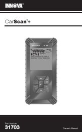
About the <strong>Car</strong> <strong>Reader</strong>CONTROLS AND INDICATORSCONTROLS AND INDICATORS75416328Figure 1. Controls and IndicatorsSee Figure 1 for the locations of items 1 through 9, below.1. ERASE button - Erases Diagnostic Trouble Codes (DTCs) and "FreezeFrame" data from your vehicle's computer, and resets Monitor status.2. SCROLL button - Scrolls the LCD display to view DTCs when more thanone DTC is present.3. LINK button - Links the <strong>Car</strong> <strong>Reader</strong> with the vehicle's PCM to retrieveDTCs from the computer's memory, and to view I/M Readiness Monitorstatus.4. GREEN LED - Indicates that all engine systems are running normally (allMonitors on the vehicle are active and performing their diagnostic testing, andno DTCs are present).5. YELLOW LED - Indicates there is a possible problem. A “Pending” DTCis present and/or some of the vehicle's emission monitors have not run theirdiagnostic testing.4 OBD2
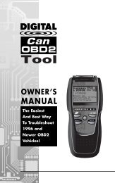
About the <strong>Car</strong> <strong>Reader</strong>DISPLAY FUNCTIONS6. RED LED - Indicates there is a problem in one or more of the vehicle'ssystems. The red LED is also used to show that DTC(s) are present. DTCsare shown on the <strong>Car</strong> <strong>Reader</strong>’s LCD display. In this case, the MultifunctionIndicator (“Check Engine”) lamp on the vehicle's instrument panel will lightsteady on.7. LCD Display - Displays test results, <strong>Car</strong> <strong>Reader</strong> functions and Monitor statusinformation. See DISPLAY FUNCTIONS, below, for details.8. CABLE - Connects the <strong>Car</strong> <strong>Reader</strong> to the vehicle's Data Link Connector(DLC).DISPLAY FUNCTIONS10 5 4 6128973Figure 2. Display FunctionsSee Figure 2 for the locations of items 1 through 13, below.1. Vehicle icon - Indicates whether or not the <strong>Car</strong> <strong>Reader</strong> is being properlypowered through the vehicle's Data Link Connector (DLC). A visible iconindicates that the <strong>Car</strong> <strong>Reader</strong> is being powered through the vehicle's DLCconnector.2. Link icon - Indicates whether or not the <strong>Car</strong> <strong>Reader</strong> is communicating(linked) with the vehicle's on-board computer. When visible, the <strong>Car</strong> <strong>Reader</strong>is communicating with the computer. If the Link icon is not visible, the <strong>Car</strong><strong>Reader</strong> is not communicating with the computer.3. DTC Display Area - Displays the Diagnostic Trouble Code (DTC) number.Each fault is assigned a code number that is specific to that fault.4. Pending icon - Indicates the currently displayed DTC is a "Pending" code.5. CODE icon - Identifies the Code Number Sequence display area.6. MIL icon - Indicates the status of the Malfunction Indicator Lamp (MIL). TheMIL icon is visible only when a DTC has commanded the MIL on the vehicle'sdashboard to light.7. FREEZE FRAME icon - Indicates that “Freeze Frame” data has been storedin the vehicle’s computer for the currently displayed DTC.OBD2 5
About the <strong>Car</strong> <strong>Reader</strong>DISPLAY FUNCTIONS8. Code Number Sequence - The <strong>Car</strong> <strong>Reader</strong> assigns a sequence number toeach DTC that is present in the computer's memory, starting with "01.” Thishelps keep track of the number of DTCs present in the computer's memory.Code number "01" is always the highest priority code, and the one for which"Freeze Frame" data has been stored.9. Code Enumerator - Indicates the total number of codes retrieved from thevehicle’s computer.10. Monitor icons - Indicates which Monitors are supported by the vehicleunder test, and whether or not the associated Monitor has run its diagnostictesting (Monitor status). When a Monitor icon is solid, it indicates that theassociated Monitor has completed its diagnostic testing. When a Monitoricon is flashing, it indicates that the vehicle supports the associated Monitor,but the Monitor has not yet run its diagnostic testing.The I/M Monitor Status icons are associated with INSPECTION andMAINTENANCE (I/M) READINESS STATUS. Some states require thatall vehicle Monitors have run and completed their diagnostic testingbefore a vehicle can be tested for Emissions (Smog Check). Amaximum of eleven Monitors are used on OBD 2 systems. Not allvehicles support all eleven Monitors. When the <strong>Car</strong> <strong>Reader</strong> is linked toa vehicle, only the icons for Monitors that are supported by the vehicleunder test are visible on the display.Following is a list of Monitor icons and their associated Monitors.= Misfire Monitor= Fuel System Monitor= Comprehensive Component Monitor= Catalyst Monitor= Heated Catalyst Monitor= Evaporative System Monitor= Secondary Air System Monitor= Air Conditioning System Refrigerant (R-12) Monitor= Oxygen Sensor Monitor= Oxygen Sensor Heater Monitor= Exhaust Gas Recirculation (EGR) Monitor6 OBD2
Preparation for TestingBEFORE YOU BEGIN / VEHICLE SERVICE MANUALSBEFORE YOU BEGINFix any known mechanical problems before performing any test. See yourvehicle's service manual or a mechanic for more information. Check thefollowing areas before starting any test:■ Check the engine oil, power steering fluid, transmission fluid (ifapplicable), engine coolant and other fluids for proper levels. Top off lowfluid levels if needed.■ Make sure the air filter is clean and in good condition. Make sure all air filterducts are properly connected. Check the air filter ducts for holes, rips or cracks.■ Make sure all engine belts are in good condition. Check for cracked, torn,brittle, loose or missing belts.■ Make sure mechanical linkages to engine sensors (throttle, gearshift position,transmission, etc.) are secure and properly connected. See your vehicle'sservice manual for locations.■ Check all rubber hoses (radiator) and steel hoses (vacuum/fuel) for leaks,cracks, blockage or other damage. Make sure all hoses are routed andconnected properly.■ Make sure all spark plugs are clean and in good condition. Check fordamaged, loose, disconnected or missing spark plug wires.■ Make sure the battery terminals are clean and tight. Check for corrosion orbroken connections. Check for proper battery and charging system voltages.■ Check all electrical wiring and harnesses for proper connection. Make surewire insulation is in good condition, and there are no bare wires.■ Make sure the engine is mechanically sound. If needed, perform acompression check, engine vacuum check, timing check (if applicable), etc.VEHICLE SERVICE MANUALSAlways refer to the manufacturer's service manual for your vehicle beforeperforming any test or repair procedures. Contact your local car dealership, autoparts store or bookstore for availability of these manuals. The followingcompanies publish valuable repair manuals:■ Haynes Publications - 861 Lawrence Drive, Newbury Park, California91320 Phone: 800-442-9637■ Mitchell International - 14145 Danielson Street, Poway, California 92064Phone: 888-724-6742■ Motor Publications - 5600 Crooks Road, Suite 200 , Troy, Michigan 48098Phone: 800-426-6867FACTORY SOURCESFord, GM, Chrysler, Honda, Isuzu, Hyundai and Subaru Service Manuals■ Helm Inc.- -14310 Hamilton Avenue, Highland Park, Michigan 48203Phone: 800-782-4356OBD2 7
Using the <strong>Car</strong> <strong>Reader</strong>CODE RETRIEVAL PROCEDURECODE RETRIEVAL PROCEDURENever replace a part based only on the DTC definition. Each DTC has a set oftesting procedures, instructions and flow charts that must be followed to confirm thelocation of the problem. This information is found in the vehicle's service manual.Always refer to the vehicle's service manual for detailed testing instructions.Check your vehicle thoroughly before performing any test. SeePreparation for Testing on page 7 for details.ALWAYS observe safety precautions whenever working on a vehicle.See Safety Precautions on page 2 for more information.1. Turn the ignition off.2. Locate the vehicle's 16-pin Data Link Connector(DLC). See page 3 for connector location.3. Connect the <strong>Car</strong> <strong>Reader</strong>’s cable connector to thevehicle's DLC. The cable connector is keyed andwill only fit one way.■ If you have problems connecting the cableconnector to the DLC, rotate the connector180° and try again.If you still have problems, check the DLC onthe vehicle and on the <strong>Car</strong> <strong>Reader</strong>. Refer toyour vehicle's service manual to properly checkthe vehicle's DLC.■ After the <strong>Car</strong> <strong>Reader</strong>’s test connector is properly connected to thevehicle's DLC, the Vehicle icon should display to confirm a goodpower connection.4. Turn the ignition on. DO NOT start the engine.5. The <strong>Car</strong> <strong>Reader</strong> will automatically link to the vehicle’s computer.■ The LCD display will show "rEAd.” If the LCDdisplay is blank, it indicates there is no powerat the vehicle's DLC. Check your fuse paneland replace any burned-out fuses.If replacing the fuse(s) does not correct theproblem, see your vehicle's repair manual tolocate the proper computer (PCM) fuse/circuit.Perform any necessary repairs beforecontinuing.■ After 4-5 seconds, the <strong>Car</strong> <strong>Reader</strong> will retrieveand display any Diagnostic Trouble Codes thatare in the vehicle's computer memory.■ If an error message (Err, Err1 or Err2) isshown on the <strong>Car</strong> <strong>Reader</strong>’s LCD display, itindicates there is a communication problem.This means that the <strong>Car</strong> <strong>Reader</strong> is unable tocommunicate with the vehicle's computer. Dothe following:8 OBD2
CODE RETRIEVAL PROCEDUREUsing the <strong>Car</strong> <strong>Reader</strong>- Turn the ignition key off, wait 5 seconds and turn the key back on toreset the computer.- Make sure your vehicle is OBD 2 compliant. See VEHICLES COVEREDon page 2 for vehicle compliance verification information.6. Read and interpret the Diagnostic Trouble Codes using the LCD display andthe green, yellow and red LEDs.The green, yellow and red LEDs are used (with the LCD display) asvisual aids to make it easier for the user to determine engine systemconditions.■ Green LED - Indicates that all enginesystems are "OK" and running normally. Allmonitors on the vehicle are active and areperforming their diagnostic testing, and notrouble codes are present. A zero will show onthe <strong>Car</strong> <strong>Reader</strong>’s LCD display for furtherconfirmation.■ Yellow LED - Indicates one of the followingconditions:PENDING CODE PRESENT - If the yellowLED is lit, it may indicate the existence of apending code. Check the <strong>Car</strong> <strong>Reader</strong>’s LCDdisplay for confirmation. A pending code isconfirmed by the presence of a numeric codeand the word PENDING on the <strong>Car</strong> <strong>Reader</strong>’sLCD display. If no pending code is shown, theyellow LED indicates Monitor Status (see thefollowing).MONITOR STATUS - If the <strong>Car</strong> <strong>Reader</strong>’s LCDdisplay shows a zero (indicating there are noDTCs present in the vehicle's computer), butthe yellow LED is lit, it indicates a "Monitor HasNot Run" status. This means that some of theMonitors on the vehicle have not yet finishedtheir diagnostic self-testing. This condition isconfirmed by one or more blinking Monitoricons on the LCD display. A blinking Monitoricon means the Monitor has not yet run andfinished its diagnostic self-testing. All Monitoricons that are solid have completed theirdiagnostic self-testing.■ Red LED - Indicates there is a problem withone or more of the vehicle's systems. The redLED is also used to show that DTC(s) arepresent (displayed on the <strong>Car</strong> <strong>Reader</strong>’s LCDdisplay). In this case, the Multifunction Indicator(Check Engine) lamp on the vehicle's instrumentpanel will light steady on.OBD2 9
Using the <strong>Car</strong> <strong>Reader</strong>ERASING DIAGNOSTIC TROUBLE CODES (DTCs)The <strong>Car</strong> <strong>Reader</strong> will automatically re-link to the vehicle'scomputer every 15 seconds to refresh the data being retrieved.When data is being refreshed, a single beep will sound, and"rEAd" will be shown on the LCD display for 5-6 seconds. The<strong>Car</strong> <strong>Reader</strong> will then beep twice and return to displaying codes.This action repeats as long as the <strong>Car</strong> <strong>Reader</strong> is in communicationwith the vehicle's computer.The <strong>Car</strong> <strong>Reader</strong> will display a code only if codes are present inthe vehicle's computer memory. If no codes are present, a "0" willbe displayed.7. If more than one code is present, press and release the SCROLL button,as necessary, to display additional codes.■ Whenever the SCROLL function is used to view additional codes, the <strong>Car</strong><strong>Reader</strong>’s communication link with the vehicle's computer disconnects. Tore-establish communication, press the LINK button again.Refer to page 14 for Diagnostic Trouble Code definitions. Match the retrievedDTC(s) with those listed. Read the associated definition(s), and see the vehicle'sservice manual for further evaluation.ERASING DIAGNOSTIC TROUBLE CODES (DTCs)When the <strong>Car</strong> <strong>Reader</strong>’s ERASE function is used to erase the DTCsfrom the vehicle's on-board computer, "Freeze Frame" data andmanufacturer-specific enhanced data are also erased.If you plan to take the vehicle to a Service Center for repair, DO NOT erase thecodes from the vehicle's computer. If the codes are erased, valuable informationthat might help the technician troubleshoot the problem will also be erased.Erase DTCs from the computer's memory as follows:When DTCs are erased from the vehicle's computer memory, the I/MReadiness Monitor Status program resets status of all the Monitors toa not run "flashing" condition. To set all of the Monitors to a DONEstatus, an OBD 2 Drive Cycle must be performed. Refer to yourvehicle's service manual for information on how to perform an OBD 2Drive Cycle for the vehicle under test.1. If not connected already, connect the <strong>Car</strong> <strong>Reader</strong>to the vehicle's DLC. (If the <strong>Car</strong> <strong>Reader</strong> is alreadyconnected and linked to the vehicle's computer,proceed directly to step 4. If not, continue to step2.)2. Turn the ignition on. DO NOT start the engine. The<strong>Car</strong> <strong>Reader</strong> will automatically link to the vehicle’scomputer.10 OBD2
Using the <strong>Car</strong> <strong>Reader</strong>ERASING DIAGNOSTIC TROUBLE CODES (DTCs)3. Press and release the <strong>Car</strong> <strong>Reader</strong>’s ERASEbutton. The LCD display will indicate "SurE" foryour confirmation.■ If you change your mind and do not wish toerase the codes, press the LINK button toreturn to the code retrieval function.■ If you wish to continue, press the ERASEbutton again. When all retrievable information,including DTCs, has been cleared from thecomputer’s memory, the <strong>Car</strong> <strong>Reader</strong> will re-linkto the vehicle’s computer, and the LCD displaywill show "rEAd.”Erasing DTCs does not fix the problem(s) that caused the code(s) tobe set. If proper repairs to correct the problem that caused the code(s)to be set are not made, the code(s) will appear again (and the checkengine light will illuminate) as soon as the vehicle is driven long enoughfor its Monitors to complete their testing.OBD2 11
DTC DefinitionsDIAGNOSTIC TROUBLE CODE DEFINITIONSDIAGNOSTIC TROUBLE CODE DEFINITIONSDiagnostic Trouble Codes (DTCs) are meant to guide you to the proper serviceprocedure in the vehicle's service manual. DO NOT replace parts based only onDTCs without first consulting the vehicle's service manual for proper testingprocedures for that particular system, circuit or component.DTCs are alphanumeric codes that are used to identify a problem that is presentin any of the systems that are monitored by the on-board computer (PCM). Eachtrouble code has an assigned message that identifies the circuit, component orsystem area where the problem was found.OBD 2 diagnostic trouble codes are made up of five characters:■ The 1st character is a letter. It identifies the "main system" where the faultoccurred (Body, Chassis, Powertrain, or Network).■ The 2nd character is a numeric digit. It identifies the "type" of code (Genericor Manufacturer-Specific).Generic DTCs are codes that are used by all vehicle manufacturers.The standards for generic DTCs, as well as their definitions, are set bythe Society of Automotive Engineers (SAE).Manufacturer-Specific DTCs are codes that are controlled by thevehicle manufacturer. The Federal Government does not requiremanufacturer-specific codes in order to comply with the new OBD 2emissions standards. However, manufacturers are free to expandbeyond the required codes to make their systems easier to diagnose.■ The 3rd character is a numeric digit. It identifies the specific system or subsystemwhere the problem is located.■ The 4th and 5th characters are numeric digits. They identify the section ofthe system that is malfunctioning.This section provides the most complete list of “Generic” DTC definitionsavailable at the time of publication. OBD 2 is an evolving system; new codes anddefinitions are added as the system grows. ALWAYS check your vehicle'sservice manual for code definitions that are not listed here, or for “Manufacturer-Specific” DTC definitions. For more information, visit our web site atwww.Code<strong>Reader</strong>.com.12 OBD2
DIAGNOSTIC TROUBLE CODE DEFINITIONSDTC DefinitionsOBD 2 DTC EXAMPLEP0201 - Injector Circuit Malfunction, Cylinder 1BCPU- Body---ChassisPowertrainNetworkP 0 2 0 10123----GenericManufacturer SpecificGenericIncludes both Generic and ManufacturerSpecific CodesIdentifies the system where theproblem is located:12345678--------Fuel and Air MeteringFuel and Air Metering (injector circuitmalfunction only)Ignition System or MisfireAuxiliary Emission Control SystemVehicle Speed Control and Idle ControlSystemComputer Output CircuitsTransmissionTransmissionIdentifies what section of the systemis malfunctioningOBD2 13
DTC DefinitionsP0010 - P0075CodeDefinitionP0010 "A" Camshaft Position - Actuator Circuit (Bank 1)P0011 "A" Camshaft Position - Timing Over-Advanced or System Performance (Bank 1)P0012 "A" Camshaft Position - Timing Over-Retarded (Bank 1)P0013 "B" Camshaft Position - Actuator Circuit (Bank 1)P0014 "B" Camshaft Position - Timing Over-Advanced or System Performance (Bank 1)P0015 "B" Camshaft Position - Timing Over-Retarded (Bank 1)P0020 "A" Camshaft Position - Actuator Circuit (Bank 2)P0021 "A" Camshaft Position - Timing Over-Advanced or System Performance (Bank 2)P0022 "A" Camshaft Position - Timing Over-Retarded (Bank 2)P0023 "B" Camshaft Position - Actuator Circuit (Bank 2)P0024 "B" Camshaft Position - Timing Over-Advanced or System Performance (Bank 2)P0025 "B" Camshaft Position - Timing Over-Retarded (Bank 2)P0030 HO2S Heater Control Circuit (Bank 1 Sensor 1)P0031 HO2S Heater Control Circuit Low (Bank 1 Sensor 1)P0032 HO2S Heater Control Circuit High (Bank 1 Sensor 1)P0033 Turbo Charger Bypass Valve Control CircuitP0034 Turbo Charger Bypass Valve Control Circuit LowP0035 Turbo Charger Bypass Valve Control Circuit HighP0036 HO2S Heater Control Circuit (Bank 1 Sensor 2)P0037 HO2S Heater Control Circuit Low (Bank 1 Sensor 2)P0038 HO2S Heater Control Circuit High (Bank 1 Sensor 2)P0042 HO2S Heater Control Circuit (Bank 1 Sensor 3)P0043 HO2S Heater Control Circuit Low (Bank 1 Sensor 3)P0044 HO2S Heater Control Circuit High (Bank 1 Sensor 3)P0050 HO2S Heater Control Circuit (Bank 2 Sensor 1)P0051 HO2S Heater Control Circuit Low (Bank 2 Sensor 1)P0052 HO2S Heater Control Circuit High (Bank 2 Sensor 1)P0056 HO2S Heater Control Circuit (Bank 2 Sensor 2)P0057 HO2S Heater Control Circuit Low (Bank 2 Sensor 2)P0058 HO2S Heater Control Circuit High (Bank 2 Sensor 2)P0062 HO2S Heater Control Circuit (Bank 2 Sensor 3)P0063 HO2S Heater Control Circuit Low (Bank 2 Sensor 3)P0064 HO2S Heater Control Circuit High (Bank 2 Sensor 3)P0065 Air Assisted Injector Control Range/PerformanceP0066 Air Assisted Injector Control Circuit or Circuit LowP0067 Air Assisted Injector Control Circuit HighP0070 Ambient Air Temperature Sensor CircuitP0071 Ambient Air Temperature Sensor Range/PerformanceP0072 Ambient Air Temperature Sensor Circuit Low InputP0073 Ambient Air Temperature Sensor Circuit High InputP0074 Ambient Air Temperature Sensor Circuit IntermittentP0075 Intake Valve Control Solenoid Circuit (Bank 1)14 OBD2
P0076 - P0128DTC DefinitionsCodeDefinitionP0076 Intake Valve Control Solenoid Circuit Low (Bank 1)P0077Intake Valve Control Solenoid Circuit High (Bank 1)P0078Exhaust Valve Control Solenoid Circuit (Bank 1)P0079Exhaust Valve Control Solenoid Circuit Low (Bank 1)P0080Exhaust Valve Control Solenoid Circuit High (Bank 1)P0081Intake Valve Control Solenoid Circuit (Bank 2)P0082Intake Valve Control Solenoid Circuit Low (Bank 2)P0083Intake Valve Control Solenoid Circuit High (Bank 2)P0084Exhaust Valve Control Solenoid Circuit (Bank 2)P0085Exhaust Valve Control Solenoid Circuit Low (Bank 2)P0086Exhaust Valve Control Solenoid Circuit High (Bank 2)P0100Mass or Volume Air Flow Circuit MalfunctionP0101Mass or Volume Circuit Range Performance ProblemP0102Mass or Volume Circuit Low InputP0103Mass or Volume Circuit High InputP0104Mass or Volume Circuit IntermittentP0105Manifold Absolute Pressure/Barometric Pressure Circuit MalfunctionP0106Manifold Absolute Pressure/Barometric Pressure CircuitRange/PerformanceProblP0107Manifold Absolute Pressure/Barometric Pressure Circuit Low InputP0108Manifold Absolute Pressure/Barometric Pressure Circuit High InputP0109Manifold Absolute Pressure/Barometric Pressure Circuit IntermittentP0110Intake Air Temperature Circuit MalfunctionP0111Intake Air Temperature Circuit Range/Performance ProblemP0112Intake Air Temperature Circuit Low InputP0113Intake Air Temperature Circuit High InputP0114Intake Air Temperature Circuit IntermittentP0115Engine Coolant Temperature Circuit MalfunctionP0116Engine Coolant Temperature Circuit Range/Performance ProblemP0117Engine Coolant Temperature Circuit Low InputP0118Engine Coolant Temperature Circuit High InputP0119Engine Coolant Temperature Circuit IntermittentP0120Throttle/Pedal Position Sensor/Switch A Circuit MalfunctionP0121Throttle/Pedal Position Sensor/Switch A Circuit Range/Performance ProblemP0122Throttle/Pedal Position Sensor/Switch A Circuit Low InputP0123Throttle/Pedal Position Sensor/Switch A Circuit High InputP0124Throttle/Pedal Position Sensor/Switch A Circuit IntermittentP0125Insufficient Coolant Temperature for Closed Loop FuelContP0126Insufficient Coolant Temperature for Stable OperationP0127Intake Air Temperature Too HighP0128Coolant Thermostat (Coolant Temperature Below Thermostat RegulatingTemperatOBD2 15
P0172 - P0213DTC DefinitionsCodeDefinitionP0172 System too Rich (Bank 1)P0173 Fuel Trim Malfunction (Bank 2)P0174 System too Lean (Bank 2)P0175 System too Rich (Bank 2)P0176 Fuel Composition Sensor Circuit MalfunctionP0177 Fuel Composition Sensor Circuit Range/PerformanceP0178 Fuel Composition Sensor Circuit Low InputP0179 Fuel Composition Sensor Circuit High InputP0180 Fuel Temperature Sensor A Circuit MalfunctionP0181 Fuel Temperature Sensor A Circuit Range/PerformanceP0182 Fuel Temperature Sensor A Circuit Low InputP0183 Fuel Temperature Sensor A Circuit High InputP0184 Fuel Temperature Sensor A Circuit IntermittentP0185 Fuel Temperature Sensor B Circuit MalfunctionP0186 Fuel Temperature Sensor B Circuit Range/PerformanceP0187 Fuel Temperature Sensor B Circuit Low InputP0188 Fuel Temperature Sensor B Circuit High InputP0189 Fuel Temperature Sensor B Circuit IntermittentP0190 Fuel Rail Pressure Sensor Circuit MalfunctionP0191 Fuel Rail Pressure Sensor Circuit Range/PerformanceP0192 Fuel Rail Pressure Sensor Circuit Low InputP0193 Fuel Rail Pressure Sensor Circuit High InputP0194 Fuel Rail Pressure Sensor Circuit IntermittentP0195 Engine Oil Temperature Sensor MalfunctionP0196 Engine Oil Temperature Sensor Range/PerformanceP0197 Engine Oil Temperature Sensor LowP0198 Engine Oil Temperature Sensor HighP0199 Engine Oil Temperature Sensor IntermittentP0200 Injector Circuit MalfunctionP0201 Injector Circuit Malfunction - Cylinder 1P0202 Injector Circuit Malfunction - Cylinder 2P0203 Injector Circuit Malfunction - Cylinder 3P0204 Injector Circuit Malfunction - Cylinder 4P0205 Injector Circuit Malfunction - Cylinder 5P0206 Injector Circuit Malfunction - Cylinder 6P0207 Injector Circuit Malfunction - Cylinder 7P0208 Injector Circuit Malfunction - Cylinder 8P0209 Injector Circuit Malfunction - Cylinder 9P0210 Injector Circuit Malfunction - Cylinder 10P0211 Injector Circuit Malfunction - Cylinder 11P0212 Injector Circuit Malfunction - Cylinder 12P0213 Cold Start Injector 1 MalfunctionOBD2 17
DTC DefinitionsP0214 - P0255CodeP0214P0215P0216P0217P0218P0219P0220P0221P0222P0223P0224P0225P0226P0227P0228P0229P0230P0231P0232P0233P0234P0235P0236P0237P0238P0239P0240P0241P0242P0243P0244P0245P0246P0247P0248P0249P0250P0251P0252P0253P0254P0255DefinitionCold Start Injector 2 MalfunctionEngine Shutoff Solenoid MalfunctionInjection Timing Control Circuit MalfunctionEngine Overtemp ConditionTransmission Over Temperature ConditionEngine Overspeed ConditionThrottle/Pedal Position Sensor/Switch B Circuit MalfunctionThrottle/Pedal Position Sensor/Switch B Circuit Range/Performance ProblemThrottle/Pedal Position Sensor/Switch B Circuit Low InputThrottle/Pedal Position Sensor/Switch B Circuit High InputThrottle/Pedal Position Sensor/Switch B Circuit IntermittentThrottle/Pedal Position Sensor/Switch C Circuit MalfunctionThrottle/Pedal Position Sensor/Switch C Circuit Range/Performance ProblemThrottle/Pedal Position Sensor/Switch C Circuit Low InputThrottle/Pedal Position Sensor/Switch C Circuit High InputThrottle/Pedal Position Sensor/Switch C Circuit IntermittentFuel Pump Primary Circuit MalfunctionFuel Pump Secondary Circuit LowFuel Pump Secondary Circuit HighFuel Pump Secondary Circuit IntermittentEngine Overboost ConditionTurbocharger Boost Sensor A Circuit MalfunctionTurbocharger Boost Sensor A Circuit Range/PerformanceTurbocharger Boost Sensor A Circuit LowTurbocharger Boost Sensor A Circuit HighTurbocharger Boost Sensor B Circuit MalfunctionTurbocharger Boost Sensor B Circuit Range/PerformanceTurbocharger Boost Sensor B Circuit LowTurbocharger Boost Sensor B Circuit HighTurbocharger Wastegate Solenoid A MalfunctionTurbocharger Wastegate Solenoid A Range/PerformanceTurbocharger Wastegate Solenoid A LowTurbocharger Wastegate Solenoid A HighTurbocharger Wastegate Solenoid B MalfunctionTurbocharger Wastegate Solenoid B Range/PerformanceTurbocharger Wastegate Solenoid B LowTurbocharger Wastegate Solenoid B HighInjection Pump A Rotor/Cam MalfunctionInjection Pump A Rotor/Cam Range/PerformanceInjection Pump A Rotor/Cam LowInjection Pump A Rotor/Cam HighInjection Pump A Rotor/Cam Intermitted18 OBD2
DTC DefinitionsP0300 - P0346CodeDefinitionP0300 Random/Multiple Cylinder Misfire DetectedP0301 Cylinder 1 Misfire DetectedP0302 Cylinder 2 Misfire DetectedP0303 Cylinder 3 Misfire DetectedP0304 Cylinder 4 Misfire DetectedP0305 Cylinder 5 Misfire DetectedP0306 Cylinder 6 Misfire DetectedP0307 Cylinder 7 Misfire DetectedP0308 Cylinder 8 Misfire DetectedP0309 Cylinder 9 Misfire DetectedP0310 Cylinder 10 Misfire DetectedP0311 Cylinder 11 Misfire DetectedP0312 Cylinder 12 Misfire DetectedP0313 Misfire Detected with Low FuelP0314 Single Cylinder Misfire (Cylinder not specified)P0320 Ignition/Distributor Engine Speed Input Circuit MalfunctionP0321 Ignition/Distributor Engine Speed Input Circuit Range/PerformanceP0322 Ignition/Distributor Engine Speed Input Circuit No SignalP0323 Ignition/Distributor Engine Speed Input Circuit IntermittentP0324 Knock Control System ErrorP0325 Knock Sensor 1 Circuit Malfunction (Bank 1 or Single Sensor)P0326 Knock Sensor 1 Circuit Range/Performance (Bank 1 or Single Sensor)P0327 Knock Sensor 1 Circuit Low Input (Bank 1 or Single Sensor)P0328 Knock Sensor 1 Circuit High Input (Bank 1 or Single Sensor)P0329 Knock Sensor 1 Circuit Intermittent (Bank 1 or Single Sensor)P0330 Knock Sensor 2 Circuit Malfunction (Bank 2)P0331 Knock Sensor 2 Circuit Range/Performance (Bank 2)P0332 Knock Sensor 2 Circuit Low Input (Bank 2)P0333 Knock Sensor 2 Circuit High Input (Bank 2)P0334 Knock Sensor 2 Circuit Intermittent (Bank 2)P0335 Crankshaft Position Sensor A Circuit MalfunctionP0336 Crankshaft Position Sensor A Circuit Range/PerformanceP0337 Crankshaft Position Sensor A Circuit Low InputP0338 Crankshaft Position Sensor A Circuit High InputP0339 Crankshaft Position Sensor A Circuit IntermittentP0340 Camshaft Position Sensor Circuit MalfunctionP0341 Camshaft Position Sensor Circuit Range/PerformanceP0342 Camshaft Position Sensor Circuit Low InputP0343 Camshaft Position Sensor Circuit High InputP0344 Camshaft Position Sensor Circuit IntermittentP0345 Camshaft Position Sensor "A" Circuit (Bank 2)P0346 Camshaft Position Sensor "A" Circuit Range/Performance (Bank 2)20 OBD2
P0347 - P0392DTC DefinitionsCodeDefinitionP0347 Camshaft Position Sensor "A" Circuit Low Input (Bank 2)P0348 Camshaft Position Sensor "A" Circuit High Input (Bank 2)P0349 Camshaft Position Sensor "A" Circuit Intermittent (Bank 2)P0350 Ignition Coil Primary/Secondary Circuit MalfunctionP0351 Ignition Coil A Primary/Secondary Circuit MalfunctionP0352 Ignition Coil B Primary/Secondary Circuit MalfunctionP0353 Ignition Coil C Primary/Secondary Circuit MalfunctionP0354 Ignition Coil D Primary/Secondary Circuit MalfunctionP0355 Ignition Coil E Primary/Secondary Circuit MalfunctionP0356 Ignition Coil F Primary/Secondary Circuit MalfunctionP0357 Ignition Coil G Primary/Secondary Circuit MalfunctionP0358 Ignition Coil H Primary/Secondary Circuit MalfunctionP0359 Ignition Coil I Primary/Secondary Circuit MalfunctionP0360 Ignition Coil J Primary/Secondary Circuit MalfunctionP0361 Ignition Coil K Primary/Secondary Circuit MalfunctionP0362 Ignition Coil L Primary/Secondary Circuit MalfunctionP0365 Camshaft Position Sensor "B" Circuit (Bank 1)P0366 Camshaft Position Sensor "B" Circuit Range/Performance (Bank 1)P0367 Camshaft Position Sensor "B" Circuit Low Input (Bank 1)P0368 Camshaft Position Sensor "B" Circuit High Input (Bank 1)P0369 Camshaft Position Sensor "B" Circuit Intermittent (Bank 1)P0370 Timing Reference High Resolution Signal A MalfunctionP0371 Timing Reference High Resolution Signal A Too Many PulsesP0372 Timing Reference High Resolution Signal A Too Few PulsesP0373 Timing Reference High Resolution Signal A Intermittent/Erratic PulsesP0374 Timing Reference High Resolution Signal A No PulsesP0375 Timing Reference High Resolution Signal B MalfunctionP0376 Timing Reference High Resolution Signal B Too Many PulsesP0377 Timing Reference High Resolution Signal B Too Few PulsesP0378 Timing Reference High Resolution Signal B Intermittent/Erratic PulsesP0379 Timing Reference High Resolution Signal B No PulsesP0380 Glow Plug/Heater Circuit MalfunctionP0381 Glow Plug/Heater Indicator Circuit MalfunctionP0382 Glow Plug/Heater Circuit "B" MalfunctionP0385 Crankshaft Position Sensor B Circuit MalfunctionP0386 Crankshaft Position Sensor B Circuit Range/PerformanceP0387 Crankshaft Position Sensor B Circuit Low InputP0388 Crankshaft Position Sensor B Circuit High InputP0389 Crankshaft Position Sensor B Circuit IntermittentP0390 Camshaft Position Sensor "B" Circuit (Bank 2)P0391 Camshaft Position Sensor "B" Circuit Range/Performance (Bank 2)P0392 Camshaft Position Sensor "B" Circuit Low Input (Bank 2)OBD2 21
DTC DefinitionsP0393 - P0439CodeDefinitionP0393 Camshaft Position Sensor "B" Circuit High Input (Bank 2)P0394 Camshaft Position Sensor "B" Circuit Intermittent (Bank 2)P0400 Exhaust Gas Recirculation Flow MalfunctionP0401 Exhaust Gas Recirculation Flow Insufficient DetectedP0402 Exhaust Gas Recirculation Flow Excessive DetectedP0403 Exhaust Gas Recirculation Circuit MalfunctionP0404 Exhaust Gas Recirculation Circuit Range/PerformanceP0405 Exhaust Gas Recirculation Sensor A Circuit LowP0406 Exhaust Gas Recirculation Sensor A Circuit HighP0407 Exhaust Gas Recirculation Sensor B Circuit LowP0408 Exhaust Gas Recirculation Sensor B Circuit HighP0409 Exhaust Gas Recirculation Sensor "A" CircuitP0410 Secondary Air Injection System MalfunctionP0411 Secondary Air Injection System Incorrect Flow DetectedP0412 Secondary Air Injection System Switching Valve A Circuit MalfunctionP0413 Secondary Air Injection System Switching Valve A Circuit OpenP0414 Secondary Air Injection System Switching Valve A Circuit ShortedP0415 Secondary Air Injection System Switching Valve B Circuit MalfunctionP0416 Secondary Air Injection System Switching Valve B Circuit OpenP0417 Secondary Air Injection System Switching Valve B Circuit ShortedP0418 Secondary Air Injection System Relay "A" Circuit MalfunctionP0419 Secondary Air Injection System Relay "B" Circuit MalfunctionP0420 Catalyst System Efficiency Below Threshold (Bank 1)P0421 Warm Up Catalyst Efficiency Below Threshold (Bank 1)P0422 Main Catalyst Efficiency Below Threshold (Bank 1)P0423 Heated Catalyst Efficiency Below Threshold (Bank 1)P0424 Heated Catalyst Temperature Below Threshold (Bank 1)P0425 Catalyst Temperature Sensor (Bank 1)P0426 Catalyst Temperature Sensor Range/Performance (Bank 1)P0427 Catalyst Temperature Sensor Low Input (Bank 1)P0428 Catalyst Temperature Sensor High Input (Bank 1)P0429 Catalyst Heater Control Circuit (Bank 1)P0430 Catalyst System Efficiency Below Threshold (Bank 2)P0431 Warm Up Catalyst Efficiency Below Threshold (Bank 2)P0432 Main Catalyst Efficiency Below Threshold (Bank 2)P0433 Heated Catalyst Efficiency Below Threshold (Bank 2)P0434 Heated Catalyst Temperature Below Threshold (Bank 2)P0435 Catalyst Temperature Sensor (Bank 2)P0436 Catalyst Temperature Sensor Range/Performance (Bank 2)P0437 Catalyst Temperature Sensor Low Input (Bank 2)P0438 Catalyst Temperature Sensor High Input (Bank 2)P0439 Catalyst Heater Control Circuit (Bank 2)22 OBD2
P0440 - P0483DTC DefinitionsCodeP0440P0441P0442P0443P0444P0445P0446P0447P0448P0449P0450P0451P0452P0453P0454P0455P0456P0457P0460P0461P0462P0463P0464P0465P0466P0467P0468P0469P0470P0471P0472P0473P0474P0475P0476P0477P0478P0479P0480P0481P0482P0483DefinitionEvaporative Emission Control System MalfunctionEvaporative Emission Control System Incorrect Purge FlowEvaporative Emission Control System Leak Detected (small leak)Evaporative Emission Control System Purge Control Valve Circuit MalfunctionEvaporative Emission Control System Purge Control Valve Circuit OpenEvaporative Emission Control System Purge Control Valve Circuit ShortedEvaporative Emission Control System Vent Control Circuit MalfunctionEvaporative Emission Control System Vent Control OpenEvaporative Emission Control System Vent Control Circuit ShortedEvaporative Emission Control System Vent Valve/Solenoid Circuit MalfunctionEvaporative Emission Control System Pressure Sensor MalfunctionEvaporative Emission Control System Pressure Sensor Range/PerformanceEvaporative Emission Control System Pressure Sensor Low InputEvaporative Emission Control System Pressure Sensor High InputEvaporative Emission Control System Pressure Sensor IntermittentEvaporative Emission Control System Leak Detected (gross leak)Evaporative Emission Control System Leak Detected (very small leak)Evaporative Emission Control System Leak Detected (fuel cap loose/off)Fuel Level Sensor Circuit MalfunctionFuel Level Sensor Circuit Range/PerformanceFuel Level Sensor Circuit Low InputFuel Level Sensor Circuit High InputFuel Level Sensor Circuit IntermittentPurge Flow Sensor Circuit MalfunctionPurge Flow Sensor Circuit Range/PerformancePurge Flow Sensor Circuit Low InputPurge Flow Sensor Circuit High InputPurge Flow Sensor Circuit IntermittentExhaust Pressure Sensor MalfunctionExhaust Pressure Sensor Range/PerformanceExhaust Pressure Sensor LowExhaust Pressure Sensor HighExhaust Pressure Sensor IntermittentExhaust Pressure Control Valve MalfunctionExhaust Pressure Control Valve Range/PerformanceExhaust Pressure Control Valve LowExhaust Pressure Control Valve HighExhaust Pressure Control Valve IntermittentCooling Fan 1 Control Circuit MalfunctionCooling Fan 2 Control Circuit MalfunctionCooling Fan 3 Control Circuit MalfunctionCooling Fan Rationality Check MalfunctionOBD2 23
DTC DefinitionsP0484 - P0550CodeDefinitionP0484 Cooling Fan Circuit Over CurrentP0485 Cooling Fan Power/Ground Circuit MalfunctionP0486 Exhaust Gas Recirculation Sensor "B" CircuitP0487 Exhaust Gas Recirculation Throttle Position Control CircuitP0488 Exhaust Gas Recirculation Throttle Position Control Range/PerformanceP0491 Secondary Air Injection System (Bank 1)P0492 Secondary Air Injection System (Bank 2)P0500 Vehicle Speed Sensor MalfunctionP0501 Vehicle Speed Sensor Range/PerformanceP0502 Vehicle Speed Sensor Circuit Low InputP0503 Vehicle Speed Sensor Intermittent/Erratic/HighP0505 Idle Control System MalfunctionP0506 Idle Control System RPM Lower Than ExpectedP0507 Idle Control System RPM Higher Than ExpectedP0508 Idle Control System Circuit LowP0509 Idle Control System Circuit HighP0510 Closed Throttle Position Switch MalfunctionP0512 Starter Request CircuitP0513 Incorrect Immobilizer Key ("Immobilizer" pending SAE J1930 approval)P0515 Battery Temperature Sensor CircuitP0516 Battery Temperature Sensor Circuit LowP0517 Battery Temperature Sensor Circuit HighP0520 Engine Oil Pressure/Switch Circuit MalfunctionP0521 Engine Oil Pressure/Switch Range/PerformanceP0522 Engine Oil Pressure/Switch Low VoltageP0523 Engine Oil Pressure/Switch High VoltageP0524 Engine Oil Pressure Too LowP0530 A/C Refrigerant Pressure Sensor Circuit MalfunctionP0531 A/C Refrigerant Pressure Sensor Circuit Range/PerformanceP0532 A/C Refrigerant Pressure Sensor Circuit Low InputP0533 A/C Refrigerant Pressure Sensor Circuit High InputP0534 Air Conditioner Refrigerant Charge LossP0540 Intake Air Heater CircuitP0541 Intake Air Heater Circuit LowP0542 Intake Air Heater Circuit HighP0544 Exhaust Gas Temperature Sensor Circuit (Bank 1)P0545 Exhaust Gas Temperature Sensor Circuit Low (Bank 1)P0546 Exhaust Gas Temperature Sensor Circuit High (Bank 1)P0547 Exhaust Gas Temperature Sensor Circuit (Bank 2)P0548 Exhaust Gas Temperature Sensor Circuit Low (Bank 2)P0549 Exhaust Gas Temperature Sensor Circuit High (Bank 2)P0550 Power Steering Pressure Sensor Circuit Malfunction24 OBD2
P0551 - P0621DTC DefinitionsCodeP0551P0552P0553P0554P0560P0561P0562P0563P0564P0565P0566P0567P0568P0569P0570P0571P0572P0573P0574P0575P0576P0577DefinitionPower Steering Pressure Sensor Circuit Range/PerformancePower Steering Pressure Sensor Circuit Low InputPower Steering Pressure Sensor Circuit High InputPower Steering Pressure Sensor Circuit IntermittentSystem Voltage MalfunctionSystem Voltage UnstableSystem Voltage LowSystem Voltage HighCruise Control Multi-Function Input SignalCruise Control On Signal MalfunctionCruise Control Off Signal MalfunctionCruise Control Resume Signal MalfunctionCruise Control Set Signal MalfunctionCruise Control Coast Signal MalfunctionCruise Control Accel Signal MalfunctionCruise Control/Brake Switch A Circuit MalfunctionCruise Control/Brake Switch A Circuit LowCruise Control/Brake Switch A Circuit HighCruise Control System - Vehicle Speed Too HighCruise Control Input CircuitCruise Control Input Circuit LowCruise Control Input Circuit HighP0578- Reserved for Cruise Control CodesP0580P0600 Serial Communication Link MalfunctionP0601 Internal Control Module Memory Check Sum ErrorP0602 Control Module Programming ErrorP0603 Internal Control Module Keep Alive Memory (KAM) ErrorP0604 Internal Control Module Random Access Memory (RAM) ErrorP0605 Internal Control Module Read Only Memory (ROM) ErrorP0606 PCM Processor FaultP0607 Control Module PerformanceP0608 Control Module VSS Output "A" MalfunctionP0609 Control Module VSS Output "B" MalfunctionP0610 Control Module Vehicle Options ErrorP0615 Starter Relay CircuitP0616 Starter Relay Circuit LowP0617 Starter Relay Circuit HighP0618 Alternative Fuel Control Module KAM ErrorP0619 Alternative Fuel Control Module RAM/ROM ErrorP0620 Generator Control Circuit MalfunctionP0621 Generator Lamp "L" Control Circuit MalfunctionOBD2 25
DTC DefinitionsP0622 - P0715CodeDefinitionP0622 Generator Field "F" Control Circuit MalfunctionP0623 Generator Lamp Control CircuitP0624 Fuel Cap Lamp Control CircuitP0630 VIN Not Programmed or Mismatch - ECM/PCMP0631 VIN Not Programmed or Mismatch - TCMP0635 Power Steering Control CircuitP0636 Power Steering Control Circuit LowP0637 Power Steering Control Circuit HighP0638 Throttle Actuator Control Range/Performance (Bank 1)P0639 Throttle Actuator Control Range/Performance (Bank 2)P0640 Intake Air Heater Control CircuitP0645 A/C Clutch Relay Control CircuitP0646 A/C Clutch Relay Control Circuit LowP0647 A/C Clutch Relay Control Circuit HighP0648 Immobilizer Lamp Control Circuit ("Immobilizer" pending SAE J1930 approval)P0649 Speed Control Lamp Control CircuitP0650 Malfunction Indicator Lamp (MIL) Control Circuit MalfunctionP0654 Engine RPM Output Circuit MalfunctionP0655 Engine Hot Lamp Output Control Circuit MalfunctionP0656 Fuel Level Output Circuit MalfunctionP0660 Intake Manifold Tuning Valve Control Circuit (Bank 1)P0661 Intake Manifold Tuning Valve Control Circuit Low (Bank 1)P0662 Intake Manifold Tuning Valve Control Circuit High (Bank 1)P0663 Intake Manifold Tuning Valve Control Circuit (Bank 2)P0664 Intake Manifold Tuning Valve Control Circuit Low (Bank 2)P0665 Intake Manifold Tuning Valve Control Circuit High (Bank 2)P0700 Transmission Control System MalfunctionP0701 Transmission Control System Range/PerformanceP0702 Transmission Control System ElectricalP0703 Torque Converter/Brake Switch B Circuit MalfunctionP0704 Clutch Switch Input Circuit MalfunctionP0705 Transmission Range Sensor Circuit Malfunction (PRNDL Input)P0706 Transmission Range Sensor Circuit Range/PerformanceP0707 Transmission Range Sensor Circuit Low InputP0708 Transmission Range Sensor Circuit High InputP0709 Transmission Range Sensor Circuit IntermittentP0710 Transmission Fluid Temperature Sensor Circuit MalfunctionP0711 Transmission Fluid Temperature Sensor Circuit Range/PerformanceP0712 Transmission Fluid Temperature Sensor Circuit Low InputP0713 Transmission Fluid Temperature Sensor Circuit High InputP0714 Transmission Fluid Temperature Sensor Circuit IntermittentP0715 Input/Turbine Speed Sensor Circuit Malfunction26 OBD2
P0716 - P0758DTC DefinitionsCodeP0716P0717P0718P0719P0720P0721P0722P0723P0724P0725P0726P0727P0728P0730P0731P0732P0733P0734P0735P0736P0737P0738P0739P0740P0741P0742P0743P0744P0745P0746P0747P0748P0749P0750P0751P0752P0753P0754P0755P0756P0757P0758DefinitionInput/Turbine Speed Sensor Circuit Range/PerformanceInput/Turbine Speed Sensor Circuit No SignalInput/Turbine Speed Sensor Circuit IntermittentTorque Converter/Brake Switch B Circuit LowOutput Speed Sensor Circuit MalfunctionOutput Speed Sensor Circuit Range/PerformanceOutput Speed Sensor Circuit No SignalOutput Speed Sensor Circuit IntermittentTorque Converter/Brake Switch B Circuit HighEngine Speed Input Circuit MalfunctionEngine Speed Input Circuit Range/PerformanceEngine Speed Input Circuit No SignalEngine Speed Input Circuit IntermittentIncorrect Gear RatioGear 1 Incorrect RatioGear 2 Incorrect RatioGear 3 Incorrect RatioGear 4 Incorrect RatioGear 5 Incorrect RatioReverse Incorrect RatioTCM Engine Speed Output CircuitTCM Engine Speed Output Circuit LowTCM Engine Speed Output Circuit HighTorque Converter Clutch Circuit MalfunctionTorque Converter Clutch Circuit Performance or Stuck OffTorque Converter Clutch Circuit Stuck OnTorque Converter Clutch Circuit ElectricalTorque Converter Clutch Circuit IntermittentPressure Control Solenoid MalfunctionPressure Control Solenoid Performance or Stuck OffPressure Control Solenoid Stuck OnPressure Control Solenoid ElectricalPressure Control Solenoid IntermittentShift Solenoid A MalfunctionShift Solenoid A Performance or Stuck OffShift Solenoid A Stuck OnShift Solenoid A ElectricalShift Solenoid A IntermittentShift Solenoid B MalfunctionShift Solenoid B Performance or Stuck OffShift Solenoid B Stuck OnShift Solenoid B ElectricalOBD2 27
DTC DefinitionsP0759 - P0801CodeP0759P0760P0761P0762P0763P0764P0765P0766P0767P0768P0769P0770P0771P0772P0773P0774P0775P0776P0777P0778P0779P0780P0781P0782P0783P0784P0785P0786P0787P0788P0789P0790P0791P0792P0793P0794P0795P0796P0797P0798P0799P0801DefinitionShift Solenoid B IntermittentShift Solenoid C MalfunctionShift Solenoid C Performance or Stuck OffShift Solenoid C Stuck OnShift Solenoid C ElectricalShift Solenoid C IntermittentShift Solenoid D MalfunctionShift Solenoid D Performance or Stuck OffShift Solenoid D Stuck OnShift Solenoid D ElectricalShift Solenoid D IntermittentShift Solenoid E MalfunctionShift Solenoid E Performance or Stuck OffShift Solenoid E Stuck OnShift Solenoid E ElectricalShift Solenoid E IntermittentPressure Control Solenoid "B"Pressure Control Solenoid "B" Performance or Stuck OffPressure Control Solenoid "B" Stuck OnPressure Control Solenoid "B" ElectricalPressure Control Solenoid "B" IntermittentShift Malfunction1-2 Shift Malfunction2-3 Shift Malfunction3-4 Shift Malfunction4-5 Shift MalfunctionShift/Timing Solenoid MalfunctionShift/Timing Solenoid Range/PerformanceShift/Timing Solenoid LowShift/Timing Solenoid HighShift/Timing Solenoid IntermittentNormal/Performance Switch Circuit MalfunctionIntermediate Shaft Speed Sensor CircuitIntermediate Shaft Speed Sensor Circuit Range/PerformanceIntermediate Shaft Speed Sensor Circuit No SignalIntermediate Shaft Speed Sensor Circuit IntermittentPressure Control Solenoid "C"Pressure Control Solenoid "C" Performance or Stuck OffPressure Control Solenoid "C" Stuck OnPressure Control Solenoid "C" ElectricalPressure Control Solenoid "C" IntermittentReverse Inhibit Control Circuit Malfunction28 OBD2
P0803 - P0849DTC DefinitionsCodeP0803P0804P0805P0806P0807P0808P0809P0810P0811P0812P0813P0814P0815P0816P0817P0818P0820P0821P0822P0823P0824P0825P0830P0831P0832P0833P0834P0835P0836P0837P0838P0839P0840P0841P0842P0843P0844P0845P0846P0847P0848P0849Definition1-4 Upshift (Skip Shift) Solenoid Control Circuit Malfunction1-4 Upshift (Skip Shift) Lamp Control Circuit MalfunctionClutch Position Sensor CircuitClutch Position Sensor Circuit Range/PerformanceClutch Position Sensor Circuit LowClutch Position Sensor Circuit HighClutch Position Sensor Circuit IntermittentClutch Position Control ErrorExcessive Clutch SlippageReverse Input CircuitReverse Output CircuitTransmission Range Display CircuitUpshift Switch CircuitDownshift Switch CircuitStarter Disable CircuitDriveline Disconnect Switch Input CircuitGear Lever X-Y Position Sensor CircuitGear Lever X Position CircuitGear Lever Y Position CircuitGear Lever X Position Circuit IntermittentGear Lever Y Position Circuit IntermittentGear Lever Push-Pull Switch (Shift Anticipate)Clutch Pedal Switch "A" CircuitClutch Pedal Switch "A" Circuit LowClutch Pedal Switch "A" Circuit HighClutch Pedal Switch "B" CircuitClutch Pedal Switch "B" Circuit LowClutch Pedal Switch "B" Circuit HighFour Wheel Drive (4WD) Switch CircuitFour Wheel Drive (4WD) Switch Circuit Range/PerformanceFour Wheel Drive (4WD) Switch Circuit LowFour Wheel Drive (4WD) Switch Circuit HighTransmission Fluid Pressure Sensor/Switch "A" CircuitTransmission Fluid Pressure Sensor/Switch "A" Circuit Range/PerformanceTransmission Fluid Pressure Sensor/Switch "A" Circuit LowTransmission Fluid Pressure Sensor/Switch "A" Circuit HighTransmission Fluid Pressure Sensor/Switch "A" Circuit IntermittentTransmission Fluid Pressure Sensor/Switch "B" CircuitTransmission Fluid Pressure Sensor/Switch "B" Circuit Range/PerformanceTransmission Fluid Pressure Sensor/Switch "B" Circuit LowTransmission Fluid Pressure Sensor/Switch "B" Circuit HighTransmission Fluid Pressure Sensor/Switch "B" Circuit IntermittentOBD2 29
www.innova.com®<strong>Innova</strong> Electronics Corp.17352 Von Karman Ave.Irvine, CA 92614Printed in TaiwanPRODUCT DESIGN & COPYRIGHT© 2012Instruction MRP #93-0058